
IMR02E23-E1
RKC INSTRUMENT INC.
EtherCAT
Communication Converter
CO
M
-
M
E
Instruction Manual
[For SRZ]

All Rights Reserved, Copyright 2020, RKC INSTRUMENT INC.
NOTICE
EtherCAT and TwinCAT are registered trademarks of Beckhoff Automation GmbH.
Modbus is a registered trademark of Schneider Electric.
The name of each programmable controller (PLC) means the products of each manufacturer.
Company names and product names used in this manual are the trademarks or registered
trademarks of the respective companies.
This manual assumes that the reader has a fundamental knowledge of the principles of
electricity, process control, computer technology and communications.
The figures, diagrams and numeric values used in this manual are only for explanation
purpose.
RKC is not responsible for any damage or injury that is caused as a result of using this
instrument, instrument failure or indirect damage.
RKC is not responsible for any damage and/or injury resulting from the use of instruments
made by imitating this instrument.
Periodic maintenance is required for safe and proper operation of this instrument. Some
components have a limited service life, or characteristics that change over time.
Every effort has been made to ensure accuracy of all information contained herein. RKC
makes no warranty, expressed or implied, with respect to the accuracy of the information.
The information in this manual is subject to change without prior notice.
No portion of this document may be reprinted, modified, copied, transmitted, digitized, stored,
processed or retrieved through any mechanical, electronic, optical or other means without
prior written approval from RKC.

IMR02E23-E1 i-1
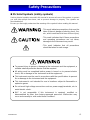
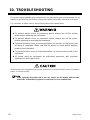
Safety Precautions
Pictorial Symbols (safety symbols)
Various pictorial symbols are used in this manual to ensure safe use of the product, to protect
you and other people from harm, and to prevent damage to property. The symbols are
described below.
Be sure you thoroughly understand the meaning of the symbols before reading this manual.
:
This mark indicates precautions that must be
taken if there is danger of electric shock, fire,
etc., which could result in loss of life or injury.
:
This mark indicates that if these precautions
and operating procedures are not taken,
damage to the instrument may result.
: This mark indicates that all precautions
should be taken for safe usage.
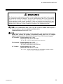
To prevent injury to persons, damage to the instrument and the equipment, a
suitable external protection device shall be required.
All wiring must be completed before power is turned on to prevent electric
shock, fire or damage to the instrument and the equipment.
This instrument must be used in accordance with the specifications to prevent
fire or damage to the instrument and the equipment.
This instrument is not intended for use in locations subject to flammable or
explosive gases.
Do not touch high-voltage connections such as power supply terminals, etc. to
avoid electric shock.
RKC is not responsible if this instrument is repaired, modified or
disassembled by other than factory-approved personnel. Malfunction may
occur and warranty is void under these conditions.

IMR02E23-E1
i-2
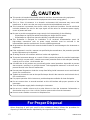
● This product is intended for use with industrial machines, test and measuring equipment.
(It is not designed for use with medical equipment and nuclear energy plant.)
● This is a Class A instrument. In a domestic environment, this instrument may cause radio
interference, in which case the user may be required to take additional measures.
● This instrument is protected from electric shock by reinforced insulation. Provide reinforced
insulation between the wire for the input signal and the wires for instrument power supply,
source of power and loads.
● Be sure to provide an appropriate surge control circuit respectively for the following:
- If input/output or signal lines within the building are longer than 30 meters.
- If input/output or signal lines leave the building, regardless the length.
● This instrument is designed for installation in an enclosed instrumentation panel. All
high-voltage connections such as power supply terminals must be enclosed in the
instrumentation panel to avoid electric shock to operating personnel.
● All precautions described in this manual should be taken to avoid damage to the instrument or
equipment.
● If the equipment is used in a manner not specified by the manufacturer, the protection provided
by the equipment may be impaired.
● All wiring must be in accordance with local codes and regulations.
● To prevent instrument damage as a result of failure, protect the power line and the input/output
lines from high currents with a suitable overcurrent protection device with adequate breaking
capacity such as a fuse, circuit breaker, etc.
● A malfunction in this product may occasionally make control operations impossible or prevent
alarm outputs, resulting in a possible hazard. Take appropriate measures in the end use to
prevent hazards in the event of malfunction.
● Prevent metal fragments or lead wire scraps from falling inside instrument case to avoid electric
shock, fire or malfunction.
● Tighten each terminal screw to the specified torque found in the manual to avoid electric shock,
fire or malfunction.
● For proper operation of this instrument, provide adequate ventilation for heat dissipation.
● Do not connect wires to unused terminals as this will interfere with proper operation of the
instrument.
● Turn off the power supply before cleaning the instrument.
● Do not use a volatile solvent such as paint thinner to clean the instrument. Deformation or
discoloration may occur. Use a soft, dry cloth to remove stains from the instrument.
● Do not connect modular connectors to telephone line.
When disposing of each part used for this instrument, always follows the procedure for
disposing of industrial wastes stipulated by the respective local community.
For Proper Disposal

IMR02E23-E1
i-3
Symbols
Pictorial Symbols (safety symbols)
: This mark indicates important information on installation, handling
and operating procedures.
: This mark indicates supplemental information on installation,
handling and operating procedures.
: This mark indicates where additional information may be located.
Abbreviation symbols
These abbreviations are used in this manual:
Abbreviation
symbols
Name
Abbreviation
symbols
Name
PV Measured value TC (input) Thermocouple (input)
SV Set value RTD (input) Resistance temperature detector (input)
MV Manipulated output value V (input) Voltage (input)
AT Autotuning I (input) Current (input)
ST Startup tuning HBA Heater break alarm
OUT Output CT Current transformer
DI Digital input LBA Control loop break alarm
DO Digital output LBD LBA deadband

IMR02E23-E1
i-4
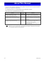
About This Manual
There are three manuals pertaining to this product. Please be sure to read all manuals
specific to your application requirements.
The following manuals can be downloaded from the official RKC website:
https://www.rkcinst.co.jp/english/download-center/
Manual
Manual
Number
Remarks
EtherCAT Communication Converter
COM-ME [For SRZ] Installation Manual
IMR02E21-E This manual is enclosed with instrument.
This manual explains the mounting and wiring.
EtherCAT Communication Converter
COM-ME [For SRZ] Communication Data List
IMR02E22-E This manual is enclosed with instrument.
This list is a compilation of the communication
data items.
EtherCAT Communication Converter
COM-ME [For SRZ] Instruction Manual
IMR02E23-E1
This manual you are reading now.
This manual describes mounting, wiring,
communication setting, protocol,
communication data, troubleshooting and
product specification.
Read this manual carefully before operating the instrument. Please place the manual
in a convenient location for easy reference.

IMR02E23-E1
i-5
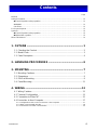
Contents
Page
NOTICE
Safety Precautions ............................................................................................................................... i-1
Pictorial Symbols (safety symbols) .............................................................................................. i-1
WARNING ....................................................................................................................................... i-1
CAUTION ........................................................................................................................................ i-2
For Proper Disposal .............................................................................................................................. i-2
Symbols ................................................................................................................................................ i-3
Pictorial Symbols (safety symbols) .............................................................................................. i-3
Abbreviation symbols ................................................................................................................... i-3
About This Manual ................................................................................................................................ i-4
1. OUTLINE .............................................................................. 1
1.1 Checking the Product ..................................................................................... 2
1.2 Model Code .................................................................................................... 3
1.3 Parts Description ............................................................................................ 4
2. HANDLING PROCEDURES ................................................ 6
3. MOUNTING .......................................................................... 7
3.1 Mounting Cautions .......................................................................................... 7
3.2 Dimensions ..................................................................................................... 9
3.3 DIN Rail Mounting .......................................................................................... 9
3.4 Panel Mounting ............................................................................................. 11
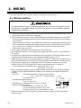
4. WIRING .............................................................................. 12
4.1 Wiring Cautions ............................................................................................ 12
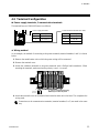
4.2 Terminal Configuration ................................................................................. 13
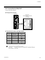
4.3 Connection to EtherCAT ............................................................................... 15
4.4 Connection to Host Computer ....................................................................... 17
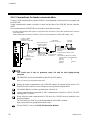
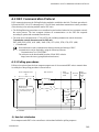
4.4.1 Configurations that can be connected to a host computer ...................................................... 17
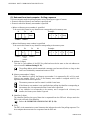
4.4.2 When connected with RS-485 ................................................................................................. 18
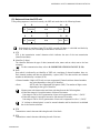
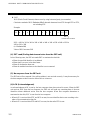
4.4.3 Connections for loader communication ................................................................................... 20

IMR02E23-E1
i-6
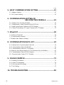
Page
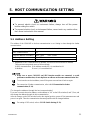
5. HOST COMMUNICATION SETTING ................................. 21
5.1 Address Setting ............................................................................................ 21
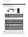
5.2 DIP Switch Setting ........................................................................................ 22
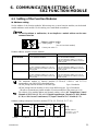
6. COMMUNICATION SETTING OF
SRZ FUNCTION MODULE ................ 23
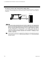
6.1 Setting of the Function Modules ................................................................... 23
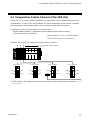
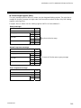
6.2 Temperature Control Channel of the SRZ Unit ............................................. 25
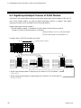
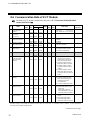
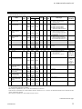
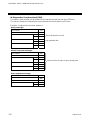
6.3 Digital Input/Output Channel of Z-DIO Module ............................................. 26
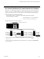
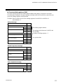
6.4 Current Transformer (CT) Input Channel of Z-CT Module ............................. 27
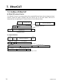
7. EtherCAT ........................................................................... 28
7.1 Outline of EtherCAT ...................................................................................... 28
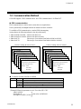
7.2 Communication Method ................................................................................. 31
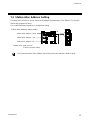
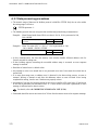
7.3 Station Alias Address Setting ........................................................................ 33
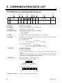
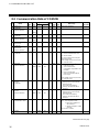
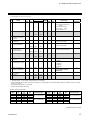
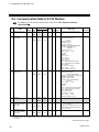
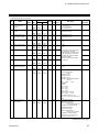
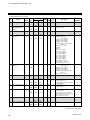
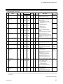
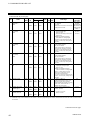
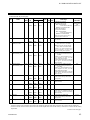
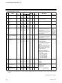
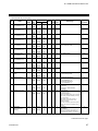
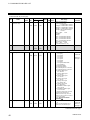
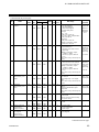
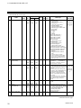
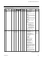
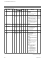
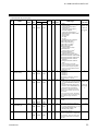
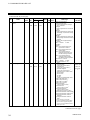
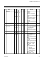
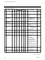
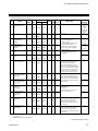
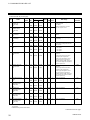
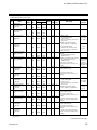
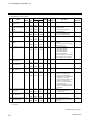
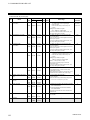
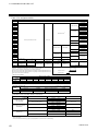
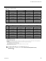
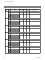
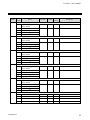
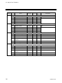
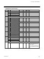
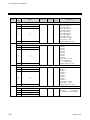
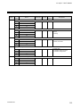
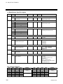
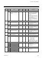
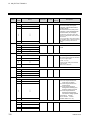
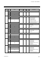
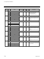
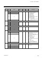
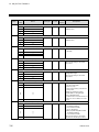
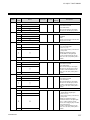
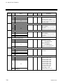
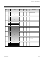
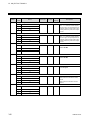
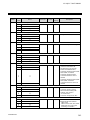
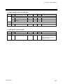
8. COMMUNICATION DATA LIST ......................................... 34
8.1 Reference to Communication Data List ........................................................ 34
8.2 Communication Data of COM-ME ................................................................ 36
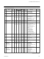
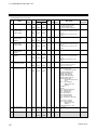
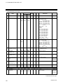
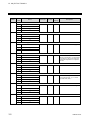
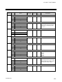
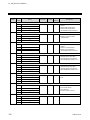
8.3 Communication Data of Z-TIO Module ......................................................... 40
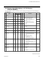
8.4 Memory Area Data Address of Z-TIO Module (only for Modbus) .................. 63
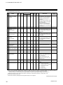
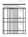
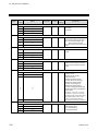
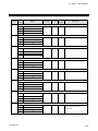
8.5 Communication Data of Z-DIO Module ......................................................... 65
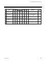
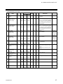
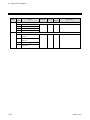
8.6 Communication Data of Z-CT Module .......................................................... 70
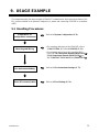
9. USAGE EXAMPLE ............................................................. 73
9.1 Handling Procedures .................................................................................... 73
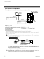
9.2 System Configuration ................................................................................... 74
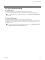
9.3 Use Instruments Settings .............................................................................. 75
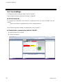
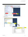
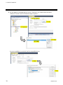
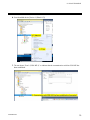
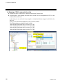
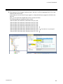
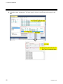
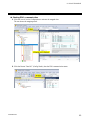
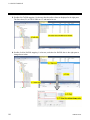
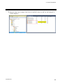
9.4 Tool Settings ................................................................................................. 76
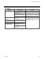
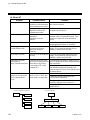
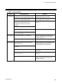
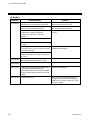
10. TROUBLESHOOTING ...................................................... 86

IMR02E23-E1
i-7
Page
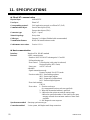
11. SPECIFICATIONS ............................................................ 91
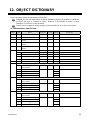
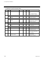
12. OBJECT DICTIONARY .................................................... 95
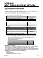
APPENDIX. HOST COMMUNICATION PROTOCOL .......... 147
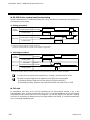
A.1 Communication Requirements .................................................................... 147
A.2 RKC Communication Protocol .................................................................... 149
A.2.1 Polling procedures ............................................................................................................... 149
A.2.2 Selecting procedures ........................................................................................................... 155
A.2.3 Communication data structure ............................................................................................. 160
A.3 Modbus Protocol ......................................................................................... 162
A.3.1 Message format ................................................................................................................... 162
A.3.2 Function code ...................................................................................................................... 163
A.3.3 Communication mode .......................................................................................................... 163
A.3.4 Slave responses .................................................................................................................. 164
A.3.5 Calculating CRC-16 ............................................................................................................. 165
A.3.6 Register read and write ....................................................................................................... 168
A.3.7 Data processing precautions ............................................................................................... 172
A.3.8 How to use memory area data ............................................................................................ 173

IMR02E23-E1
i-8
MEMO

IMR02E23-E1 1
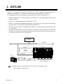
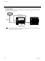
1. OUTLINE
EtherCAT communication converter COM-ME [For SRZ] (hereafter called COM-ME) is
communication converter to connect the RKC module type controller SRZ to the EtherCAT.
This chapter describes features, package contents, model code, system configuration, etc.
EtherCAT (Ethernet for Control Automation Technology) is an ultra high-speed fieldbus system
based on Ethernet.
Protocol: CAN application protocol over EtherCAT (CoE)
EtherCAT communication methods supported by the COM-ME are “PDO (process data objects)
communication” and “SDO (service data objects) communication.”
The master/slave architecture is implemented for EtherCAT communication and COM-ME is used
as a slave device.
Up to 30 function modules (Z-TIO, Z-DIO and Z-CT modules) can be connected to one COM-ME
with SRZ unit. However, the maximum joinable number of function modules of the same type is 16.
(Connectable module: Z-TIO, Z-DIO and Z-CT)
For EtherCAT, refer to the website of ETG (EtherCAT Technology Group).
URL: https://www.ethercat.org/
SRZ unit
Host
computer
Z-TIO, Z-DIO, and Z-CT modules
(Up to 30 modules)
RKC communication
Modbus
RS-485
Host
communication
Master
instrument
EtherCAT
EtherCAT
Communication Converter
COM-ME
[Slave]
EtherCAT

1. OUTLINE
IMR02E23-E1
2
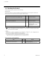
1.1 Checking the Product
Before using this product, check each of the following:
Model code
Check that there are no scratch or breakage in external appearance (case, front panel, or terminal, etc.)
Check that all of the items delivered are complete. (Refer to below)
Name Q’TY Remarks
COM-ME [For SRZ] Installation Manual (IMR02E21-E) 1 Enclosed with instrument
COM-ME [For SRZ] Communication Data List (IMR02E22-E) 1 Enclosed with instrument
Joint connector cover KSRZ-517A 2 Enclosed with instrument
Power terminal cover KSRZ-518A 1 Enclosed with instrument
COM-ME [For SRZ] Instruction Manual (IMR02E23-E1) 1 This manual (sold separately)
This manual can be downloaded from the
official RKC website:
https://www.rkcinst.co.jp/english/
download-center/
ESI file * 1
D
ownload
If any of the products are missing, damaged, or if your manual is incomplete, please contact
RKC sales office or the agent.
* ESI file
The ESI file is used for recognition of the COM-ME on EtherCAT in the configuration tool
(software for environment settings and creating programs).
If you require the ESI file, download it from the official RKC website.
https://www.rkcinst.co.jp/english/field_network_category/ethercat/
Accessories (sold separately)
Name Q’TY Remarks
End plate DEP-01 2 Secures the SRZ on the DIN rail
Communication converter COM-K2-1 1
For loader communication
(Option: with loader communication cable)

1. OUTLINE
IMR02E23-E1
3
1.2 Model Code
Check whether the delivered product is as specified by referring to the following model code list.
If the product is not identical to the specifications, please contact RKC sales office or the agent.
(1) Ethernet communication type
3: EtherCAT
(2) Host communication interface (COM. PORT)
5: RS-485
(3) Corresponding to the RKC controller
02: SRZ
COM- ME - 3 5 02
(1) (2) (3)

1. OUTLINE
IMR02E23-E1
4
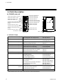
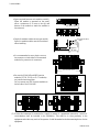
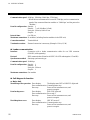
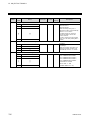
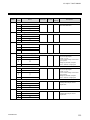
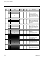
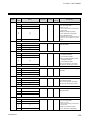
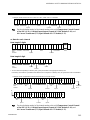
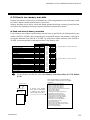
1.3 Parts Description
COM-ME main unit
Indication lamps
BRD FLT [Red] While in normal state: Turns off
Self-diagnostic error (Major fault): Red lamp turns on
RX/TX [Green] During host communication data send and receive:
Green lamp turns on
HRTBT [Green] While software is properly running: Green lamp turns on
WDT
(watchdog timer)
error: Turns off
24V [Green] While 24V power is supplied: Green lamp turns on
FW OP MD [Green] While OP is functioning: Green lamp turns on
While Safe-OP is functioning: Green lamp blinks
FW DWNLD [Green] When the firmware is successfully started: Green lamp turns on
When the firmware fails to be started: Turns off
When the firmware is re-written: Turns off
DRVR FLT This lamp is not used.
RUN [Green] INIT or No power: Turns off
OPERATIONAL: Green lamp turns on
PRE-OPERATIONAL: Green lamp blinks
SAFE-OPERATIONAL: Green lamp single-flashes *
ERR [Red] No error or No power: Turns off
Configuration error: Red lamp blinks
Local error: Red lamp single-flashes *
Communication refused by the Master: Red lamp double-flashes *
Co WDTO inside the Slave: Red lamp turns on
Starting error: Red lamp flashes fast
Link/Activity (Port 1/Port 2)
[Green]
No link or No power: Turns off
Link sensed, activity detected: Green lamp flashes fast
Link sensed, no activity: Green lamp turns on
OPT (Port1/Port2) [Yellow] Constantly off
* Single flashing: Repeats ON (200 ms)/OFF (100 ms).
Double flashing: Repeats ON (200 ms)/OFF (200 ms)/ON (200 ms)/OFF (1000 ms).
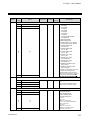
Loader communication connecto
r
Station Alias Address (100)
Indication lamp ERR
Indication lamp RUN
Station Alias Address (10)
Station Alias Address (1)
Indication lamp Link/Activity (Port 1)
EtherCAT
connecto
r
[ECAT OUT]
(Port 1)
Indication lamp OPT (Port 1)
Indication lamp Link/Activity (Port 2)
EtherCAT connecto
r
[ECAT IN]
(Port 2)
Indication lamp OPT (Port 2)
FG terminal
Indication lamp RX/TX
Indication lamp BRD FLT
Indication lamp HRTBT
Indication lamp 24V
Indication lamp FW OP MD
Indication lamp FW DWNLD
Indication lamp DRVR FLT
Indication lamp 3.4V
Indication lamp 1.0V
Left side view
DIP switch
Base
Front view

1. OUTLINE
IMR02E23-E1
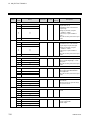
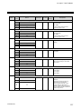
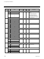
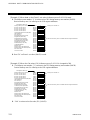
5
Communication port (modular connector) and communication connector
Loader communication
connector
Use to connecting the communication converter and personal computer
when loader communication is performed.
EtherCAT connector (Port 1)
[ECAT OUT]
Designed to connect EtherCAT with the next slave instrument.
EtherCAT connector (Port 2)
[ECAT IN]
Designed to connect EtherCAT with the master instrument or the slave
instrument located near the master instrument.
Switch
Station Alias Address setting
switch (100, 10, 1)
Used to set Station Alias Address (Hexadecimal) of EtherCAT.
DIP switch Sets communication speed and communication protocol
corresponding to host communication.
Sets DIP switch setting validity/invalidity.
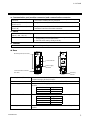
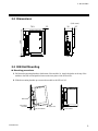
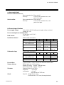
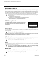
Terminal
FG terminal Terminal for grounding
Base
Mounting holes (M3 screw) Holes for screws to fix the base to a panel, etc.
Customer must provide the M3 screws.
Joint connector Used to mechanically and electrically connect each module.
Power supply terminals These are terminals to supply power to the COM-ME and joined function
modules.
Terminal number Signal name
1 24 V DC (+)
2
24 V DC ()
Terminal 3, 4 and 5 These terminals connection to a host computer or an operation panel (HMI).
Terminal number Signal name
3 T/R (A)
4 T/R (B)
5 SG
Mounting bracket
Used to fix the module on DIN rails and also to fix each module joined
together.
Mounting holes (M3 screw)
Power supply
terminals
Joint connector
Mounting
bracket
Communication terminals
(RS-485)
Front Rea
r

6 IMR02E23-E1
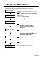
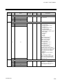
2. HANDLING PROCEDURES
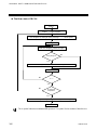
Conduct necessary setting before operation according to the procedure described below.
Mounting
Install the COM-ME.
Refer to 3. MOUNTING (P. 7).
For controller (SRZ), refer to Z-TIO Instruction Manual
(IMS01T01-E), Z-DIO Instruction Manual
(IMS01T03-E), and Z-CT Instruction Manual
(IMS01T16-E).
Host communication
settings
Wiring
Controller (SRZ) settings
The address, communication speed, communication protocol, data bi
t
configuration, and DIP switch setting validate/invalidate of hos
t
communication are set only when host communication is used in the
COM-ME.
Refer to 5. HOST COMMUNICATION SETTINGS (P. 21).
Connect the COM-ME
p
ower wiring and the controller (SRZ) wiring,
and connect the COM-ME to the EherCAT master. Connect the wiring
for host communication or loader communication in the COM-ME.
Refer to 4. WIRING (P. 12)
For controller (SRZ), refer to Z-TIO Instruction Manual
(IMS01T01-E), Z-DIO Instruction Manual
(IMS01T03-E), and Z-CT Instruction Manual
(IMS01T16-E).
Set the communication setting of controller (SRZ).
Refer to 6. COMMUNICATIOM SETTING OF SRZ
FUNCTION MODULE (P. 23).
For controller (SRZ), refer to Z-TIO Host Communication
Quick Instruction Manual (IMS01T02-E),
Z-DIO Instruction Manual (IMS01T03-E), and Z-CT
Instruction Manual (IMS01T16-E).
EtherCAT
communication settings
Configure initial settings for EtherCAT communication.
Refer to 7.2 EtherCAT Communication Setting (P. 31).
Refer to 9.4 Tool Settings (P. 76).
Other communication
data settings
Set the data for the COM-ME and controller (SRZ).
Refer to 8. COMMUNICATION DATA LIST (P.34).
EtherCAT
communication
Execute PDO communication or SDO communication.

IMR02E23-E1 7
3. MOUNTING
This chapter describes installation environment, mounting cautions, dimensions and mounting procedures.
3.1 Mounting Cautions
(1) This instrument is intended to be used under the following environmental conditions.
(IEC 61010-1) [POLLUTION DEGREE 2]
(2) Use this instrument within the following environment conditions:
Allowable ambient temperature: 10 to 55 C
Allowable ambient humidity: 5 to 95 %RH
(Absolute humidity: MAX. W. C 29 g/m
3
dry air at 101.3 kPa)
Installation environment conditions: Indoor use
Altitude up to 2000 m
(3) Avoid the following conditions when selecting the mounting location:
Rapid changes in ambient temperature which may cause condensation.
Corrosive or inflammable gases.
Direct vibration or shock to the main unit.
Water, oil, chemicals, vapor or steam splashes.
Excessive dust, salt or iron particles.
Excessive induction noise, static electricity, magnetic fields or noise.
Direct air flow from an air conditioner.
Exposure to direct sunlight.
Excessive heat accumulation.
(4) Mount this instrument in the panel considering the following conditions:
Provide adequate ventilation space so that heat does not build up.
Do not mount this instrument directly above the equipment that generates large amount of heat
(heaters, transformers, semi-conductor functional devices, large-wattage resistors.)
If the ambient temperature rises above 55 C, cool this instrument with a forced air fan, cooler, or
the like. Cooled air should not blow directly on this instrument.
In order to improve safety and the immunity to withstand noise, mount this instrument as far away
as possible from high voltage equipment, power lines, and rotating machinery.
High voltage equipment: Do not mount within the same panel.
Power lines: Separate at least 200 mm
Rotating machinery: Separate as far as possible
For correct functioning mount this instrument in a horizontal position.
To prevent electric shock or instrument failure, always turn off the power before
mounting or removing the instrument.

3. MOUNTING
IMR02E23-E1
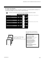
8
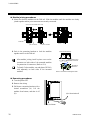
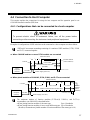
Space required between each module vertically
When the module is mounted on the panel,
allow a minimum of 50 mm at the top and
bottom of the module to attach the module to
the main unit.
Depth for modular cables mount type module
Space for modular cables must be considered
when installing.
It is recommended to use a plastic cover on
the connector on both sides of the mounted
modules for protection of connectors.
Be sure the COM-ME and SRZ function
modules (Z-TIO, Z-DIO, or Z-CT modules)
are joined when using them.
Do not connect any SRZ function modules to
the left side of the COM-ME.
(5) In case this instrument is connected to a supply by means of a permanent connection, a switch or
circuit-breaker shall be included in the installation. This shall be in close proximity to the
equipment and within easy reach of the operator. It shall be marked as the disconnecting device for the
equipment.
76.9 mm
Approx.
50 mm
Communication
cable
Joint connector cover
50 mm or more
COM-ME

3. MOUNTING
IMR02E23-E1
9
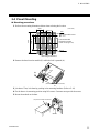
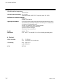
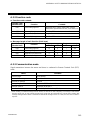
3.2 Dimensions
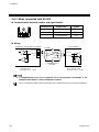
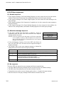
3.3 DIN Rail Mounting
Mounting procedures
1. Pull down the mounting bracket at the bottom of the module (A). Attach the hooks on the top of the
module to the DIN rail and push the lower section into place on the DIN rail (B).
2. Slide the mounting bracket up to secure the module to the DIN rail (C).
(B) Push
Mounting
bracket
DIN rail
(A) Pull down
(C) Locked
76.9
30 6.7
100
5
2.5
(Unit: mm)

3. MOUNTING
IMR02E23-E1
10
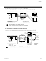
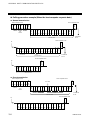
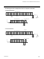
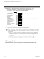
Module joining procedures
1. Mount the function modules on the DIN rail. Slide the modules until the modules are closely
joined together and the joint connectors are securely connected.
2. Push in the mounting brackets to lock the modules
together and fix to the DIN rail.
After module joining, install a
plastic cover on the
connector on both sides of the mounted modules
for protection of connectors. (Refer to P. 8)
To firmly fix the modules, use end plates (DEP-01)
sold separately on both sides of the mounted
modules.
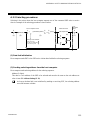
Removing procedures
1. Turn the power OFF.
2. Remove the wiring.
3. Pull down a mounting bracket with a
slotted screwdriver (A). Lift the
module from bottom, and take it off
(B).
(Front view of module main unit)
Joint connector
Function module
COM-ME
(Rear view of base)
Push in all of the mounting brackets.
Mounting
bracket
State where each
module is locked.
(A) Pull down
(B) Lift and take off
La pagina si sta caricando...
La pagina si sta caricando...
La pagina si sta caricando...
La pagina si sta caricando...
La pagina si sta caricando...
La pagina si sta caricando...
La pagina si sta caricando...
La pagina si sta caricando...
La pagina si sta caricando...
La pagina si sta caricando...
La pagina si sta caricando...
La pagina si sta caricando...
La pagina si sta caricando...
La pagina si sta caricando...
La pagina si sta caricando...
La pagina si sta caricando...
La pagina si sta caricando...
La pagina si sta caricando...
La pagina si sta caricando...
La pagina si sta caricando...
La pagina si sta caricando...
La pagina si sta caricando...
La pagina si sta caricando...
La pagina si sta caricando...
La pagina si sta caricando...
La pagina si sta caricando...
La pagina si sta caricando...
La pagina si sta caricando...
La pagina si sta caricando...
La pagina si sta caricando...
La pagina si sta caricando...
La pagina si sta caricando...
La pagina si sta caricando...
La pagina si sta caricando...
La pagina si sta caricando...
La pagina si sta caricando...
La pagina si sta caricando...
La pagina si sta caricando...
La pagina si sta caricando...
La pagina si sta caricando...
La pagina si sta caricando...
La pagina si sta caricando...
La pagina si sta caricando...
La pagina si sta caricando...
La pagina si sta caricando...
La pagina si sta caricando...
La pagina si sta caricando...
La pagina si sta caricando...
La pagina si sta caricando...
La pagina si sta caricando...
La pagina si sta caricando...
La pagina si sta caricando...
La pagina si sta caricando...
La pagina si sta caricando...
La pagina si sta caricando...
La pagina si sta caricando...
La pagina si sta caricando...
La pagina si sta caricando...
La pagina si sta caricando...
La pagina si sta caricando...
La pagina si sta caricando...
La pagina si sta caricando...
La pagina si sta caricando...
La pagina si sta caricando...
La pagina si sta caricando...
La pagina si sta caricando...
La pagina si sta caricando...
La pagina si sta caricando...
La pagina si sta caricando...
La pagina si sta caricando...
La pagina si sta caricando...
La pagina si sta caricando...
La pagina si sta caricando...
La pagina si sta caricando...
La pagina si sta caricando...
La pagina si sta caricando...
La pagina si sta caricando...
La pagina si sta caricando...
La pagina si sta caricando...
La pagina si sta caricando...
La pagina si sta caricando...
La pagina si sta caricando...
La pagina si sta caricando...
La pagina si sta caricando...
La pagina si sta caricando...
La pagina si sta caricando...
La pagina si sta caricando...
La pagina si sta caricando...
La pagina si sta caricando...
La pagina si sta caricando...
La pagina si sta caricando...
La pagina si sta caricando...
La pagina si sta caricando...
La pagina si sta caricando...
La pagina si sta caricando...
La pagina si sta caricando...
La pagina si sta caricando...
La pagina si sta caricando...
La pagina si sta caricando...
La pagina si sta caricando...
La pagina si sta caricando...
La pagina si sta caricando...
La pagina si sta caricando...
La pagina si sta caricando...
La pagina si sta caricando...
La pagina si sta caricando...
La pagina si sta caricando...
La pagina si sta caricando...
La pagina si sta caricando...
La pagina si sta caricando...
La pagina si sta caricando...
La pagina si sta caricando...
La pagina si sta caricando...
La pagina si sta caricando...
La pagina si sta caricando...
La pagina si sta caricando...
La pagina si sta caricando...
La pagina si sta caricando...
La pagina si sta caricando...
La pagina si sta caricando...
La pagina si sta caricando...
La pagina si sta caricando...
La pagina si sta caricando...
La pagina si sta caricando...
La pagina si sta caricando...
La pagina si sta caricando...
La pagina si sta caricando...
La pagina si sta caricando...
La pagina si sta caricando...
La pagina si sta caricando...
La pagina si sta caricando...
La pagina si sta caricando...
La pagina si sta caricando...
La pagina si sta caricando...
La pagina si sta caricando...
La pagina si sta caricando...
La pagina si sta caricando...
La pagina si sta caricando...
La pagina si sta caricando...
La pagina si sta caricando...
La pagina si sta caricando...
La pagina si sta caricando...
La pagina si sta caricando...
La pagina si sta caricando...
La pagina si sta caricando...
La pagina si sta caricando...
La pagina si sta caricando...
La pagina si sta caricando...
La pagina si sta caricando...
La pagina si sta caricando...
La pagina si sta caricando...
La pagina si sta caricando...
La pagina si sta caricando...
La pagina si sta caricando...
La pagina si sta caricando...
La pagina si sta caricando...
La pagina si sta caricando...
La pagina si sta caricando...
La pagina si sta caricando...
La pagina si sta caricando...
La pagina si sta caricando...
La pagina si sta caricando...
La pagina si sta caricando...
La pagina si sta caricando...
La pagina si sta caricando...
La pagina si sta caricando...
La pagina si sta caricando...
La pagina si sta caricando...
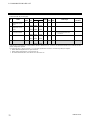
-
 1
1
-
 2
2
-
 3
3
-
 4
4
-
 5
5
-
 6
6
-
 7
7
-
 8
8
-
 9
9
-
 10
10
-
 11
11
-
 12
12
-
 13
13
-
 14
14
-
 15
15
-
 16
16
-
 17
17
-
 18
18
-
 19
19
-
 20
20
-
 21
21
-
 22
22
-
 23
23
-
 24
24
-
 25
25
-
 26
26
-
 27
27
-
 28
28
-
 29
29
-
 30
30
-
 31
31
-
 32
32
-
 33
33
-
 34
34
-
 35
35
-
 36
36
-
 37
37
-
 38
38
-
 39
39
-
 40
40
-
 41
41
-
 42
42
-
 43
43
-
 44
44
-
 45
45
-
 46
46
-
 47
47
-
 48
48
-
 49
49
-
 50
50
-
 51
51
-
 52
52
-
 53
53
-
 54
54
-
 55
55
-
 56
56
-
 57
57
-
 58
58
-
 59
59
-
 60
60
-
 61
61
-
 62
62
-
 63
63
-
 64
64
-
 65
65
-
 66
66
-
 67
67
-
 68
68
-
 69
69
-
 70
70
-
 71
71
-
 72
72
-
 73
73
-
 74
74
-
 75
75
-
 76
76
-
 77
77
-
 78
78
-
 79
79
-
 80
80
-
 81
81
-
 82
82
-
 83
83
-
 84
84
-
 85
85
-
 86
86
-
 87
87
-
 88
88
-
 89
89
-
 90
90
-
 91
91
-
 92
92
-
 93
93
-
 94
94
-
 95
95
-
 96
96
-
 97
97
-
 98
98
-
 99
99
-
 100
100
-
 101
101
-
 102
102
-
 103
103
-
 104
104
-
 105
105
-
 106
106
-
 107
107
-
 108
108
-
 109
109
-
 110
110
-
 111
111
-
 112
112
-
 113
113
-
 114
114
-
 115
115
-
 116
116
-
 117
117
-
 118
118
-
 119
119
-
 120
120
-
 121
121
-
 122
122
-
 123
123
-
 124
124
-
 125
125
-
 126
126
-
 127
127
-
 128
128
-
 129
129
-
 130
130
-
 131
131
-
 132
132
-
 133
133
-
 134
134
-
 135
135
-
 136
136
-
 137
137
-
 138
138
-
 139
139
-
 140
140
-
 141
141
-
 142
142
-
 143
143
-
 144
144
-
 145
145
-
 146
146
-
 147
147
-
 148
148
-
 149
149
-
 150
150
-
 151
151
-
 152
152
-
 153
153
-
 154
154
-
 155
155
-
 156
156
-
 157
157
-
 158
158
-
 159
159
-
 160
160
-
 161
161
-
 162
162
-
 163
163
-
 164
164
-
 165
165
-
 166
166
-
 167
167
-
 168
168
-
 169
169
-
 170
170
-
 171
171
-
 172
172
-
 173
173
-
 174
174
-
 175
175
-
 176
176
-
 177
177
-
 178
178
-
 179
179
-
 180
180
-
 181
181
-
 182
182
-
 183
183
-
 184
184
-
 185
185
-
 186
186
-
 187
187
-
 188
188


in altre lingue
- English: RKC INSTRUMENT COM-ME-3 User manual
Documenti correlati
-
RKC INSTRUMENT COM-ME-1 Manuale utente
-
-
-
-
-
-
-
-
-
Altri documenti
-
DAB MCE-C Istruzioni per l'uso
-
Shinko VCD-100 Manuale utente
-
LD Systems IPA 412 T Manuale del proprietario
-
Spectrum Controls 1794sc-IF8IU Guida utente
-
Leuze BPS 338i SM 100 H Istruzioni per l'uso
-
-
WAGO ETHERNET Controller /XTR Manuale utente
-
Danfoss 080G3296 Guida d'installazione
-
-