RKC INSTRUMENT COM-MY Communication Data List
- Tipo
- Communication Data List

NOV. 2007 IMR02E04-E1
IMR02E04-E1 1
SRZ Communication Data List
[Z-TIO/Z-DIO/Z-CT modules]
MECHATROLINK Communication Converter
C
O
M
-
MY
Thank you for purchasing this RKC product. In order to achieve maximum performance and ensure proper
operation of your new instrument, carefully read all the instructions in this manual. Please place this
manual in a convenient location for easy reference.
This manual shows SRZ data which can be used for communication between the PLC/host computer and
COM-MY. For the installation and various function settings, please read if necessary the following separate
manuals.
• COM-MY Installation Manual (IMR02E01-E) Enclosed with COM-MY
• COM-MY Instruction Manual (IMR02E02-E) Enclosed with COM-MY
• COM-MY Communication Data List (IMR02E03-E) Enclosed with COM-MY
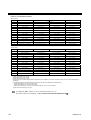
1. Reference to Communication Data List
Register address
No.
Name
Iden-
tifier
Chan-
nel
HEX DEC
Digits
Attri-
bute
Struc-
ture
Data range
Factory
set value
1 Measured value (PV) M1 CH1
·
·
·
CH64
01FC
·
·
·
023B
508
·
·
·
571
7 RO C Input scale low to Input scale high
(1)
(2) (4) (5) (6) (8) (9) (3) (7)
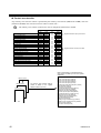
(1) Name: Communication data name
(2) Identifier: Communication identifier of RKC communication
(3) Channel: Channel number of data of one unit
(4) Register address: Register address of Modbus and MECHATROLINK data item specification
(HEX: Hexadecimal DEC: Decimal)
(5) Digits: The number of communication data digits in RKC communication
(6) Attribute: A method of how communication data items are read or written when viewed from
the host computer or PLC is described
RO: Read only data
R/W:
Read and Write data
(7) Structure: C: Data for each channel
1, 2
M: Data for each module
U: Data for each SRZ unit
1
On a Z-TIO module (2-channel type), the communication data of the CH3 and CH4
becomes invalid.
2
Parameters only used for heat/cool control or position proportioning control, therefore data
(indicated by ♣ in the name column) for CH2 and CH4 of Z-TIO modules are unused.
[Read is possible (0 is shown), but the result of Write is disregarded.]
Continued on the next page.
Host computer or PLC
Data direction
SRZ
Host computer or PLC
Data direction
SRZ

IMR02E04-E1
2
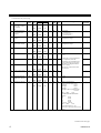
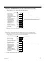
(8) Data range: Read or write range of communication data
• ASCII code data (Example: 7 digits)
• 16-bit data (bit image)
(9) Factory set value: Factory set value of communication data
Communication includes both “Normal setting data” and “Engineering setting data.”
During RUN (control), the attribute of engineering setting data is RO. To configure
engineering setting data, the RUN/STOP switch must be set to STOP (control stopped).
Z-TIO module: Normal setting data No. 1 to 85,
Engineering setting data No. 86 to 208
Z-DIO module: Normal setting data No. 1 to 13,
Engineering setting data No. 14 to 27
Z-CT module: Normal setting data No. 1 to 28 *
* No. 17 to 28: When the set lock (Identifier:LK, Resister address: 5E0CH to
5E1BH) is set to “0: Unlock,” writing data is possible.
The Engineering setting data should be set according to the application before setting any
parameter related to operation. Once the Engineering setting data are set correctly, those
datas are not necessary to be changed for the same application under normal conditions. If
they are changed unnecessarily, it may result in malfunction or failure of the instrument. RKC
will not bear any responsibility for malfunction or failure as a result of improper changes in
the Engineering setting.
Data mapping function
When using a COM-MY joined to function modules (Z-TIO, Z-DIO, Z-CT modules of SRZ), the
data mapping function cannot be used.
Most
significant digit
Least
significant digit
…………
b15
b0
…………….……………………

IMR02E04-E1
3
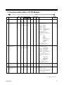
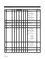
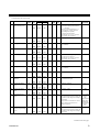
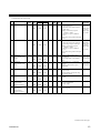
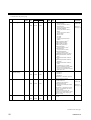
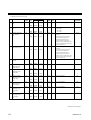
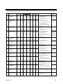
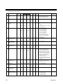
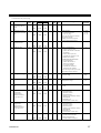
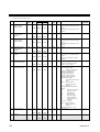
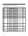
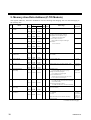
2. Communication Data of Z-TIO Module
For details of Z-TIO module communication data, see SRZ Instruction Manual (IMS01T04-E).
Register address
No. Name
Iden-
tifier
Chan-
nel
HEX DEC
Digits
Attri-
bute
Struc-
ture
Data range
Factory
set value
1 Measured value (PV) M1 CH1
·
·
·
CH64
01FC
·
·
·
023B
508
·
·
·
571
7 RO C Input scale low to Input scale high
2 Comprehensive
event state
AJ CH1
·
·
·
CH64
023C
·
·
·
027B
572
·
·
·
635
7 RO C • RKC communication
Least significant digit:
Event 1
2nd digit: Event 2
3rd digit: Event 3
4th digit: Event 4
5th digit: Heater break alarm
6th digit: Temperature rise
completion
7th digit: Burnout
Data 0: OFF 1: ON
• Modbus/MECHATROLINK
Bit data
b0: Event 1
b1: Event 2
b2: Event 3
b3: Event 4
b4: Heater break alarm
b5: Temperature rise
completion
b6: Burnout
b7 to b15: Unused
Data 0: OFF 1: ON
[Decimal number: 0 to 127]
3 Operation mode
state monitor
L0 CH1
·
·
·
CH64
027C
·
·
·
02BB
636
·
·
·
699
7 RO C • RKC communication
Least significant digit:
Control STOP
2nd digit: Control RUN
3rd digit: Manual mode
4th digit: Remote mode
5th digit to Most significant digit:
Unused
Data 0: OFF 1: ON
• Modbus/MECHATROLINK
Bit data
b0: Control STOP
b1: Control RUN
b2: Manual mode
b3: Remote mode
b4 to b15: Unused
Data 0: OFF 1: ON
[Decimal number: 0 to 15]
4 Unused 02BC
·
·
·
02CB
700
·
·
·
715
5 Manipulated output
value (MV) monitor
[heat-side]
♣
O1 CH1
·
·
·
CH64
02CC
·
·
·
030B
716
·
·
·
779
7 RO C PID control or heat/cool PID
control:
−5.0 to +105.0 %
Position proportioning control with
feedback resistance (FBR) input:
0.0 to 100.0 %
Continued on the next page.

IMR02E04-E1
4
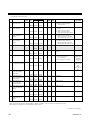
Continued from the previous page.
Register address
No. Name
Iden-
tifier
Chan-
nel
HEX DEC
Digits
Attri-
bute
Struc-
ture
Data range
Factory
set value
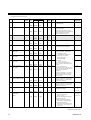
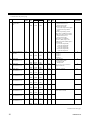
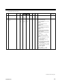
6 Manipulated output
value (MV) monitor
[cool-side]
♣
O2 CH1
·
·
·
CH64
030C
·
·
·
034B
780
·
·
·
843
7 RO C −5.0 to +105.0 %
7 Current transformer
(CT) input value
monitor
M3 CH1
·
·
·
CH64
034C
·
·
·
038B
844
·
·
·
907
7 RO C CTL-6-P-N:
0.0 to 30.0 A
CTL-12-S56-10L-N:
0.0 to 100.0 A
8 Set value (SV)
monitor
MS CH1
·
·
·
CH64
038C
·
·
·
03CB
908
·
·
·
971
7 RO C Setting limiter (low) to
Setting limiter (high)
9 Remote setting (RS)
input value monitor
S2 CH1
·
·
·
CH64
03CC
·
·
·
040B
972
·
·
·
1035
7 RO C Setting limiter (low) to
Setting limiter (high)
10 Burnout state monitor B1 CH1
·
·
·
CH64
040C
·
·
·
044B
1036
·
·
·
1099
1 RO C 0: OFF
1: ON
11 Event 1 state monitor AA CH1
·
·
·
CH64
044C
·
·
·
048B
1100
·
·
·
1163
1 RO C
12 Event 2 state monitor AB CH1
·
·
·
CH64
048C
·
·
·
04CB
1164
·
·
·
1227
1 RO C
13 Event 3 state monitor AC CH1
·
·
·
CH64
04CC
·
·
·
050B
1228
·
·
·
1291
1 RO C
14 Event 4 state monitor AD CH1
·
·
·
CH64
050C
·
·
·
054B
1292
·
·
·
1355
1 RO C
0: OFF
1: ON
If the Event 3 type is temperature
rise completion, check the
temperature rise completion state
in the comprehensive event state
(Identifier: AJ, Register address:
023C to 027B).
(The Event 3 state monitor does
not turn ON.)
15 Heater break alarm
(HBA) state monitor
AE CH1
·
·
·
CH64
054C
·
·
·
058B
1356
·
·
·
1419
1 RO C 0: OFF
1: ON
16 Output state monitor Q1 CH1
·
·
·
CH16
058C
·
·
·
059B
1420
·
·
1435
7 RO M • RKC communication
Least significant digit: OUT1
2nd digit: OUT2
3rd digit: OUT3
4th digit: OUT4
5th digit to Most significant digit:
Unused
Data 0: OFF 1: ON
• Modbus/MECHATROLINK
Bit data
b0: OUT1
b1: OUT2
b2: OUT3
b3: OUT4
b4 to b15: Unused
Data 0: OFF 1: ON
[Decimal number: 0 to 15]
Valid only for time-proportional control
output.
Continued on the next page.

IMR02E04-E1
5
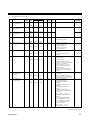
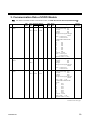
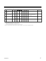
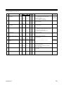
Continued from the previous page.
Register address
No. Name
Iden-
tifier
Chan-
nel
HEX DEC
Digits
Attri-
bute
Struc-
ture
Data range
Factory
set value
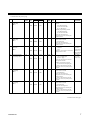
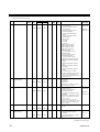
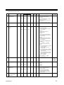
17 Memory area soak
time monitor
TR CH1
·
·
·
CH64
059C
·
·
·
05DB
1436
·
·
·
1499
7 RO C 0 minutes 00 seconds to 199 minutes
59 seconds:
RKC communication:
0:00 to 199:59 (min:sec)
Modbus/MECHATROLINK
0 to 11999 seconds
0 hours 00 minutes to 99 hours 59
minutes:
RKC communication:
0:00 to 99:59 (hrs:min)
Modbus/MECHATROLINK
0 to 5999 minutes
Data range of Area soak time can be
selected on the Soak time unit.
18 Unused 05DC
·
·
·
05EB
1500
·
·
·
1515
19 Holding peak value
ambient temperature
monitor
Hp CH1
·
·
·
CH64
05EC
·
·
·
062B
1516
·
·
·
1579
7 RO C −10.0 to +100.0 °C
(14.0 to 212.0 °F)
20 Unused 062C
·
·
·
063B
1580
·
·
·
1595
21 Logic output
monitor 1
ED CH1
·
·
·
CH16
063C
·
·
·
064B
1596
·
·
·
1611
7 RO M • RKC communication
Least significant digit:
Logic output 1
2nd digit: Logic output 2
3rd digit: Logic output 3
4th digit: Logic output 4
5th digit to Most significant digit:
Unused
Data 0: OFF 1: ON
• Modbus/MECHATROLINK
Bit data
b0: Logic output 1
b1: Logic output 2
b2: Logic output 3
b3: Logic output 4
b4: Logic output 5
b5: Logic output 6
b6: Logic output 7
b7: Logic output 8
b8 to b15: Unused
Data 0: OFF 1: ON
[Decimal number: 0 to 255]
22 Logic output
monitor 2
EE CH1
·
·
·
CH16
7 RO M Least significant digit:
Logic output 5
2nd digit: Logic output 6
3rd digit: Logic output 7
4th digit: Logic output 8
5th digit to Most significant digit:
Unused
Data 0: OFF 1: ON
23 Unused 064C
·
·
·
080B
1612
·
·
·
2059
24 PID/AT transfer G1 CH1
·
·
·
CH64
080C
·
·
·
084B
2060
·
·
·
2123
1 R/W C 0: PID control
1: Autotuning (AT)
0
Continued on the next page.

IMR02E04-E1
6
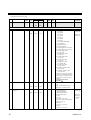
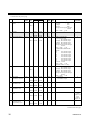
Continued from the previous page.
Register address
No. Name
Iden-
tifier
Chan-
nel
HEX DEC
Digits
Attri-
bute
Struc-
ture
Data range
Factory
set value
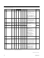
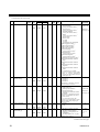
25 Auto/Manual transfer J1 CH1
·
·
·
CH64
084C
·
·
·
088B
2124
·
·
·
2187
1 R/W C 0: Auto mode
1: Manual mode
0
26 Remote/Local transfer C1 CH1
·
·
·
CH64
088C
·
·
·
08CB
2188
·
·
·
2251
1 R/W C 0: Local mode
1: Remote mode
When performing remote control by
remote setting input and also performing
cascade control and ratio setting,
transfer to the Remote mode.
0
27 Unused 08CC
·
·
·
08DB
2252
·
·
·
2267
28 Memory area transfer ZA CH1
·
·
·
CH64
08DC
·
·
·
091B
2268
·
·
·
2331
7 R/W C 1 to 8 1
29 Interlock release AR CH1
·
·
·
CH64
091C
·
·
·
095B
2332
·
·
·
2395
1 R/W C 0: Normal state
1: Interlock release execution
0
30 Event 1 set value
(EV1) ★
A1 CH1
·
·
·
CH64
095C
·
·
·
099B
2396
·
·
·
2459
7 R/W C 50
31 Event 2 set value
(EV2) ★
A2 CH1
·
·
·
CH64
099C
·
·
·
09DB
2460
·
·
·
2523
7 R/W C 50
32
Event 3 set value
(EV3) ★
A3 CH1
·
·
·
CH64
09DC
·
·
·
0A1B
2524
·
·
·
2587
7 R/W C 50
33
Event 4 set value
(EV4) ★
A4 CH1
·
·
·
CH64
0A1C
·
·
·
0A5B
2588
·
·
·
2651
7 R/W C
Deviation action, Deviation action
between channels, Temperature
rise completion range:
−Input span to +Input span
Process action, SV action:
Input scale low to
Input scale high
MV action:
−5.0 to +105.0 %
If the Event type corresponds to “0:
None,” set to RO (Only reading data is
possible).
If Event 3 corresponds to
“9: Temperature rise completion,” the
Event 3 set value becomes the range for
determining temperature rise
completion.
If Event 4 corresponds to “9: Control
loop break alarm (LBA),” the Event 4
set value becomes RO (Only reading
data is possible).
50
34 Control loop break
alarm (LBA) time ★
A5 CH1
·
·
·
CH64
0A5C
·
·
·
0A9B
2652
·
·
·
2715
7 R/W C 0 to 7200 seconds (0: Unused)
If Event 4 is other than “9: Control loop
break alarm (LBA),” set to RO (Only
reading data is possible).
480
35 LBA deadband ★ N1 CH1
·
·
·
CH64
0A9C
·
·
·
0ADB
2716
·
·
·
2779
7 R/W C 0 (0.0) to Input span
If Event 4 is other than “9: Control loop
break alarm (LBA),” set to RO (Only
reading data is possible).
0 (0.0)
36 Set value (SV) ★ S1 CH1
·
·
·
CH64
0ADC
·
·
·
0B1B
2780
·
·
·
2843
7 R/W C Setting limiter (low) to
Setting limiter (high)
TC/RTD:
0
V/I: 0.0
37 Proportional band
[heat-side]
★ ♣
P1 CH1
·
·
·
CH64
0B1C
·
·
·
0B5B
2844
·
·
·
2907
7 R/W C
TC/RTD inputs:
0 (0.0) to Input span
(Unit: °C [°F])
Varies with the setting of the decimal
point position selection.
Voltage (V)/current (I) inputs:
0.0 to 1000.0 % of input span
0 (0.0): ON/OFF action
(ON/OFF action for both heat and
cool actions in case of a heat/cool
control type.)
TC/RTD:
30 (30.0)
V/I: 30.0
★: Parameters which can be used in multi-memory area function
Continued on the next page.

IMR02E04-E1
7
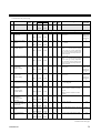
Continued from the previous page.
Register address
No. Name
Iden-
tifier
Chan-
nel
HEX DEC
Digits
Attri-
bute
Struc-
ture
Data range
Factory
set value
38 Integral time
[heat-side]
★ ♣
I1 CH1
·
·
·
CH64
0B5C
·
·
·
0B9B
2908
·
·
·
2971
7 R/W C
PID control or heat/cool PID
control:
0 to 3600 seconds or
0.0 to 1999.9 seconds
(0, 0.0: PD action)
Position proportioning control:
1 to 3600 seconds or
0.1 to 1999.9 seconds
Varies with the setting of the
integral/derivative time decimal point
position selection.
240
39 Derivative time
[heat-side]
★ ♣
D1 CH1
·
·
·
CH64
0B9C
·
·
·
0BDB
2972
·
·
·
3035
7 R/W C
0 to 3600 seconds or
0.0 to 1999.9 seconds
(0, 0.0: PI action)
Varies with the setting of the
integral/derivative time decimal point
position selection.
60
40 Control response
parameter
★ ♣
CA CH1
·
·
·
CH64
0BDC
·
·
·
0C1B
3036
·
·
·
3099
1 R/W C 0: Slow
1: Medium
2: Fast
When the P or PD action is selected, this
setting becomes invalid.
PID control,
Position
proportioning
control: 0
Heat/cool PID
control: 2
41 Proportional band
[cool-side] ★ ♣
P2 CH1
·
·
·
CH64
0C1C
·
·
·
0C5B
3100
·
·
·
3163
7 R/W C
TC/RTD inputs:
1 (0.1) to Input span
(Unit: °C [°F])
Varies with the setting of the decimal
point position selection.
Voltage (V)/current (I) inputs:
0.1 to 1000.0 % of input span
If control is other than heat/cool PID
control, set to RO (Only reading data is
possible).
TC/RTD:
30 (30.0)
V/I: 30.0
42 Integral time
[cool-side]
★ ♣
I2 CH1
·
·
·
CH64
0C5C
·
·
·
0C9B
3164
·
·
·
3227
7 R/W C
0 to 3600 seconds or
0.0 to 1999.9 seconds
(0, 0.0: PD action)
Varies with the setting of the
integral/derivative time decimal point
position selection.
If control is other than heat/cool PID
control, set to RO (Only reading data is
possible).
240
43 Derivative time
[cool-side]
★ ♣
D2 CH1
·
·
·
CH64
0C9C
·
·
·
0CDB
3228
·
·
·
3291
7 R/W C
0 to 3600 seconds or
0.0 to 1999.9 seconds
(0, 0.0: PI action)
Varies with the setting of the
integral/derivative time decimal point
position selection.
If control is other than heat/cool PID
control, set to RO (Only reading data is
possible).
60
★: Parameters which can be used in multi-memory area function
Continued on the next page.

IMR02E04-E1
8
Continued from the previous page.
Register address
No. Name
Iden-
tifier
Chan-
nel
HEX DEC
Digits
Attri-
bute
Struc-
ture
Data range
Factory
set value
44 Overlap/Deadband
★ ♣
V1 CH1
·
·
·
CH64
0CDC
·
·
·
0D1B
3292
·
·
·
3355
7 R/W C
TC/RTD inputs:
−Input span to +Input span
(Unit:°C [°F])
Voltage (V)/current (I) inputs:
−100.0 to +100.0 % of input
span
Minus (−) setting results in overlap.
However, the overlapping range is
within the proportional range.
If control is other than heat/cool PID
control, set to RO (Only reading data is
possible).
0
45 Manual reset ★
MR CH1
·
·
·
CH64
0D1C
·
·
·
0D5B
3356
·
·
·
3419
7 R/W C
−100.0 to +100.0 %
If the integral function is valid, set to
RO (Only reading data is possible).
When integral action (heating or cooling
side) is zero, manual reset value is
added to the control output.
0.0
46 Setting change rate
limiter (up) ★
HH CH1
·
·
·
CH64
0D5C
·
·
·
0D9B
3420
·
·
·
3483
7 R/W C 0 (0.0) to Input span/unit time *
0 (0.0): Unused
0 (0.0)
47 Setting change rate
limiter (down) ★
HL CH1
·
·
·
CH64
0D9C
·
·
·
0DDB
3484
·
·
·
3547
7 R/W C
* Unit time: 60 seconds
(factory set value)
0 (0.0)
48 Area soak time ★ TM CH1
·
·
·
CH64
0DDC
·
·
·
0E1B
3548
·
·
·
3611
7 R/W C 0 minutes 00 seconds to 199 minutes
59 seconds:
RKC communication:
0:00 to 199:59 (min:sec)
Modbus/MECHATROLINK
0 to 11999 seconds
0 hours 00 minutes to 99 hours 59
minutes:
RKC communication:
0:00 to 99:59 (hrs:min)
Modbus/MECHATROLINK
0 to 5999 minutes
Data range of Area soak time can be
selected on the Soak time unit.
Note1
49 Link area number ★ LP CH1
·
·
·
CH64
0E1C
·
·
·
0E5B
3612
·
·
·
3675
7 R/W C 0 to 8
(0: No link)
0
50 Heater break alarm
(HBA) set value
A7 CH1
·
·
·
CH64
0E5C
·
·
·
0E9B
3676
·
·
·
3739
7 R/W C
When CT is CTL-6-P-N:
0.0 to 30.0 A (0.0: Not used)
When CT is CTL-12-S56-10L-N:
0.0 to 100.0 A (0.0: Not used)
If there is no current transformer (CT)
or CT is assigned to “0: None,” set to
RO (Only reading data is possible).
0.0
51 Heater break
determination point
NE CH1
·
·
·
CH64
0E9C
·
·
·
0EDB
3740
·
·
·
3803
7 R/W C
0.0 to 100.0 % of HBA set value
(0.0: Heater break determination is
invalid)
If there is no current transformer (CT) or
CT is assigned to “0: None,” set to RO
(Only reading data is possible).
If Heater break alarm (HBA)
corresponds to “0: Type A,” set to RO
(Only reading data is possible).
30.0
★: Parameters which can be used in multi-memory area function
Note1 RKC communication: 0:00 Modbus/MECHATROLINK: 0
Continued on the next page.

IMR02E04-E1
9
Continued from the previous page.
Register address
No. Name
Iden-
tifier
Chan-
nel
HEX DEC
Digits
Attri-
bute
Struc-
ture
Data range
Factory
set value
52 Heater melting
determination point
NF CH1
·
·
·
CH64
0EDC
·
·
·
0F1B
3804
·
·
·
3867
7 R/W C
0.0 to 100.0 % of HBA set value
(0.0: Heater melting determination
is invalid)
If there is no current transformer (CT) or
CT is assigned to “0: None,” set to RO
(Only reading data is possible).
If Heater break alarm (HBA)
corresponds to “0: Type A,” set to RO
(Only reading data is possible).
30.0
53 PV bias PB CH1
·
·
·
CH64
0F1C
·
·
·
0F5B
3868
·
·
·
3931
7 R/W C −Input span to +Input span 0
54 PV digital filter F1 CH1
·
·
·
CH64
0F5C
·
·
·
0F9B
3932
·
·
·
3995
7 R/W C 0.0 to 100.0 seconds
(0.0: Unused)
0.0
55 PV ratio PR CH1
·
·
·
CH64
0F9C
·
·
·
0FDB
3996
·
·
·
4059
7 R/W C 0.500 to 1.500 1.000
56 PV low input cut-off DP CH1
·
·
·
CH64
0FDC
·
·
·
101B
4060
·
·
·
4123
7 R/W C
0.00 to 25.00 % of input span
If the Square root extraction
corresponds to “0: Unused,” set to RO
(Only reading data is possible).
0.00
57 RS bias *
RB CH1
·
·
·
CH64
101C
·
·
·
105B
4124
·
·
·
4187
7 R/W C −Input span to +Input span 0
58 RS digital filter *
F2 CH1
·
·
·
CH64
105C
·
·
·
109B
4188
·
·
·
4251
7 R/W C 0.0 to 100.0 seconds
(0.0: Unused)
0.0
59 RS ratio *
RR CH1
·
·
·
CH64
109C
·
·
·
10DB
4252
·
·
·
4315
7 R/W C 0.001 to 9.999 1.000
60 Output distribution
selection
DV CH1
·
·
·
CH64
10DC
·
·
·
111B
4316
·
·
·
4379
1 R/W C 0: Control output
1: Distribution output
0
61 Output distribution
bias
DW CH1
·
·
·
CH64
111C
·
·
·
115B
4380
·
·
·
4443
7 R/W C −100.0 to +100.0 % 0.0
62 Output distribution
ratio
DQ CH1
·
·
·
CH64
115C
·
·
·
119B
4444
·
·
·
4507
7 R/W C −9.999 to +9.999 1.000
63 Proportional cycle
time
T0 CH1
·
·
·
CH64
119C
·
·
·
11DB
4508
·
·
·
4571
7 R/W C
0.1 to 100.0 seconds
This item becomes RO (Only reading data
is possible) for the voltage/current output
specification.
This parameter is valid when “0: control
output” has been selected at No.95
“Output assignment.”
Relay contact
output:
20.0
Voltage pulse
output, triac
output and
open collector
output:
2.0
64 Minimum ON/OFF
time of proportioning
cycle
VI CH1
·
·
·
CH64
11DC
·
·
·
121B
4572
·
·
·
4635
7 R/W C
0 to 1000 ms
This item becomes RO (Only reading data
is possible) for the voltage/current output
specification.
0
* Data on RS bias, RS ratio and RS digital filter is that in cascade control or ratio setting.
Continued on the next page.

IMR02E04-E1
10
Continued from the previous page.
Register address
No. Name
Iden-
tifier
Chan-
nel
HEX DEC
Digits
Attri-
bute
Struc-
ture
Data range
Factory
set value
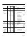
65 Manual manipulated
output value
♣
ON CH1
·
·
·
CH64
121C
·
·
·
125B
4636
·
·
·
4699
7 R/W C
PID control:
Output limiter (low) to
Output limiter (high)
Heat/cool PID control:
−Cool-side output limiter (high)
to +Heat-side output limiter
(high)
Position proportioning control:
When there is feedback resistance
(FBR) input and it does not break:
Output limiter (low) to
Output limiter (high)
When there is no feedback
resistance (FBR) input or the
feedback resistance (FBR) input is
disconnected:
0: Close-side output OFF,
Open-side output OFF
1: Close-side output ON,
Open-side output OFF
2: Close-side output OFF,
Open-side output ON
0.0
66 Area soak time stop
function
RV CH1
·
·
·
CH64
125C
·
·
·
129B
4700
·
·
·
4763
1 R/W C
0: No function
1: Event 1
2: Event 2
3: Event 3
4: Event 4
0
67 EDS mode
(for disturbance 1)
NG CH1
·
·
·
CH64
129C
·
·
·
12DB
4764
·
·
·
4827
1 R/W C 0
68 EDS mode
(for disturbance 2)
NX CH1
·
·
·
CH64
12DC
·
·
·
131B
4828
·
·
·
4891
1 R/W C
0: No function
1: EDS function mode
2: Learning mode
3: Tuning mode
EDS function: External disturbance
suppression function
0
69 EDS value 1
(for disturbance 1)
NI CH1
·
·
·
CH64
131C
·
·
·
135B
4892
·
·
·
4955
7 R/W C −100.0 to
+100.0 % 0.0
70 EDS value 1
(for disturbance 2)
NJ CH1
·
·
·
CH64
135C
·
·
·
139B
4956
·
·
·
5019
7 R/W C 0.0
71 EDS value 2
(for disturbance 1)
NK CH1
·
·
·
CH64
139C
·
·
·
13DB
5020
·
·
·
5083
7 R/W C −100.0 to
+100.0 % 0.0
72 EDS value 2
(for disturbance 2)
NM CH1
·
·
·
CH64
13DC
·
·
·
141B
5084
·
·
·
5147
7 R/W C 0.0
73 EDS transfer time
(for disturbance 1)
NN CH1
·
·
·
CH64
141C
·
·
·
145B
5148
·
·
·
5211
7 R/W C 0 to 3600 seconds or
0.0 to 1999.9 seconds
0
74 EDS transfer time
(for disturbance 2)
NO CH1
·
·
·
CH64
145C
·
·
·
149B
5212
·
·
·
5275
7 R/W C 0
75 EDS action time
(for disturbance 1)
NQ CH1
·
·
·
CH64
149C
·
·
·
14DB
5276
·
·
·
5339
7 R/W C 1
to 3600 seconds 600
Continued on the next page.

IMR02E04-E1
11
Continued from the previous page.
Register address
No. Name
Iden-
tifier
Chan-
nel
HEX DEC
Digits
Attri-
bute
Struc-
ture
Data range
Factory
set value
76 EDS action time
(for disturbance 2)
NL CH1
·
·
·
CH64
14DC
·
·
·
151B
5340
·
·
·
5403
7 R/W C 1
to 3600 seconds 600
77 EDS action wait time
(for disturbance 1)
NR CH1
·
·
·
CH64
151C
·
·
·
155B
5404
·
·
·
5467
7 R/W C 0.0
to 600.0 seconds 0.0
78 EDS action wait time
(for disturbance 2)
NY CH1
·
·
·
CH64
155C
·
·
·
159B
5468
·
·
·
5531
7 R/W C 0.0
79 EDS value learning
times
NT CH1
·
·
·
CH64
159C
·
·
·
15DB
5532
·
·
·
5595
7 R/W C 0 to 10 times
(0: No learning mode)
1
80 EDS start signal NU CH1
·
·
·
CH64
15DC
·
·
·
161B
5596
·
·
·
5659
1 R/W C
0: EDS start signal OFF
1: EDS start signal ON
(for disturbance 1)
2: EDS start signal ON
(for disturbance 2)
0
81 Operation mode EI CH1
·
·
·
CH64
161C
·
·
·
165B
5660
·
·
·
5723
1 R/W C
0: Unused
1: Monitor
2: Monitor + Event function
3: Control
3
82 Startup tuning (ST) ST CH1
·
·
·
CH64
165C
·
·
·
169B
5724
·
·
·
5787
1 R/W C
0: ST unused
1: Execute once *
2: Execute always
* When the startup tuning (ST) is
finished, the setting will automatically
returns to “0: ST unused.”
The startup tuning (ST) function is
activated according to the ST start
condition selected.
If control is position proportioning
control, set to RO (Only reading data is
possible).
0
83 Automatic
temperature rise
learning
Y8 CH1
·
·
·
CH64
169C
·
·
·
16DB
5788
·
·
·
5851
1 R/W C
0: Unused
1: Learning *
* When the automatic temperature rise
learning is finished, the setting will
automatically returns to “0: Unused.”
0
84
Communication
switch for logic
EF CH1
·
·
·
CH16
16DC
·
·
·
16EB
5852
·
·
·
5867
7 R/W M • RKC communication
Least significant digit:
Communication switch 1
2nd digit:
Communication switch 2
3rd digit:
Communication switch 3
4th digit:
Communication switch 4
5th digit to Most significant digit:
Unused
Data 0: OFF 1: ON
• Modbus/MECHATROLINK
Bit data
b0: Communication switch 1
b1: Communication switch 2
b2: Communication switch 3
b3: Communication switch 4
b4 to b15: Unused
Data 0: OFF 1: ON
[Decimal number: 0 to 15]
0
Continued on the next page.

IMR02E04-E1
12
Continued from the previous page.
Register address
No. Name
Iden-
tifier
Chan-
nel
HEX DEC
Digits
Attri-
bute
Struc-
ture
Data range
Factory
set value
85 Unused
16EC
·
·
·
196B
5868
·
·
·
6507
Set data No. 86 or later are for engineering setting [Writable in the STOP mode]
86
Input type XI CH1
·
·
·
CH64
196C
·
·
·
19AB
6508
·
·
·
6571
7 R/W C
0: TC input K
1: TC input J
2: TC input R
3: TC input S
4: TC input B
5: TC input E
6: TC input N
7: TC input T
8: TC input W5Re/W26Re
9: TC input PLII
12: RTD input Pt100
13: RTD input JPt100
14: Current input 0 to 20 mA DC
15: Current input 4 to 20 mA DC
16: Voltage (high) input
0 to 10 V DC
17: Voltage (high) input
0 to 5 V DC
18: Voltage (high) input
1 to 5 V DC
19: Voltage (low) input
0 to 1 V DC
20: Voltage (low) input
0 to 100 mV DC
21: Voltage (low) input
0 to 10 mV DC
22: Feedback resistance input
100 to 150 Ω
23: Feedback resistance input
151 Ω to 6 kΩ
If changed to voltage (high) input from
TC/RTD/current/voltage (low)/feedback
resistance input, select the hardware by
the input selector switch at the side of
the module.
See SRZ Instruction Manual
(IMS01T04-E).
Depends on
model code
When not
specifying: 0
87
Display unit
PU CH1
·
·
·
CH64
19AC
·
·
·
19EB
6572
·
·
·
6635
7 R/W
C
0: °C
1: °F
Use to select the temperature unit for
thermocouple (TC) and RTD inputs.
0
88 Decimal point
position
XU CH1
·
·
·
CH64
19EC
·
·
·
1A2B
6636
·
·
·
6699
7 R/W C 0: No decimal place
1: One decimal place
2: Two decimal places
3: Three decimal places
4: Four decimal places
TC input
:
• K, J, T, E:
Only 0 or 1 can be set.
• R, S, B, N, PLII, W5Re/W26Re:
Only 0 can be set.
RTD input:
Only 0 or 1 can be set.
V/I inputs:
From 0 to 4 can be set.
Depends on
model code
When not
specifying:
TC/RTD: 1
V/I: 1
Continued on the next page.

IMR02E04-E1
13
Continued from the previous page.
Register address
No. Name
Iden-
tifier
Chan-
nel
HEX DEC
Digits
Attri-
bute
Struc-
ture
Data range
Factory
set value
89
Input scale high XV CH1
·
·
·
CH64
1A2C
·
·
·
1A6B
6700
·
·
·
6763
7 R/W C TC/RTD inputs:
Input scale low to
Maximum value of the
selected
input range
Voltage (V)/current (I) inputs:
−19999 to +19999
(However, a span is 20000 or
less.)
Varies with the setting of the decimal point
position
TC/RTD:
Maximum
value of the
selected
input range
V/I: 100.0
90
Input scale low XW CH1
·
·
·
CH64
1A6C
·
·
·
1AAB
6734
·
·
·
6827
7 R/W C
TC/RTD inputs:
Minimum value of the selected
input range to Input scale high
Voltage (V)/current (I) inputs:
−19999 to +19999
(However, a span is 20000 or
less.)
Varies with the setting of the decimal point
position
TC/RTD:
Minimum
value of the
selected
input range
V/I: 0.0
91
Input error
determination point
(high)
AV CH1
·
·
·
CH64
1AAC
·
·
·
1AEB
6828
·
·
·
6891
7 R/W C
Input error determination point
(low limit) to
(Input range high + 5 % of Input
span)
Input range
high + (5 %
of Input span)
92 Input error
determination point
(low)
AW CH1
·
·
·
CH64
1AEC
·
·
·
1B2B
6892
·
·
·
6955
7 R/W C (Input range low − 5 % of Input
span) to
Input error determination point
(high limit)
Input range
low − (5 %
of Input span)
93 Burnout direction BS CH1
·
·
·
CH64
1B2C
·
·
·
1B6B
6956
·
·
·
7019
1 R/W C 0: Upscale
1: Downscale
Valid only when the TC input and voltage
(low) input are selected.
0
94 Square root extraction XH CH1
·
·
·
CH64
1B6C
·
·
·
1BAB
7020
·
·
·
7083
1 R/W C 0: Unused
1: Used
0
95 Output assignment
(Logic output
selection function)
E0 CH1
·
·
·
CH64
1BAC
·
·
·
1BEB
7084
·
·
·
7147
1 R/W C 0: Control output
1: Logic output result
2: FAIL output
0
96 Energized/
De-energized
(Logic output
selection function)
NA CH1
·
·
·
CH64
1BEC
·
·
·
1C2B
7148
·
·
·
7211
1 R/W C 0: Energized
1: De-energized
0
Continued on the next page.

IMR02E04-E1
14
Continued from the previous page.
Register address
No. Name
Iden-
tifier
Chan-
nel
HEX DEC
Digits
Attri-
bute
Struc-
ture
Data range
Factory
set value
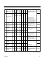
97 Event 1 type XA CH1
·
·
·
CH64
1C2C
·
·
·
1C6B
7212
·
·
·
7275
7 R/W C 0: None
1: Deviation high
(Using SV monitor value)
1
2: Deviation low
(Using SV monitor value)
1
3: Deviation high/low
(Using SV monitor value)
1
4: Band
(Using SV monitor value)
1
5: Process high
1
6: Process low
1
7: SV high
8: SV low
9: Unused
10: MV high [heat-side]
1, 2
11: MV low [heat-side]
1, 2
12: MV high [cool-side]
1
13: MV low [cool-side]
1
14: Deviation high
(Using local SV value)
1
15: Deviation low
(Using local SV value)
1
16: Deviation high/low
(Using local SV value)
1
17: Band (Using local SV value)
1
18: Deviation between channels
high
1
19: Deviation between channels
low
1
20: Deviation between channels
high/low
1
21: Deviation between channels
band
1
1
Event hold action is available.
2
If there is feedback resistance (FBR)
input in position proportioning
control, set to the feedback resistance
(FBR) input value.
Depends on
model code
When not
specifying:
0
98 Event 1
channel setting
FA CH1
·
·
·
CH64
1C6C
·
·
·
1CAB
7276
·
·
·
7339
1 R/W C 1: Channel 1
2: Channel 2
3: Channel 3
4: Channel 4
This function is valid when “deviation
between channels”is selected.
1
99 Event 1 hold action WA CH1
·
·
·
CH64
1CAC
·
·
·
1CEB
7340
·
·
·
7403
1 R/W C
0: OFF
1: Hold action ON
(When power turned on)
2: Re-hold action ON
(When power turned on and SV
changed)
This function is valid when input value,
deviation or manipulated value action
has been selected.
In case of a deviation action, this
function is not available while in remote
mode and while setting changing rate
limiter is working.
Depends on
model code
When not
specifying:
0
100 Event 1 interlock LF CH1
·
·
·
CH64
1CEC
·
·
·
1D2B
7404
·
·
·
7467
1 R/W C 0: Unused
1: Used
0
101 Event 1
differential gap
HA CH1
·
·
·
CH64
1D2C
·
·
·
1D6B
7468
·
·
·
7531
7 R/W C
Deviation, process, set value, or
Deviation action between
channels:
0 to Input span (Unit: °C [°F])
MV: 0.0 to 110.0 %
: TC/RTD:
1
V/I: 0.1
: 0.1
Continued on the next page.

IMR02E04-E1
15
Continued from the previous page.
Register address
No. Name
Iden-
tifier
Chan-
nel
HEX DEC
Digits
Attri-
bute
Struc-
ture
Data range
Factory
set value
102 Event 1 delay timer TD CH1
·
·
·
CH64
1D6C
·
·
·
1DAB
7532
·
·
·
7595
7 R/W C 0 to 18000 seconds 0
103
Force ON of Event 1
action
OA CH1
·
·
·
CH64
1DAC
·
·
·
1DEB
7596
·
·
·
7659
7 R/W C • RKC communication
Least significant digit:
Event output turned on at input
error occurrence
2nd digit:
Event output turned on in
manual mode
3rd digit:
Event output turned on during
the autotuning (AT) function is
being executed
4th digit:
Event output turned on during
the setting change rate limiter is
being operated
5th digit to Most significant digit:
Unused
Data 0: Invalid 1: Valid
• Modbus/MECHATROLINK
Bit data
b0: Event output turned on at input
error occurrence
b1: Event output turned on in
manual mode
b2: Event output turned on during
the autotuning (AT) function is
being executed
b3: Event output turned on during
the setting change rate limiter
is being operated
b4 to b15: Unused
Data 0: Invalid 1: Valid
[Decimal number: 0 to 15]
0
Continued on the next page.

IMR02E04-E1
16
Continued from the previous page.
Register address
No. Name
Iden-
tifier
Chan-
nel
HEX DEC
Digits
Attri-
bute
Struc-
ture
Data range
Factory
set value
104
Event 2 type XB CH1
·
·
·
CH64
1DEC
·
·
·
1E2B
7660
·
·
·
7723
7 R/W C 0: None
1: Deviation high
(Using SV monitor value)
1
2: Deviation low
(Using SV monitor value)
1
3: Deviation high/low
(Using SV monitor value)
1
4: Band
(Using SV monitor value)
1
5: Process high
1
6: Process low
1
7: SV high
8: SV low
9: Unused
10: MV high [heat-side]
1,
2
11: MV low [heat-side]
1,
2
12: MV high [cool-side]
1
13: MV low [cool-side]
1
14: Deviation high
(Using local SV value)
1
15: Deviation low
(Using local SV value)
1
16: Deviation high/low
(Using local SV value)
1
17: Band (Using local SV value)
1
18: Deviation between channels
high
1
19: Deviation between channels
low
1
20: Deviation between channels
high/low
1
21: Deviation between channels
band
1
1
Event hold action is available.
2
If there is feedback resistance (FBR)
input in position proportioning
control, set to the feedback resistance
(FBR) input value.
Depends on
model code
When not
specifying: 0
105 Event 2
channel setting
FB CH1
·
·
·
CH64
1E2C
·
·
·
1E6B
7724
·
·
·
7787
1 R/W C 1: Channel 1
2: Channel 2
3: Channel 3
4: Channel 4
This function is valid when “deviation
between channels”is selected.
1
106 Event 2 hold action
WB CH1
·
·
·
CH64
1E6C
·
·
·
1EAB
7788
·
·
·
7851
1 R/W C
0: OFF
1: Hold action ON
(When power turned on)
2: Re-hold action ON
(When power turned on and SV
changed)
This function is valid when input value,
deviation or manipulated value action
has been selected.
In case of a deviation action, this
function is not available while in remote
mode and while setting changing rate
limiter is working.
Depends on
model code
When not
specifying: 0
107 Event 2 interlock
LG CH1
·
·
·
CH64
1EAC
·
·
·
1EEB
7852
·
·
·
7915
1 R/W C 0: Unused
1: Used
0
108
Event 2
differential gap
HB CH1
·
·
·
CH64
1EEC
·
·
·
1F2B
7916
·
·
·
7979
7 R/W C
Deviation, process, set value, or
Deviation action between
channels:
0 to Input span (Unit: °C [°F])
MV: 0.0 to 110.0 %
: TC/RTD:
1
V/I: 0.1
: 0.1
Continued on the next page.

IMR02E04-E1
17
Continued from the previous page.
Register address
No. Name
Iden-
tifier
Chan-
nel
HEX DEC
Digits
Attri-
bute
Struc-
ture
Data range
Factory
set value
109
Event 2 delay timer
TG CH1
·
·
·
CH64
1F2C
·
·
·
1F6B
7980
·
·
·
8043
7 R/W C 0 to 18000 seconds 0
110
Force ON of Event 2
action
OB CH1
·
·
·
CH64
1F6C
·
·
·
1FAB
8044
·
·
·
8107
7 R/W C
• RKC communication
Least significant digit:
Event output turned on at input
error occurrence
2nd digit:
Event output turned on in
manual mode
3rd digit:
Event output turned on during
the autotuning (AT) function is
being executed
4th digit:
Event output turned on during
the setting change rate limiter is
being operated
5th digit to Most significant digit:
Unused
Data 0: Invalid 1: Valid
• Modbus/MECHATROLINK
Bit data
b0: Event output turned on at input
error occurrence
b1: Event output turned on in
manual mode
b2: Event output turned on during
the autotuning (AT) function is
being executed
b3: Event output turned on during
the setting change rate limiter
is being operated
b4 to b15: Unused
Data 0: Invalid 1: Valid
[Decimal number: 0 to 15]
0
Continued on the next page.

IMR02E04-E1
18
Continued from the previous page.
Register address
No. Name
Iden-
tifier
Chan-
nel
HEX DEC
Digits
Attri-
bute
Struc-
ture
Data range
Factory
set value
111
Event 3 type XC CH1
·
·
·
CH64
1FAC
·
·
·
1FEB
8108
·
·
·
8171
7 R/W C
0: None
1: Deviation high
(Using SV monitor value)
1
2: Deviation low
(Using SV monitor value)
1
3: Deviation high/low
(Using SV monitor value)
1
4: Band
(Using SV monitor value)
1
5: Process high
1
6: Process low
1
7: SV high
8: SV low
9: Temperature rise completion
10: MV high [heat-side]
1,
2
11: MV low [heat-side]
1,
2
12: MV high [cool-side]
1
13: MV low [cool-side]
1
14: Deviation high
(Using local SV value)
1
15: Deviation low
(Using local SV value)
1
16: Deviation high/low
(Using local SV value)
1
17: Band (Using local SV value)
1
18: Deviation between channels
high
1
19: Deviation between channels
low
1
20: Deviation between channels
high/low
1
21: Deviation between channels
band
1
1
Event hold action is available.
2
If there is feedback resistance (FBR)
input in position proportioning
control, set to the feedback resistance
(FBR) input value.
Depends on
model code
When not
specifying: 0
112 Event 3
channel setting
FC CH1
·
·
·
CH64
1FEC
·
·
·
202B
8172
·
·
·
8235
1 R/W C 1: Channel 1
2: Channel 2
3: Channel 3
4: Channel 4
This function is valid when “deviation
between channels”is selected.
1
113 Event 3 hold action
WC CH1
·
·
·
CH64
202C
·
·
·
206B
8236
·
·
·
8299
1 R/W C
0: OFF
1: Hold action ON
(When power turned on)
2: Re-hold action ON
(When power turned on and SV
changed)
This function is valid when input value,
deviation or manipulated value action
has been selected.
In case of a deviation action, this
function is not available while in remote
mode and while setting changing rate
limiter is working.
Depends on
model code
When not
specifying: 0
114
Event 3 interlock
LH CH1
·
·
·
CH64
206C
·
·
·
20AB
8300
·
·
·
8363
1 R/W C 0: Unused
1: Used
0
115 Event 3
differential gap
HC CH1
·
·
·
CH64
20AC
·
·
·
20EB
8364
·
·
·
8427
7 R/W C
Deviation, process, set value,
Deviation action between
channels, or Temperature rise
completion:
0 to Input span (Unit: °C [°F])
MV: 0.0 to 110.0 %
: TC/RTD:
1
V/I: 0.1
: 0.1
Continued on the next page.

IMR02E04-E1
19
Continued from the previous page.
Register address
No. Name
Iden-
tifier
Chan-
nel
HEX DEC
Digits
Attri-
bute
Struc-
ture
Data range
Factory
set value
116 Event 3 delay timer
TE CH1
·
·
·
CH64
20EC
·
·
·
212B
8428
·
·
·
8491
7 R/W C 0 to 18000 seconds
If Event 3 corresponds to “9:
Temperature rise completion,” the Event
3 delay timer becomes the temperature
rise completion soak time.
0
117 Force ON of Event 3
action
OC CH1
·
·
·
CH64
212C
·
·
·
216B
8492
·
·
·
8555
7 R/W C • RKC communication
Least significant digit:
Event output turned on at input
error occurrence
2nd digit:
Event output turned on in
manual mode
3rd digit:
Event output turned on during
the autotuning (AT) function is
being executed
4th digit:
Event output turned on during
the setting change rate limiter is
being operated
5th digit to Most significant digit:
Unused
Data 0: Invalid 1: Valid
• Modbus/MECHATROLINK
Bit data
b0: Event output turned on at input
error occurrence
b1: Event output turned on in
manual mode
b2: Event output turned on during
the autotuning (AT) function is
being executed
b3: Event output turned on during
the setting change rate limiter
is being operated
b4 to b15: Unused
Data 0: Invalid 1: Valid
[Decimal number: 0 to 15]
0
Continued on the next page.

IMR02E04-E1
20
Continued from the previous page.
Register address
No. Name
Iden-
tifier
Chan-
nel
HEX DEC
Digits
Attri-
bute
Struc-
ture
Data range
Factory
set value
118 Event 4 type
XD CH1
·
·
·
CH64
216C
·
·
·
21AB
8556
·
·
·
8619
7 R/W C
0: None
1: Deviation high
(Using SV monitor value)
1
2: Deviation low
(Using SV monitor value)
1
3: Deviation high/low
(Using SV monitor value)
1
4: Band
(Using SV monitor value)
1
5: Process high
1
6: Process low
1
7: SV high
8: SV low
9: Control loop break alarm
(LBA)
10: MV high [heat-side]
1,
2
11: MV low [heat-side]
1,
2
12: MV high [cool-side]
1
13: MV low [cool-side]
1
14: Deviation high
(Using local SV value)
1
15: Deviation low
(Using local SV value)
1
16: Deviation high/low
(Using local SV value)
1
17: Band (Using local SV value)
1
18: Deviation between channels
high
1
19: Deviation between channels
low
1
20: Deviation between channels
high/low
1
21: Deviation between channels
band
1
1
Event hold action is available.
2
If there is feedback resistance (FBR)
input in position proportioning
control, set to the feedback resistance
(FBR) input value.
Depends on
model code
When not
specifying: 0
119 Event 4
channel setting
FD CH1
·
·
·
CH64
21AC
·
·
·
21EB
8620
·
·
·
8683
1 R/W C 1: Channel 1
2: Channel 2
3: Channel 3
4: Channel 4
This function is valid when “deviation
between channels”is selected.
1
120 Event 4 hold action
WD CH1
·
·
·
CH64
21EC
·
·
·
222B
8684
·
·
·
8747
1 R/W C
0: OFF
1: Hold action ON
(When power turned on)
2: Re-hold action ON
(When power turned on and SV
changed)
This function is valid when input value,
deviation or manipulated value action
has been selected.
In case of a deviation action, this
function is not available while in remote
mode and while setting changing rate
limiter is working.
Depends on
model code
When not
specifying: 0
121 Event 4 interlock
LI CH1
·
·
·
CH64
222C
·
·
·
226B
8748
·
·
·
8811
1 R/W C 0: Unused
1: Used
0
Continued on the next page.
La pagina si sta caricando...
La pagina si sta caricando...
La pagina si sta caricando...
La pagina si sta caricando...
La pagina si sta caricando...
La pagina si sta caricando...
La pagina si sta caricando...
La pagina si sta caricando...
La pagina si sta caricando...
La pagina si sta caricando...
La pagina si sta caricando...
La pagina si sta caricando...
La pagina si sta caricando...
La pagina si sta caricando...
La pagina si sta caricando...
La pagina si sta caricando...
La pagina si sta caricando...
La pagina si sta caricando...
La pagina si sta caricando...
La pagina si sta caricando...
La pagina si sta caricando...
La pagina si sta caricando...
La pagina si sta caricando...
La pagina si sta caricando...
-
 1
1
-
 2
2
-
 3
3
-
 4
4
-
 5
5
-
 6
6
-
 7
7
-
 8
8
-
 9
9
-
 10
10
-
 11
11
-
 12
12
-
 13
13
-
 14
14
-
 15
15
-
 16
16
-
 17
17
-
 18
18
-
 19
19
-
 20
20
-
 21
21
-
 22
22
-
 23
23
-
 24
24
-
 25
25
-
 26
26
-
 27
27
-
 28
28
-
 29
29
-
 30
30
-
 31
31
-
 32
32
-
 33
33
-
 34
34
-
 35
35
-
 36
36
-
 37
37
-
 38
38
-
 39
39
-
 40
40
-
 41
41
-
 42
42
-
 43
43
-
 44
44


RKC INSTRUMENT COM-MY Communication Data List
- Tipo
- Communication Data List
in altre lingue
- English: RKC INSTRUMENT COM-MY
Documenti correlati
-
RKC INSTRUMENT SRZ Communication Instruction Manual
-
-
-
-
-
-
-
-
-