ProLights PANORAMAIPSPOT Manuale utente
- Categoria
- Proiettori
- Tipo
- Manuale utente

USER MANUAL
MANUALE UTENTE
PANORAMAIPSPOT
HYBRID MOVING
EN - IT

All rights reserved by Music & Lights S.r.l. No part of this instruction manual may be
reproduced in any form or by any means for any commercial use.
In order to improve the quality of products, Music&Lights S.r.l. reserves the right to modify the
characteristics stated in this instruction manual at any time and without prior notice.
All revisions and updates are available in the ‘manuals’ section on site www.musiclights.it
REV. 01-09/18

1
PANORAMAIPSPOT
Packing content
• PANORAMAIPSPOT
• Mount bracket
• Power supply cable and signal cable
• Safety rope
• User manual
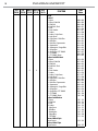
TABLE OF CONTENTS
Safety
General instructions
Warnings and installation precautions
1 Introduction
1. 1 Description
1. 2 Technical specications
1. 3 Operating elements and connections
2 Installation
2. 1 Mounting
3 Functions and settings
3. 1 Operation
3. 2 Basic
3. 3 Menu structure
3. 4 Connect
DMX address
DMX Mode
Wireless
Artnet
RDM
3. 5 DMX Addressing
3. 6 Connection of the DMX line
3. 7 Construction of the DMX termination
3. 8 DMX Channel
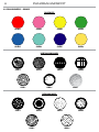
3. 9 Gobos
3. 10 Setup
3. 11 Advanced
3. 12 Information
3. 13 Automatic Mode
4 Maintenance
4. 1 Maintenance and cleaning the unit
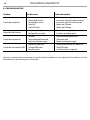
4. 2 Trouble shooting
2
2
3
3
6
7
8
8
9
11
11
11
11
11
12
12
13
13
14
22
23
24
25
26
29
30

PANORAMAIPSPOT
2
WARNING! Before carrying out any operations with the unit, carefully read this instruction
manual and keep it with cure for future reference. It contains important information about
the installation, usage and maintenance of the unit.
SAFETY
General instruction
• The products referred to in this manual conform to the European Community Directives and are there-
fore marked with .
• The unit is supplied with hazardous network voltage (230V~). Leave servicing to skilled personnel only.
Never make any modications on the unit not described in this instruction manual, otherwise you will
risk an electric shock.
• Connection must be made to a power supply system tted with ecient earthing (Class I appliance ac-
cording to standard EN 60598-1). It is, moreover, recommended to protect the supply lines of the units
from indirect contact and/or shorting to earth by using appropriately sized residual current devices.
• The connection to the main network of electric distribution must be carried out by a qualied electrical
installer. Check that the main frequency and voltage correspond to those for which the unit is designed
as given on the electrical data label.
• This unit is not for home use, only professional applications.
• Never use the xture under the following conditions:
- in places subject to vibrations or bumps;
- in places with an ambient temperature of over 45°C.
• Make certain that no inammable liquids, water or metal objects enter the xture.
• Do not dismantle or modify the xture.
• All work must always be carried out by qualied technical personnel. Contact the nearest sales point for
an inspection or contact the manufacturer directly.
• If the unit is to be put out of operation denitively, take it to a local recycling
plant for a disposal which is not harmful to the environment.
Warnings and installation precautions
• If this device will be operated in any way dierent to the one described in this manual, it may suer
damage and the guarantee becomes void. Furthermore, any other operation may lead to dangers like
short circuit, burns, electric shock, etc.
• Before starting any maintenance work or cleaning the projector, cut o power from the main supply.
• Always additionally secure the projector with the safety rope. When carrying out any work, always com-
ply scrupulously with all the regulations (particularly regarding safety) currently in force in the country
in which the xture’s being used.
• For inside use only. Not designed for outside use.
• The minimum distance between the xture and surrounding walls must be more than 50 cm and the
air vents at the housing must not be covered in any case.
• Install the xture in a well ventilated place.
• Keep any inammable material at a safe distance from the xture.
• The maximum temperature that can be reached on the external surface of the tting, in a thermally
steady state, is high. After power o, please cool down over 15 minutes.
• Shields, lenses or ultraviolet screens shall be changed if they have become damaged to such an extent
that their eectiveness is impaired.
• The lamp (LED) shall be changed if it has become damaged or thermally deformed.
• Never look directly at the light beam. Please note that fast changes in lighting, e. g. ashing light, may
trigger epileptic seizures in photosensitive persons or persons with epilepsy.

3
PANORAMAIPSPOT
- 1 - INTRODUCTION
1.1 TECHNICAL SPECIFICATIONS
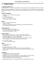
PANORAMAIPSPOT is a powerful and exible IP rated moving LED spot designed to deliver a stunning
brightness level, all packaged in a compact housing. Equipped with a 1:10 zoom and a complete feature
set, the PANORAMAIPSPOT really stands out in any environment be it festivals, arenas or large outdoor
events.
LIGHT SOURCE
• Source: 420W high-power white LED
• CT: 7.000K
• Lux: (5°) 21’362lx @5 m
• Lux: (50°) 1’173lx @5 m full
• Source life expectancy: >20.000 h
OPTICS
• Zoom: 5°-50° motorised linear zoom
• Lens diameter: 120mm
• Lens type: HD anti-reection lenses with achromatic coating
• Focus: motorised with auto-focus
COLOUR SYSTEM
• Colour mixing: linear CMY
• CTC: linear CTO correction 2700 ~ 6000 K
• Colour wheel: 8 dichroic lters + open
DYNAMIC EFFECTS
• Rotating gobos: 7 rotating gobos + open, interchangeable, indexing
• Gobo size: outer: 26 mm - image: 19 mm - max thickness: 2 mm
• Fixed gobos: 6 xed gobos + open, interchangeable
• Gobo size: outer: 26 mm - image: 19 mm - max thickness: 0.5 mm
• Circular prism: 3f with bi-directional rotation, indexing
• Frost: linear 0 - 100% frost lter
• Iris: 5-100% motorised linear iris
BODY
• Pan angle: 540 - 630°
• Tilt angle: 233°
• Pan/Tilt resolution: 8 / 16 bit
• Feedback: automatic repositioning after accidental movement
• Body: aluminium structure with hi-resistance polycarbonate cover
• Body colour: black
CONTROL
• Protocols: DMX512, RDM, Art-Net, W-DMX
• DMX channels: 19 / 21 / 28 / 29 / 36channel
• W-DMX: included, wireless solution receiver
• RDM: RDM ready for xture remote monitor and settings
• Display: LCD high resolution colour display
• Firmware upgrade: yes, via USB - DMX interface (UPBOX2) not included

PANORAMAIPSPOT
4
• Hibernation: power safe mode when lost DMX
ELECTRONICS
• Dimmer: linear 0 ~ 100% electronic dimmer
• Strobe / shutter: 1-28 Hz, electronic
• Battery backup: battery backup for user operation without connecting to the main power
• Operating temperature: -20° ~ +45°
ELECTRICAL
• Power supply: 100-240 V – 50/60 Hz
• Power consumption (at 230 V): 492W
• Power consumption (at 120 V): 501W
PHYSICAL
• Cooling: combination of heat pipe cooling system and low noise fan
• Sospension and xing: any position with quick-lock omega brackets
• Pan / tilt lock: pan / tilt locking for transportation and maintenance
• Signal connection: Amphenol XLR 5p IN/OUT connectors
• Data connection: Art-Net RJ45 IN/OUT
• Power connection: Seetronic powerCON waterproof IN/OUT connectors
• IP rating: 65 for temporary outdoor application, not for xed installation
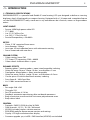
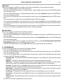
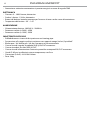
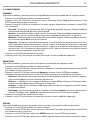
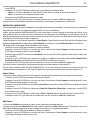
• Dimensions (WxHxD): 441x740x316mm
• Weight: 38kg

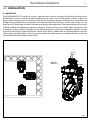
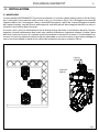
474,4
420
312
740,2
5
PANORAMAIPSPOT
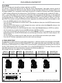
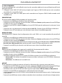
Fig.1
Technical drawing

1
2
3
5
6
4
8 7
109
11 12
A
B
PANORAMAIPSPOT
6
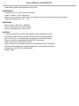
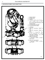
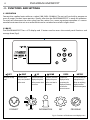
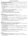
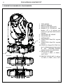
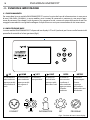
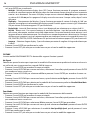
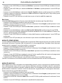
1.2 OPERATING ELEMENTS AND CONNECTIONS
1. MOVING HEAD
2. ROTARY ARM
3. HANDLE
4. CONTROL PANEL with LCD display
and 5 button used to access
the control panel functions and
manage them.
5. LED INDICATOR "W-DMX"
6. LED INDICATOR POWER
7. ANTENNA
8. EtherCON connector Signal IN/
OUT
9. EtherCON connector Signal IN/
OUT
10. POWER IN (PowerCON TRUE
IN): for connection to a socket
(100-240V~/50-60Hz) via the
supplied mains cable.
11. DMX IN (5-pole XLR):
1 = ground, 2 = DMX-, 3 = DMX+,
4 N/C, 5 N/C
12. DMX OUT (5-pole XLR):
1 = ground, 2 = DMX-, 3 = DMX+,
4 N/C, 5 N/C
Fig.2
View A
View B

7
PANORAMAIPSPOT
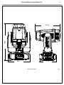
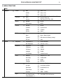
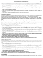
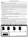
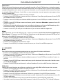
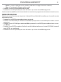
Fig.3
CLAMP
SAFETY
CABLE
OMEGA
BRACKETS
- 2 - INSTALLATION
2.1 MOUNTING
The PANORAMAIPSPOT may be set up on a solid and even surface. By means of the xing facilities of the
baseplate, the unit can also be mounted upside down to a cross arm. The base plate is shown in g.3. For
xing, stable mounting clips are required. According to the gure, the bolts of the brackets are placed into
the openings provided in the base plate and turned clockwise until they lock (to the stop). Always ensure
that the unit is rmly xed to avoid vibration and slipping while operating. The mounting place must be of
sucient stability and be able to support a weight of 10 times of the unit’s weight. When carrying out any
installation, always comply scrupulously with all the regulations (particularly regarding safety) currently
in force in the country in which the xture’s being used. Always additionally secure the projector with the
safety rope from falling down. For this purpose, fasten the safety rope at a suitable position so that the
maximum fall of the projector will be 20 cm.

PANORAMAIPSPOT
8
- 3 - FUNCTIONS AND SETTINGS
3.1 OPERATION
Connect the supplied main cable to a socket (100-240V~/50-60Hz). The unit will run built-in program to
reset all motors to their home position. Shortly after that the PANORAMAIPSPOT is ready for operation.
To switch o, disconnect the mains plug from the socket. For a more convenient operation it is recom-
mended to connect the unit to a socket which can be switched on and o via light switch.
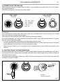
3.2 BASIC
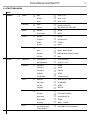
The PANORAMAIPSPOT has a LCD display and 5 button used to access the control panel functions and
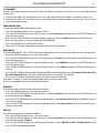
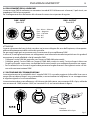
manage them (g.4).
Fig.4 - Functions of the buttons and display icons
LEFT RIGHT UP DOWN ENTER BATTERY
Return to the top
level
Commute from
units, tens, hundred
in the menu
Increases the value
displayed or passes
to the previous item
in a menu
Decreases the value
displayed or passes
to the next item in
the menu
Conrms the
displayed value,
or activates the
displayed function,
or enters the
successive menu
Used to activate the
backup battery. It
allows to switching
display interface
without main power
SPOT
CONNECT
LIGHT
INFORMATION
SET
PROGRAM

9
PANORAMAIPSPOT
3.3 MENU STRUCTURE
MENU
1 CONNECT
ð
Address
ð
DMX
ð
Value (1-512)
W-DMX
ð
Value (1-512)
Artnet
ð
Value (1-512)
DMX Mode
ð
Mode
ð
Standard; Extended; Basic-8bit; Basic-16bit;
Extended-16bit; User;
Edit User
ð
Max Channel=XX / PAN= CH01
Wireless
ð
DMX Out
ð
OFF/ON
Reset Connect
ð
NO/YES
Ethernet
ð
DMX Out
ð
OFF/ON
IP Address
ð
xxx.xxx.xxx.xxx
IP Mask
ð
255.0.0.0
Universe
ð
xxxxxx
RDM ID
ð
Name
ð
Fixture ID Name
Mode
ð
Mode1 / Mode2 (Model)
Password
ð
050 (unlocks the following settings)
PID Code
ð
xxxxx
2 SET UP
ð
Temperature
ð
Temperature C/F
ð
Celsius/Fahrenheit
Max Temperature
ð
Value (60°~90° C)
Movement
ð
Pan Reverse
ð
YES/NO
Tilt Reverse
ð
YES/NO
Pan Degree
ð
540/630
Feedbacks
ð
YES/NO
Pan/Tilt Mode
ð
Standard/Smooth
Screen
ð
Backlight
ð
Always On / 01 ~ 99m
Flip Display
ð
YES/NO/AUTO
Key Lock
ð
ON/OFF
Language
ð
EN/FR/SP...
Fixture
ð
Fans Mode
ð
Auto Speed/High Speed
No Signal
ð
Close/Hold/Auto/Music
Hibernation
ð
Disable/Min (01-99)
Theatre Mode
ð
YES/NO
Frequency
ð
600Hz ... (1200Hz)
Adjust
ð
Pan, Pan Fine, Tilt, Tilt
Fine, Pan&Tilt Speed,
Shutter, Dimmer, [...]
ð
Value (000-255) for each function

PANORAMAIPSPOT
10
3 ADVANCED
ð
Reset
ð
All
Pan & Tilt
Others
Calibration
ð
Password
ð
050 (unlocks the following settings)
Pan
ð
Value
Others
Reload Default
ð
Basic Reload
ð
ON/OFF
Program Reload
ð
ON/OFF
Password
ð
050 (unlocks the following settings)
Private Reload
ð
ON/OFF
All Reload
ð
ON/OFF
4 INFORMATION
ð
Time I nfo.
Current XXXX(Hours)
Fixture Life XXXX(Hours)
Temperature Near Lamp Temp (depends on xture)
Fans Speed Near Lamp Fan (depends on xture)
Channel Value Pan......
Error Message Pan,Tilt,.......
Fixture Model xxxxxx
Software Ver. 1U01 V1.0.00.......
5 STAND ALONE
ð
Play
ð
DMX Receive
Slave Receive
ð
Part 1-2-3 Receive
Static
ð
xxx Scene
Sequence
ð
Alone/Master
Music
ð
Alone/Master
Mic Sens.
ð
Value (00-99%)
Select Chase
ð
Chase Part 1
ð
Chase 1 - Chase 8
Chase Part 2 Chase 1 - Chase 8
Chase Part 3
ð
Chase 1 - Chase 8
Edit Chase
ð
Chase 1
ð
Step 1 - 64
Chase 2 Step 1 - 64
....
Chase 8
ð
Step 1 - 64
Edit Scenes
ð
Edit Scenes 001
ð
Pan/Pan Fine/Tilt/Tilt Fine/...
Edit Scenes ...
ð
Pan/Tilt/CMY, Gobo1...
Edit Scenes 250
ð
Pan/Tilt/CMY, Gobo1...
Scenes Record
ð
Sc XX - Sc XX

11
PANORAMAIPSPOT
3.4 CONNECT
Several units may be interconnected in order to control all further slave units to the same eect of the
master unit.
1. Connect the DMX OUT of the master unit via 5-pole XLR cable to the DMX IN of the rst slave unit.
2. Connect the DMX OUT of the rst slave unit to the DMX IN of the second slave unit, etc. until all units
are connected in a chain.
DMX ADDRESSING
To enter the DMX mode, follow these steps:
• Press the ENTER button to access the main menu.
• Press the UP/DOWN button to scroll the menu, select the Connect icon, then press the ENTER button to
enter the next menu.
• Press the UP/DOWN button to scroll through the menu, select the Address and press the ENTER key.
• Press the arrow keys to select the desired value (001-512).
• Press the ENTER key to conrm the setting.
• Press the LEFT button repeatedly to exit the menu and save changes.
DMX MODE
The PANORAMAIPSPOT has 5 DMX channel congurations which can be accessed from the control panel.
• Press the ENTER button to access the main menu.
• Press the UP/DOWN button to scroll the menu, select the Connect icon, then press the ENTER button to
enter the next menu.
• Press the UP/DOWN button to scroll through the menu, select DMX Mode and press the ENTER button to
enter the next menu.
• Press the UP/DOWN button to scroll through the menu, select Mode and press ENTER to conrm your
choice.
• Use the UP/DOWN button to select the desired DMX channel conguration (Standard, Extended, Basic-8bit,
Basic-16bit,Extended2, User), then press the ENTER button to conrm your choice.
• Press the LEFT button repeatedly to exit the menu and save changes.
The tables on page 14 show the mode of operation and their values DMX.
The unit is equipped with 3/5-pole XLR connections.
WIRELESS
To enable wireless control mode, proceed as follows:
• Press the ENTER button to access the main menu.
• Press the UP/DOWN button to scroll the menu, select the Connect icon, then press the ENTER button to
enter the next menu Wireless.
• Press the UP/DOWN button to scroll through the menu, select Receive on/o and press ENTER to activate
the wireless mode.
• Press the UP/DOWN button to scroll through the menu, select Reset Connect to reset the wireless con-
nection of the unit.
ARTNET
To enable Artnet mode, proceed as follows:
• Press the ENTER button to access the main menu.
• Press the UP/DOWN button to scroll the menu, select the Connect icon, then press the ENTER button to
enter the next menu Ethernet.
• Press the UP/DOWN button to scroll through the menu, select DMX Out, IP Address, IP Mask, Universe, and
press ENTER to activate the mode.

PANORAMAIPSPOT
12
ID and RDM
With this function you can call up various submenus via RDM.
This device is RDM ready. RDM stands for “Remote Device Management” and makes remote control of
devices connected to the DMX-bus possible. Manual settings like adjusting the DMX starting address are
no longer needed. This is especially useful when the device is installed in a remote area. RDM is integrated
in DMX without inuencing the connections. The RDM-data is transmitted via the standard XLR-poles 1
and 2 – new DMX-cables are not necessary. RDM ready and conventional DMX devices can be operated
in one DMX line. The RDM protocol sends own packages in the DMX512 data feed and does not inuence
conventional devices. If DMX splitters are used and RDM control is to be used, these splitters must sup-
port RDM. The number and type of RDM parameters depend on the RDM controller (not included) is used.
• Press the ENTER button to access the main menu.
• Press the UP/DOWN button to scroll the menu, select the Set icon, then press the ENTER button to enter
the next menu.
• Press the UP/DOWN button to scroll through the menu, and then select the Fixture ID and press the
ENTER button to enter the next menu.
• Press UP/DOWN button to scroll through the menu, then select Password and press ENTER to conrm.
• Use the arrow keys to enter the password 050 and press ENTER to conrm.
• Once you have entered your password, you can set the PID Code, necessary to control the unit with the
RDM protocol. Press the UP/DOWN button to scroll through the menu, select PID Code and press EN-
TER to conrm.
• Use the arrow keys to enter the PID Code, then press the ENTER button to conrm your choice.
• Press the LEFT button repeatedly to exit the menu and save changes.
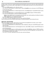
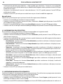
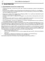
3.5 DMX ADDRESSING
For operation via light control unit with DMX512 protocol, is sucient connect the controller to PANORA-
MAIPSPOT. To able to operate the PANORAMAIPSPOT with a light controller, adjust the DMX start address
for the rst a DMX channel. If e. g. address 33 on the controller is provided for controlling the function of
the rst DMX channel, adjust the start address 33 on the PANORAMAIPSPOT. The other functions of the
light eect panel are then automatically assigned to the following addresses.
An example with the start address 33 is shown below:
Number of
DMX channels
Start address
(example)
DMX Address
occupied
Next possible start
address for unit No. 1
Next possible start
address for unit No. 2
Next possible start
address for unit No. 3
21 33 33-53 54 74 95
DMX Address: 102DMX Address: 56DMX Address: 33 DMX Address: 79
Fig.5 - Example 23 DMX channels conguration
. . . . . . . . . . . .
DMX512 Controller

13
PANORAMAIPSPOT
3.6 CONNECTION OF THE DMX LINE
DMX connection employs standard XLR connectors. Use shielded pair-twisted cables with 120Ω imped-
ance and low capacity.
The following diagram shows the connection mode:
Fig.6
DMX - OUTPUT
XLR socket
DMX - INPUT
XLR plug
Pin1 : GND - Shield
Pin2 : - Negative
Pin3 : + Positive
Pin4 : N/C
Pin5 : N/C
ATTENTION
The screened parts of the cable (sleeve) must never be connected to the system’s earth, as this would
cause faulty xture and controller operation.
Over long runs can be necessary to insert a DMX level matching amplier.
For those connections the use of balanced microphone cable is not recommended because it cannot
transmit control DMX data reliably.
• Connect the controller DMX input to the DMX output of the rst unit.
• Connect the DMX output to the DMX input of the following unit. Connect again the output to the input
of the following unit until all the units are connected in chain.
• When the signal cable has to run longer distance is recommended to insert a DMX termination on the
last unit.
3.7 CONSTRUCTION OF THE DMX TERMINATION
The termination avoids the risk of DMX 512 signals being reected back along the cable when they reach-
es the end of the line: under certain conditions and with certain cable lengths, this could cause them to
cancel the original signals.
The termination is prepared by soldering a 120Ω 1/4 W resistor between pins 2 and 3 of the 5-pin male XLR
connector, as shown in gure.
Fig.7
Example:
5 pin XLR connector

PANORAMAIPSPOT
14
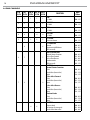
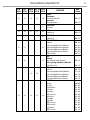
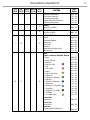
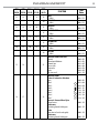
3.8 DMX CHANNELS
STD EXT BAS-8 BAS-16 EXT2
FUNCTION
DMX
Value
28 Ch 29 Ch 19 Ch 21 Ch 36 Ch
1 1 1 1 1
PAN
0~100% 000 - 255
2 2 2 2
PAN FINE
0~100% 000 - 255
3 3 2 3 3
TILT
0~100% 000 - 255
4 4 4 4
TILT FINE
0~100% 000 - 255
5 5 3 5 5
P/T SPEED
Fastest to slowest 000 - 255
6 6
P/T FUNCTION
Normal
Movement with Blackout
TBD (not used)
000 - 015
016 - 031
032 - 255
6 7 7
SHUTTER FUNCTION
Normal Shutter Functions
Pulse-eect Forward
Pulse-eect Reverse
Random strobe
TBD (not used)
000 - 015
016 - 031
032 - 047
048 - 063
064 - 255
7 8 8
SHUTTER
Normal Shutter Functions
Close
Strobe Rate (slow to fast)
Open
Pulse-eect Forward
Close
Strobe Rate (slow to fast)
Open
Pulse-eect Reverse
Close
Strobe Rate (slow to fast)
Open
Random Strobe
Close
Strobe Rate (slow to fast)
Open
000 - 031
032 - 223
224 - 255
000 - 031
032 - 223
224 - 255
000 - 031
032 - 223
224 - 255
000 - 031
032 - 223
224 - 255
4 6
SHUTTER
Shutter closed
No function (shutter open)
Strobe eect slow to fast
000 - 031
032 - 063
064 - 095

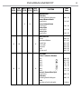
15
PANORAMAIPSPOT
STD EXT BAS-8 BAS-16 EXT2
FUNCTION
DMX
Value
28 Ch 29 Ch 19 Ch 21 Ch 36 Ch
4 6
No function (shutter open)
Pulse-eect in sequences
No function (shutter open)
Random strobe eect slow to fast
No function (shutter open)
096 - 127
128 - 159
160 - 191
192 - 223
224 - 255
8 9 5 7 9
DIMMER
Dimmer (0% to 100%) 000 - 255
10
DIMMER FINE
White (0% to 100%) 000 - 255
9 10 11
COLOR FUNCTION
Indexed
Indexed with Blackout
Forward Spin
Reverse Spin
Continuous
Color Bounce (from slow to fast)
TBD (not used)
000 - 015
016 - 031
032 - 047
048 - 063
064 - 079
080 - 111
112 - 255
10 11 12
COLOR
Indexed - Indexed w. Blackout - Bounce
1 - Open
2 - Open / Dark Red
3 - Dark Red
4 - Dark Red / Pink
5 - Pink
6 - Pink / Amber
7 - Amber
8 - Amber / Light Green
9 - Light Green
10 - Light Green / Dark Blue
11 - Dark Blue
12 - Dark Blue / Aquamarine
13 - Aquamarine
14 - Aquamarine / Congo Blue
15 - Congo Blue
16 - Congo Blue / CTC 3200 K
17 - CTC 3200 K
18 - CTC 3200 K / Open
Forward Spin
Stop to fastest
Reverse Spin
Stop to fastest
Continuous
Positioning from 0 -360 degrees
000 - 013
014 - 027
028 - 041
042 - 055
056 - 069
070 - 083
084 - 097
098 - 111
112 - 125
126 - 139
140 - 153
154 - 167
168 - 181
182 - 195
196 - 209
210 - 223
224 - 237
238 - 255
000 - 255
000 - 255
000 - 255

PANORAMAIPSPOT
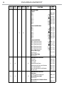
16
STD EXT BAS-8 BAS-16
EXT2
FUNCTION
DMX
Value
28 Ch 29 Ch 19 Ch 21 Ch
36 Ch
6 8
COLOR
Indexed
1 - Open
2 - Open / Dark Red
3 - Dark Red
4 - Dark Red / Pink
5 - Pink
6 - Pink / Amber
7 - Amber
8 - Amber / Light Green
9 - Light Green
10 - Light Green / Dark Blue
11 - Dark Blue
12 - Dark Blue / Aquamarine
13 - Aquamarine
14 - Aquamarine / Congo Blue
15 - Congo Blue
16 - Congo Blue / CTC 3200 K
17 - CTC 3200 K
18 - CTC 3200 K / Open
Indexed with Blackout
1 - Open
2 - Open / Dark Red
3 - Dark Red
4 - Dark Red / Pink
5 - Pink
6 - Pink / Amber
7 - Amber
8 - Amber / Light Green
9 - Light Green
10 - Light Green / Dark Blue
11 - Dark Blue
12 - Dark Blue / Aquamarine
13 - Aquamarine
14 - Aquamarine / Congo Blue
15 - Congo Blue
16 - Congo Blue / CTC 3200 K
17 - CTC 3200 K
18 - CTC 3200 K / Open
Indexed with Bounce
1 - Open
2 - Dark Red
3 - Pink
4 - Amber
5 - Light Green
6 - Dark Blue
6 - Aquamarine
7 - Congo Blue
8 - CTC 3200 K
Forward Wheel Spin
Stop to fastest
Reverse Wheel Spin
Stop to fastest
000 - 002
003 - 005
006 - 008
009 - 011
012 - 014
015 - 017
018 - 020
021 - 023
024 - 026
027 - 029
030 - 032
033 - 035
036 - 038
039 - 041
042 - 044
045 - 047
048 - 050
051 - 053
054 - 056
057 - 059
060 - 062
063 - 065
066 - 068
069 - 071
072 - 074
075 - 077
078 - 080
081 - 083
084 - 086
087 - 089
090 - 092
093 - 095
096 - 098
099 - 101
102 - 104
105 - 106
107 - 119
120 - 132
133 - 145
146 - 158
159 - 171
172 - 184
185 - 197
198 - 210
211 - 223
224 - 239
240 - 255

17
PANORAMAIPSPOT
STD EXT BAS-8 BAS-16 EXT2
FUNCTION
DMX
Value
28 Ch 29 Ch 19 Ch 21 Ch 36 Ch
11 12 7 9 13
CYAN
0~100%
000 - 255
14
CYAN FINE
0~100% 000 - 255
12 13 8 10 15
MAGENTA
0~100% 000 - 255
16
MAGENTA FINE
0~100% 000 - 255
13 14 9 11 17
YELLOW
0~100% 000 - 255
18
YELLOW FINE
0~100% 000 - 255
14 15 10 12 19
CTO
0~100% 000 - 255
20
CTO FINE
0~100% 000 - 255
15 16 21
ROTATING GOBO FUNCTION
Indexed
Indexed with Blackout
Forward Spin
Reverse Spin
Continuous
Shake
TBD (not used)
000 - 015
016 - 031
032 - 047
048 - 063
064 - 079
080 - 095
096 - 255
16 17 22
ROTATING GOBO
Indexed - Indexed w. Blackout
Open
Gobo 1
Gobo 2
Gobo 3
Gobo 4
Gobo 5
Gobo 6
Gobo 7
Forward - Reverse Wheel Spin
Stop to fastest
Continuous
Positioning from 0-360 degrees
Shake
(from slow to fast for each gobo)
Continuous
Positioning from 0-360 degrees
000 - 031
032 - 063
064 - 095
096 - 127
128 - 159
160 - 191
192 - 223
224 - 255
000 - 255
000 - 255
000 - 255
000 - 255

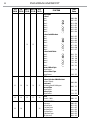
PANORAMAIPSPOT
18
STD EXT BAS-8 BAS-16 EXT2
FUNCTION
DMX
Value
28 Ch 29 Ch 19 Ch 21 Ch 36 Ch
11 13
ROTATING GOBO
Indexed
Open
Gobo 1
Gobo 2
Gobo 3
Gobo 4
Gobo 5
Gobo 6
Gobo 7
Indexed with Blackout
Open
Gobo 1
Gobo 2
Gobo 3
Gobo 4
Gobo 5
Gobo 6
Gobo 7
Indexed with Shake
Gobo 1 (from slow to fast)
Gobo 2 (from slow to fast)
Gobo 3 (from slow to fast)
Gobo 4 (from slow to fast)
Gobo 5 (from slow to fast)
Gobo 6 (from slow to fast)
Forward Wheel Spin
Stop to fastest
Reverse Wheel Spin
Stop to fastest
000 - 005
006- 011
012- 017
018 - 023
024 - 029
030 - 035
036 - 041
042 - 047
048 - 053
054 - 059
060 - 065
066 - 071
072 - 077
078 - 083
084 - 089
090 - 097
098 - 115
116 - 133
134- 151
152 - 169
170 - 187
188 - 205
224 - 239
240 - 255
17 18 23
GOBO ROTATION FUNCTION
Continuous
Forward Spin
Reverse Spin
Forward Animate Rotate
Forward Animate Rotate with Blackout
Reverse Animate Rotate
Reverse Animate Rotate with Blackout
TBD (not used)
000 - 015
016 - 031
032 - 047
048 - 063
064 - 079
080 - 095
096 - 111
112 - 255
18 19 24
GOBO ROTATION FUNCTION
Continuous
Positioning from 0-360 degrees
Forward & Reverse Spin
Stop to fastest
Forward & Reverse Animate Rotate
Stop to fastest
000 - 255
000- 255
000 - 255
La pagina sta caricando ...
La pagina sta caricando ...
La pagina sta caricando ...
La pagina sta caricando ...
La pagina sta caricando ...
La pagina sta caricando ...
La pagina sta caricando ...
La pagina sta caricando ...
La pagina sta caricando ...
La pagina sta caricando ...
La pagina sta caricando ...
La pagina sta caricando ...
La pagina sta caricando ...
La pagina sta caricando ...
La pagina sta caricando ...
La pagina sta caricando ...
La pagina sta caricando ...
La pagina sta caricando ...
La pagina sta caricando ...
La pagina sta caricando ...
La pagina sta caricando ...
La pagina sta caricando ...
La pagina sta caricando ...
La pagina sta caricando ...
La pagina sta caricando ...
La pagina sta caricando ...
La pagina sta caricando ...
La pagina sta caricando ...
La pagina sta caricando ...
La pagina sta caricando ...
La pagina sta caricando ...
La pagina sta caricando ...
La pagina sta caricando ...
La pagina sta caricando ...
La pagina sta caricando ...
La pagina sta caricando ...
La pagina sta caricando ...
La pagina sta caricando ...
La pagina sta caricando ...
La pagina sta caricando ...
La pagina sta caricando ...
La pagina sta caricando ...
La pagina sta caricando ...
La pagina sta caricando ...
La pagina sta caricando ...
La pagina sta caricando ...
La pagina sta caricando ...
La pagina sta caricando ...
-
 1
1
-
 2
2
-
 3
3
-
 4
4
-
 5
5
-
 6
6
-
 7
7
-
 8
8
-
 9
9
-
 10
10
-
 11
11
-
 12
12
-
 13
13
-
 14
14
-
 15
15
-
 16
16
-
 17
17
-
 18
18
-
 19
19
-
 20
20
-
 21
21
-
 22
22
-
 23
23
-
 24
24
-
 25
25
-
 26
26
-
 27
27
-
 28
28
-
 29
29
-
 30
30
-
 31
31
-
 32
32
-
 33
33
-
 34
34
-
 35
35
-
 36
36
-
 37
37
-
 38
38
-
 39
39
-
 40
40
-
 41
41
-
 42
42
-
 43
43
-
 44
44
-
 45
45
-
 46
46
-
 47
47
-
 48
48
-
 49
49
-
 50
50
-
 51
51
-
 52
52
-
 53
53
-
 54
54
-
 55
55
-
 56
56
-
 57
57
-
 58
58
-
 59
59
-
 60
60
-
 61
61
-
 62
62
-
 63
63
-
 64
64
-
 65
65
-
 66
66
-
 67
67
-
 68
68


ProLights PANORAMAIPSPOT Manuale utente
- Categoria
- Proiettori
- Tipo
- Manuale utente
in altre lingue
- English: ProLights PANORAMAIPSPOT User manual
Documenti correlati
-
ProLights STARK1000 Manuale utente
-
-
-
-
-
-
-
-
-
Altri documenti
-
CHAUVET DJ Gobozap 2x90w LED In-Air Gobo Sweeping Lighting Effect Guida utente
-
Clay Paky C61700 C61701 Manuale utente
-
PROEL PLML575E Manuale utente
-
Sagitter SG AQUFLEX7Z Manuale utente
-
-
-
CHAUVET DJ DMX-AN Guida utente
-
 COEF MASTERSHOW 512 Istruzioni per l'uso
