Pioneer AVH-X1500DVD Manuale del proprietario
- Categoria
- Microfoni
- Tipo
- Manuale del proprietario
Questo manuale è adatto anche per

Installation Manual
Manuel d’installation
Manuale d’installazione
Manual de instalación
Installationsanleitung
Installatiehandleiding
DVD RDS AV RECEIVER
AUTORADIO AV RDS LECTEUR DE DVD
SINTOLETTORE DVD RDS CON AV
RADIO AV RDS CON DVD
DVD-RDS-AV-EMPFÄNGER
DVD RDS AV-ONTVANGER
AVH-X5500BT
AVH-X3500DAB
AVH-X2500BT
AVH-X1500DVD
English NederlandsDeutschEspañolItalianoFrançais

WARNING
! To avoid the risk of accident and the potential vio-
lation of applicable laws, no viewing of front seat
video should ever occur while the vehicle is
being driven. Also, rear displays should not be in
a location where they are visibly distracting to
the driver.
! In some countries or states the viewing of images
on a display inside a vehicle even by persons
other than the driver may be illegal. Where such
regulations apply, they must be obeyed and this
unit’s DVD features should not be used.
CAUTION
! PIONEER does not recommend that you in-
stall or service your display unit yourself. In-
stalling or servicing the product may expose
you to risk of electric shock or other hazards.
Refer all installation and servicing of your
display unit to authorized Pioneer service
personnel.
! Do not drill a hole into the engine compart-
ment to connect the yellow cable of the dis-
play unit to the vehicle battery. Engine
vibration may eventually cause the insulation
to fail at the point where the wire passes
from the passenger compartment into the
engine compartment. Take extra care in se-
curing the wire at this point.
! Make sure that cables will not interfere with
moving parts of the vehicle, such as the shift
lever, parking brake or seat sliding mecha-
nism.
WARNING
! LIGHT GREEN LEAD AT POWER CONNEC-
TOR IS DESIGNED TO DETECT PARKED
STATUS AND MUST BE CONNECTED TO
THE POWER SUPPLY SIDE OF THE PARK-
ING BRAKE SWITCH. IMPROPER CON-
NECTION OR USE OF THIS LEAD MAY
VIOLATE APPLICABLE LAW AND MAY RE-
SULT IN SERIOUS INJURY OR DAMAGE.
Important
! This unit cannot be installed in a vehicle
without ACC (accessory) position on the igni-
tion switch.
O
N
S
T
A
R
T
O
F
F
ACC position No ACC position
! Use of this unit in conditions other than the
following could result in fire or malfunction.
— Vehicles with a 12-volt battery and negative
grounding.
— Speakers with 50 W (output value) and 4 W to
8 W (impedance value).
! To prevent a short-circuit, overheating or mal-
function, be sure to follow the directions
below.
— Disconnect the negative terminal of the bat-
tery before installation.
— Secure the wiring with cable clamps or adhe-
sive tape. Wrap adhesive tape around wiring
that comes into contact with metal parts to
protect the wiring.
— Place all cables away from moving parts,
such as the shift lever and seat rails.
— Place all cables away from hot places, such
as near the heater outlet.
— Do not connect the yellow cable to the battery
by passing it through the hole to the engine
compartment.
— Cover any disconnected cable connectors
with insulating tape.
— Do not shorten any cables.
— Never cut the insulation of the power cable of
this unit in order to share the power with
other devices. The current capacity of the
cable is limited.
— Use a fuse of the rating prescribed.
— Never wire the negative speaker cable directly
to ground.
— Never band together negative cables of multi-
ple speakers.
! When this unit is on, control signals are sent
through the blue/white cable. Connect this
cable to the system remote control of an ex-
ternal power amp or the vehicle’s auto-anten-
na relay control terminal (max. 300 mA
12 V DC). If the vehicle is equipped with a
glass antenna, connect it to the antenna
booster power supply terminal.
! Never connect the blue/white cable to the
power terminal of an external power amp.
Also, never connect it to the power terminal
of the auto antenna. Doing so may result in
battery drain or a malfunction.
! The black cable is ground. Ground cables for
this unit and other equipment (especially,
high-current products such as power amps)
must be wired separately. If they are not, an
accidental detachment may result in a fire or
malfunction.
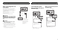
Connecting the units
2
Section
Connecting the units
En
01

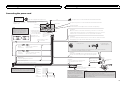
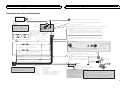
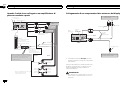
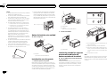
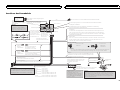
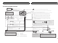
Connecting the power cord
Notes:
· Change the initial setting of this unit (refer to the Operation Manual).
The subwoofer output of this unit is monaural.
· When using a subwoofer of 70 W (2 Ω) , be sure to connect with Violet
and Violet/black leads of this unit. Do not connect anything to Green
and Green/black leads.
Connection method
1. Clamp the lead.
2. Clamp firmly with
needle-nosed pliers.
Note:
· The position of the parking brake switch depends on the vehicle model. For details,
consult the vehicle Owner’s Manual or dealer.
Yellow/black
If you use an equipment with Mute function, wire this lead to the Audio Mute lead on
that equipment. If not, keep the Audio Mute lead free of any connections.
Light green
Used to detect the ON/OFF status of the parking brake. This lead
must be connected to the power supply side of the parking brake
switch.
Blue/white
Connect to system control terminal of the
power amp (max. 300 mA 12 V DC).
Blue/white (6*)
Connect to auto-antenna relay control terminal
(max. 300 mA 12 V DC).
The pin position of the ISO
connector will differ depending on
the type of vehicle. Connect 5* and
6* when Pin 5 is an antenna control
type. In another type of vehicle,
never connect 5* and 6*.
Blue/white (5*)
Ground side
Power supply side
Parking brake
switch
ISO connector
Note:
In some vehicles, the ISO connector may be divided into
two. In this case, be sure to connect to both connectors.
Note:
Depending on the kind of vehicle,
the function of 2* and 4* may be
different. In this case, be sure to
connect 1* to 4* and 3* to 2*.
1*
3*
2*
4*
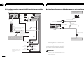
Yellow (2*)
Back-up
(or accessory)
Yellow (1*)
Connect to the constant 12 V
supply terminal.
Connect leads of the same
color to each other.
Red (4*)
Accessory
(or back-up)
Red (3*)
Connect to terminal controlled by
ignition switch (12 V DC).
Black (chassis ground)
Connect to a clean, paint-free metal location.
This product
Microphone (Function of AVH-X5500BT/AVH-X3500DAB/AVH-X2500BT)
Antenna input
Orange/white
Connect to lighting switch terminal.
Violet/white
Of the two lead wires connected to the back lamp, connect the one in which the
voltage changes when the gear shift is in the REVERSE (R) position. This connection
enables the unit to sense whether the car is moving forwards or backwards.
4 m
Fuse (10 A)
RGB input
Navigation system
(AVIC-F220 (sold
separately))
Please contact your dealer to
inquire about the connectable
navigation unit.
Wired remote input
Hard-wired remote control adapter can be connected (sold separately).
Insert the 26 pin cable in the direction
indicated in the figure.
26 pin cable (Supplied with navigation unit)
Microphone input (Function of AVH-X5500BT/AVH-X3500DAB/AVH-X2500BT)
AUX jack (3.5 ø)
Use a mini plug
cable to connect
with auxiliary
device.
Speaker leads
White: Front left
White/black: Front left
Gray: Front right
Gray/black: Front right
Green: Rear left or subwoofer
Green/black: Rear left or subwoofer
Violet: Rear right or subwoofer
Violet/black: Rear right or subwoofer
DAB antenna input
(AVH-X3500DAB only)
To receive DAB signals,
connect a DAB antenna
(AN-DAB1) sold
separately to the unit.
English
Connecting the units
3
Section
Connecting the units
En
01

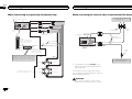
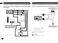
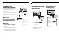
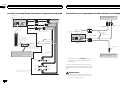
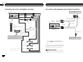
When connecting to separately sold power amp
Right
Subwoofer Subwoofer
This product
Blue/white (5*)
System remote control
The pin position of the ISO connector will differ
depending of the type of vehicle. Connect 5* and
6* when Pin 5 is an antenna control type. In
another type of vehicle, never connect 5* and 6*.
Blue/white (6*)
Connect to auto-antenna
relay control terminal
(max. 300 mA 12 V DC).
Perform these connections when
using the optional amplifier.
Front speaker Front speaker
Rear speaker Rear speaker
Left
Blue/white
Connect to system control
terminal of the power amp
(max. 300 mA 12 V DC).
Connect with RCA cables
(sold separately)
Subwoofer
output
Front output
Rear output
To front output
To rear output
To subwoofer
output
Power amp
(sold separately)
Power amp
(sold separately)
Power amp
(sold separately)
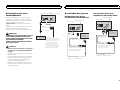
When connecting the external video component and the display
External video component
(sold separately)
Audio inputs
(R IN, L IN)
Display with RCA input
jacks (sold separately)
To video
input
To video
output
To audio outputs
T
his product
RCA cables
(sold separately)
Rear monitor output
(V OUT)
Video input (V IN)
! It is necessary to change AV Input in the
system menu when connecting the external
video component.
This product’s rear video output is for connec-
tion of a display to enable passengers in the rear
seats to watch the DVD, etc.
WARNING
! Never install a rear display in a location that is
visible to the driver while the vehicle is in motion.
Connecting the units
4
Section
Connecting the units
En
01

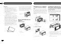
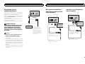
When connecting with a rear
view camera
When the shift lever is switched to REVERSE
(R), the display on this unit automatically
switches to the rear view image. You need to set
the Camera Polarity properly in the system
menu.
You can also switch the rear view image by
pressing the touch key.
For details, refer to operation manual.
WARNING
USE INPUT ONLY FOR REVERSE OR MIR-
ROR IMAGE REAR VIEW CAMERA. OTHER
USE MAY RESULT IN INJURY OR DAM-
AGE.
CAUTION
! You must use a camera which outputs
mirror reversed images.
! The screen image may appear reversed.
! The rear view camera function is to be used
as an aid to keep an eye on trailers, or while
backing up. Do not use for entertainment
purposes.
! Objects in the rear view may appear closer or
more distant than they actually are.
To video output
Rear view camera
(sold separately)
Rear view camera input (R.C IN)
Violet/white
Of the two lead wires
connected to the back lamp,
connect the one in which the
voltage changes when the
gear shift is in the REVERSE
(R) position. This connection
enables the unit to
sense whether the car is
moving forwards or
backwards.
This product
RCA cable
(sold separately)
Connecting the system
When connecting with optional
CD-IU201V cable
T
his product
Interface cable
(CD-IU201V) (sold separately)
AUX input
(AUX)
1.5 m
Dock connector
USB cable
(Supplied with this unit)
Connect to separately sold
USB device.
USB/iPod input
iPod with video
capabilities
(sold separately)
When connecting with optional
CD-IU201S cable
This product
1.5 m
Dock connector
USB cable
(Supplied with this unit)
Connect to separately sold
USB device.
USB/iPod input
iPod with video
capabilities
(sold separately)
RGB input
Interface cable
(CD-IU201S) (sold separately)
English
Connecting the units
5
Section
Connecting the units
En
01

Notes
! Check all connections and systems before
final installation.
! Do not use unauthorized parts as this may
cause malfunctions.
! Consult your dealer if installation requires
drilling of holes or other modifications to the
vehicle.
! Do not install this unit where:
— it may interfere with operation of the vehicle.
— it may cause injury to a passenger as a result
of a sudden stop.
! Do not install the display where it may (i) ob-
struct the driver’s vision, (ii) impair the per-
formance of any of the vehicle’s operating
systems or safety features, including air
bags, hazard lamp buttons or (iii) impair the
driver’s ability to safely operate the vehicle.
! The semiconductor laser will be damaged if
it overheats. Install this unit away from hot
places such as near the heater outlet.
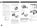
! Optimum performance is obtained when the
unit is installed at an angle of less than 30°.
! When installing, to ensure proper heat dis-
persal when using this unit, make sure you
leave ample space behind the rear panel and
wrap any loose cables so they are not block-
ing the vents.
5cmcm
Leave ample
space
5 cm
5 cm
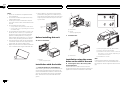
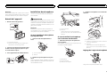
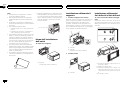
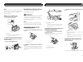
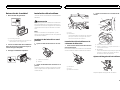
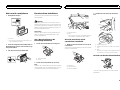
Before installing this unit
% Remove the holder.
1
1 Holder
(factory-supplied part)
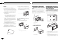
Installation with the holder
1 Install the holder into the dashboard.
After inserting the holder into the dashboard, se-
lect and bend the tabs appropriate to the thick-
ness of the dashboard material. (Install this unit
as firmly as possible using the top and bottom
tabs. To secure this unit, bend the tabs 90 de-
grees.)
1
2
1 Dashboard
2 Holder
(factory-supplied part)
2 Install this unit.
1
1 Dashboard
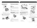
Installation using the screw
holes on the side of the unit
% Fastening the unit to the factory radio-
mounting bracket.
Position the unit so that its screw holes are
aligned with the screw holes of the bracket, and
tighten the screws at 3 locations on each side.
1
2
3
4
1 If the pawl gets in the way, bend it down.
2 Factory radio mounting bracket
3 Use either truss (5 mm × 8 mm) or flush sur-
face (5 mm × 9 mm) screws, depending on
the bracket screw holes.
4 Dashboard or console
Note
In some types of vehicles, discrepancy may
occur between the unit and the dashboard. If
this happens, use the supplied frame to fill the
gap.
Installation
6
Section
Installation
En
02

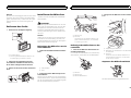
Removing the unit
1 Remove the trim ring.
1
1 Trim ring
! Releasing the front panel allows easier ac-
cess to the trim ring.
2 Insert the supplied extraction keys into
both sides of the unit until they click into
place.
3 Pull the unit out of the dashboard.
Installing the microphone
(Function of AVH-X5500BT/AVH-X3500DAB/AVH-
X2500BT)
CAUTION
It is extremely dangerous to allow the micro-
phone lead to become wound around the steer-
ing column or shift lever. Be sure to install the
unit in such a way that it will not obstruct driv-
ing.
Note
Install the microphone in a position and orienta-
tion that will enable it to pick up the voice of the
person operating the system.
When installing the microphone
on the sun visor
1 Fit the microphone lead into the groove.
1
2
1 Microphone lead
2 Groove
2 Install the microphone clip on the sun
visor.
With the sun visor up, install the microphone
clip. (Lowering the sun visor reduces the voice
recognition rate.)
1
2
1 Microphone clip
2 Clamp
Use separately sold clamps to secure the
lead where necessary inside the vehicle.
When installing the microphone
on the steering column
1 Detach the microphone base from the mi-
crophone clip.
To detach the microphone base from the micro-
phone clip, slide the microphone base.
1
2
3
1 Microphone
2 Microphone clip
3 Microphone base
2 Install the microphone on the steering
column.
1
2
3
1 Double-sided tape
2 Install the microphone on the rear side of the
steering column.
3 Clamp
Use separately sold clamps to secure the
lead where necessary inside the vehicle.
Adjusting the microphone angle
The microphone angle can be adjusted.
English
Installation
7
Section
Installation
En
02

ATTENTION
! Pour éviter le risque d’accident et une violation
potentielle des lois applicables, l’écran du siège
avant ne doit en aucun cas être regardé pendant
la conduite du véhicule. En outre, les écrans ar-
rière ne doivent pas être placés dans un endroit
où ils constituent visiblement une distraction
pour le conducteur.
! Dans certains états ou pays, il peut être illégal
même pour des personnes autres que le conduc-
teur de regarder des images sur un écran à l’inté-
rieur d’un véhicule. Quand cette réglementation
est applicable, elle doit être respectée, et les
fonctions DVD de cet appareil ne doivent pas
être utilisées.
PRÉCAUTION
! PIONEER ne recommande pas que vous in-
stalliez ou entreteniez votre écran vous
même. L’installation ou l’entretien du produit
peut vous exposer à des risques d’électrocu-
tion ou à d’autres dangers. Adressez-vous à
du personnel d’entretien agréé par Pioneer
pour l’installation et l’entretien de votre
écran.
! Ne percez pas de trous vers le compartiment
moteur pour connecter le câble jaune de l’é-
cran à la batterie du véhicule. Les vibrations
du moteur peuvent provoquer un défaut d’is-
olement à l’endroit où le fil passe du compar-
timent passager au compartiment moteur.
Apportez une attention particulière à la fixa-
tion du fil à cet endroit.
! Assurez-vous que les câbles n’interfèrent pas
avec des parties mobiles du véhicule, telles
que le levier de vitesse, le frein de parking ou
le mécanisme de glissement des sièges.
ATTENTION
! LE FIL VERT CLAIR DU CONNECTEUR D’A-
LIMENTATION EST PRÉVU POUR DÉTEC-
TER L’ÉTAT STATIONNÉ ET DOIT ÊTRE
CONNECTÉ À L’ALIMENTATION DU
COMMUTATEUR DU FREIN DE PARKING.
UNE MAUVAISE CONNEXION OU UNE UTI-
LISATION INCORRECTE DU FIL PEUT VIO-
LER LA LOI APPLICABLE ET SE TRADUIRE
PAR DES DOMMAGES CORPORELS OU
MATÉRIELS GRAVES.
Important
! Cet appareil ne peut pas être installé dans
un véhicule ne disposant pas d’une position
ACC (accessoire) sur le contact d’allumage.
O
N
S
T
A
R
T
O
F
F
Avec position ACC Sans position ACC
! L’utilisation de cet appareil dans des condi-
tions autres que les conditions suivantes
pourrait provoquer un incendie ou un mau-
vais fonctionnement.
— Véhicules avec une batterie 12 volts et mise à
la masse du négatif.
— Haut-parleurs avec une puissance de sortie
de 50 W et une impédance de 4 W à8W.
! Pour éviter un court-circuit, une surchauffe
ou un dysfonctionnement, assurez-vous de
respecter les instructions suivantes.
— Déconnectez la borne négative de la batterie
avant l’installation.
— Fixez le câblage avec des serre-fils ou de la
bande adhésive. Pour protéger le câblage, en-
roulez dans du ruban adhésif les parties du
câblage en contact avec des pièces en métal.
— Placez les câbles à l’écart de toutes les par-
ties mobiles, telles que le levier de vitesse et
les rails des sièges.
— Placez les câbles à l’écart de tous les endroits
chauds, par exemple les sorties de chauf-
fage.
— Ne reliez pas le câble jaune à la batterie à tra-
vers le trou dans le compartiment moteur.
— Recouvrez tous les connecteurs de câbles qui
ne sont pas connectés avec du ruban adhésif
isolant.
— Ne raccourcissez pas les câbles.
— Ne coupez jamais l’isolation du câble d’ali-
mentation de cet appareil pour partager l’ali-
mentation avec d’autres appareils. La
capacité en courant du câble est limitée.
— Utilisez un fusible correspondant aux caracté-
ristiques spécifiées.
— Ne câblez jamais le câble négatif du haut-par-
leur directement à la masse.
— Ne réunissez jamais ensemble les câbles né-
gatifs de plusieurs haut-parleurs.
! Lorsque cet appareil est sous tension, les si-
gnaux de commande sont transmis via le
câble bleu/blanc. Connectez ce câble à la té-
lécommande du système d’un amplificateur
de puissance externe ou à la borne de
commande du relais de l’antenne motorisée
du véhicule (max. 300 mA 12 V CC). Si le véhi-
cule est équipé d’une antenne intégrée à la
lunette arrière, connectez-le à la borne d’ali-
mentation de l’amplificateur d’antenne.
! Ne reliez jamais le câble bleu/blanc à la
borne d’alimentation d’un amplificateur de
puissance externe. De même, ne le reliez pas
à la borne d’alimentation de l’antenne moto-
risée. Dans le cas contraire, il peut en résul-
ter un déchargement de la batterie ou un
dysfonctionnement.
! Le câble noir est la masse. Les câbles de
terre de cet appareil et d’autres produits (par-
ticulièrement les produits avec des courants
élevés tels que l’amplificateur de puissance)
doivent être câblés séparément. Dans le cas
contraire, ils peuvent se détacher accidentel-
lement et provoquer un incendie ou un dys-
fonctionnement.
Connexion des appareils
8
Section
Connexion des appareils
Fr
01

Connexion du cordon d’alimentation
Remarques:
· Change le réglage initial de cet appareil (reportez-vous aux mode
d’emploi). La sortie de caisson de grave de cet appareil est
monophonique.
· Lors de l’utilisation d’un haut-parleur d’extrêmes graves de 70 W (2 Ω),
assurez-vous de le raccorder aux conducteurs violet et violet/noir de
cet appareil. Ne raccordez rien aux conducteurs vert et vert/noir.
Méthode de connexion
1. Serrez le conducteur
2. Serrez fermement avec
une pince à mâchoires
pointues.
Remarque:
· La position du contacteur de frein à main dépend du modèle de véhicule. Pour les détails,
consultez le manuel de l’utilisateur du véhicule ou un concessionnaire.
Jaune/noir
Si vous utilisez un équipement avec la fonction Coupure du son, câblez ce fil au fil
Coupure Audio de cet équipement. Sinon, ne connectez rien au fil Coupure Audio.
Vert clair
Utilisé pour détecter l’état ON/OFF du frein à main.
Ce conducteur doit être raccordé sur l’alimentation du contacteur
de frein à main.
Bleu/blanc
Connectez à la prise de commande du système
de l’amplificateur de puissance (max. 300 mA
12 V DC).
Bleu/blanc (6*)
Connectez à la prise du contrôle de relais de
l’antenne automatique (max. 300 mA, 12 V DC).
La position des broches du
connecteur ISO est différente selon
le type de véhicule. Connectez 5* et
6* lorsque la broche 5 est de type
commande de l’antenne. Dans un
type différent de véhicule, ne
connectez jamais 5* et 6*.
Bleu/blanc (5*)
Côté mise à terre
Côté alimentation
Contacteur de
frein à main
Câbles d’enceinte
Blanc: Avant gauche
Blanc/noir: Avant gauche
Gris: Avant droit
Gris/noir: Avant droit
Vert: Arrière gauche ou caisson de grave
Vert/noir: Arrière gauche ou caisson de grave
Violet: Arrière droit ou caisson de grave
Violet/noir: Arrière droit ou caisson de grave
Connecteur ISO
Remarque:
En fonction du type de véhicule, la
fonction de 2* et de 4* peut
différer. Sans ce cas, assurez-vous
de connecter 1* à 4* et 3* à 2*.
1*
3*
2*
4*
Jaune (2*)
Secours
(ou accessoire)
Jaune (1*)
Connectez à une prise
d’alimentation constante 12 V.
Connectez les câbles de la même
couleur les uns aux autres.
Rouge (4*)
Accessoire
(ou secours)
Rouge (3*)
Connectez à une prise commandée
par le commutateur d’allumage
(12 V DC).
Noire (masse au châssis)
Connectez à une section métallique propre et sans peinture.
Microphone (Fonction de l’AVH-X5500BT/AVH-X3500DAB/AVH-X2500BT)
Entrée d’antenne
Orange/blanc
Connectez à la prise du commutateur d’éclairage.
Violet/blanc
Des deux conducteurs connectés au feu de recul, connectez celuipour lequel la
tension change quand le sélecteur de vitesse est sur la position REVERSE (R). Cette
connexion permet à l’appareil de détecter si la voiture se déplace vers l’avant ou vers
l’arrière.
4 m
Fusible (10 A)
Entrée RGB
Unité de navigation
(AVIC-F220 (vendue
séparément)).
Veuillez contacter votre revendeur
pour en savoir plus sur les unités
de navigation pouvant être
raccordées.
Entrée pour télécommande câblée
Un adaptateur de télécommande câblée peut être connecté à cette prise (vendu séparément).
Insérez le câble 26 broches dans
la direction indiquée sur la figure.
Câble 26 broches (fourni avec l’unité de
navigation)
Entrée microphone (Fonction de l’AVH-X5500BT/AVH-X3500DAB/AVH-X2500BT)
Remarque:
Dans certains véhicule, le connecteur ISO peut être
divisé en deux. Dans ce cas, assurez-vous de faire la
connexion aux deux connecteurs.
Cet appareil
Prise AUX (3,5 ø)
Utilisez un câble a
fiches mini pour
raccorder un
appareil auxiliaire.
Entrée de l'antenne DAB
(AVH-X3500DAB uniquement)
pour recevoir des signaux
DAB, branchez une antenne
DAB (AN-DAB1), vendue
séparément, sur l'unité.
Français
Connexion des appareils
9
Section
Connexion des appareils
Fr
01

Lors de la connexion à un amplificateur de puissance vendu
séparément
Bleu/blanc
Connectez à la prise de commande
du système de l’amplificateur de
puissance (max. 300 mA 12 V DC).
Bleu/blanc (6*)
Connectez à la prise du
contrôle de relais de
l’antenne automatique
(max. 300 mA, 12 V DC).
La position des broches du connecteur ISO est
différente selon le type de véhicule. Connectez 5*
et 6* lorsque la broche 5 est de type commande
de l’antenne. Dans un type différent
de véhicule,
ne connectez jamais 5* et 6*.
Bleu/blanc (5*)
Connectez aux câbles cinch
(RCA) (vendus séparément)
Enceinte
avant
Enceinte
avant
Réalisez ces connexions lors de
l’utilisation de l’amplificateur en
option.
Télécommande du système
Enceinte
arrière
Enceinte
arrière
Gauche Droit
Amplificateur de
puissance (vendu
séparément)
Amplificateur de
puissance (vendu
séparément)
Amplificateur de
puissance (vendu
séparément)
Caisson de
grave
Caisson de
grave
À la sortie avant
À la sortie arrière
À la sortie du
caisson de grave
Cet appareil
Sortie arrière
Sortie avant
Sortie du caisson
de grave
Lors de la connexion du composant vidéo externe et de l’écran
Appareil vidéo externe (vendu
séparément)
Entrée audio
(R IN, L IN)
Écran muni de prises d’entrée
Cinch (RCA) (vendu séparément)
Vers l’entrée vidéo
À la sortie vidéo
Aux sorties audio
Cet appareil
Câbles à fiches Cinch
(RCA)
(vendu séparément)
Sortie du moniteur arrière
(V OUT)
Entrée vidéo (V IN)
! Il est nécessaire de remplacer AV Input
dans le menu système lors de la connexion
du composant vidéo externe.
La sortie vidéo arrière de cet appareil est prévue
pour connecter un écran afin de permettre aux
passagers des sièges arrières de regarder des
DVD, etc.
ATTENTION
! N’installez jamais d’écran arrière dans un endroit
où il est visible du conducteur lorsque le véhicule
circule.
Connexion des appareils
10
Section
Connexion des appareils
Fr
01

Lors de la connexion à une
caméra de vue arrière
Quand le levier de vitesse est en position MAR-
CHE ARRIÈRE (R), l’affichage bascule automati-
quement sur l’image de vue arrière. Vous devez
régler Camera Polarity correctement dans le
menu système.
Vous pouvez également basculer sur l’image de
vue arrière en appuyant sur la touche tactile.
Pour plus de détails, reportez-vous au mode
d’emploi.
ATTENTION
UTILISEZ CETTE ENTRÉE SEULEMENT
POUR UNE CAMÉRA DE VUE ARRIÈRE
DONNANT UNE IMAGE INVERSÉE OU MI-
ROIR. TOUTE AUTRE UTILISATION PEUT
PROVOQUER DES BLESSURES OU DES
DOMMAGES.
PRÉCAUTION
! Vous devez utiliser une caméra qui gé-
nère des images inversées (images mi-
roir).
! L’image sur l’écran peut apparaître inversée.
! La fonction caméra de vue arrière doit être
utilisée comme une aide pour avoir un œil
sur une remorque ou lors d’une marche ar-
rière. Ne l’utilisez pas à des fins de divertisse-
ment.
! Les objets sur la vue arrière peuvent apparaî-
tre plus près ou plus loin qu’ils ne le sont en
réalité.
À la sortie vidéo
Caméra de recul
(vendu séparément)
Entrée de la caméra de recul
(R.C IN)
Violet/blanc
Des deux conducteurs
connectés au feu de recul,
connectez celui pour lequel la
tension change quand le
sélecteur de vitesse est sur la
position REVERSE (R). Cette
connexion permet à l’appareil
de détecter si la voiture se
déplace vers l’avant ou vers
l’arrière.
Cet appareil
Câble à fiches
Cinch (RCA)
(vendu
séparément)
Connexion du système
Lors de la connexion avec le
câble CD-IU201V en option
Cet appareil
Câble d’interface
(CD-IU201V) (vendu séparément)
Entrée AUX
(AUX)
1,5 m
Connecteur Dock
Câble USB
(Fourni avec cet appareil)
Connectez à un périphérique
USB vendu séparément.
Entrée USB/iPod
iPod avec
capacité vidéo
(vendu séparément)
Lors de la connexion avec le
câble CD-IU201S en option
Cet appareil
1,5 m
Connecteur Dock
Câble USB
(Fourni avec cet appareil)
Connectez à un périphérique
USB vendu séparément.
Entrée USB/iPod
iPod avec
capacité vidéo
(vendu séparément)
Entrée RGB
Câble d’interface
(CD-IU201S) (vendu séparément)
Français
Connexion des appareils
11
Section
Connexion des appareils
Fr
01

Remarques
! Vérifiez toutes les connexions et tous les sys-
tèmes avant l’installation finale.
! N’utilisez pas de pièces non autorisées car il
peut en résulter des dysfonctionnements.
! Consultez votre revendeur si l’installation né-
cessite le perçage de trous ou d’autres modi-
fications du véhicule.
! N’installez pas cet appareil là où :
— il peut interférer avec l’utilisation du véhicule.
— il peut blesser un passager en cas d’arrêt
soudain du véhicule.
! N’installez pas l’écran là où il peut (i) gêner
la vision du conducteur, (ii) dégrader le fonc-
tionnement de systèmes d’utilisation ou les
dispositifs de sécurité du véhicule, incluant
les airbags, les commandes du signal de dé-
tresse, ou (iii) dégrader la capacité du
conducteur à utiliser le véhicule en sécurité.
! Le laser à semi-conducteur sera endommagé
s’il devient trop chaud. Installez cet appareil
àl’écart de tous les endroits chauds, par
exemple les sorties de chauffage.
! Des performances optimales sont obtenues
quand l’appareil est installé à un angle infé-
rieur à 30°.
! Lors de l’installation, pour assurer une dis-
persion correcte de la chaleur quand cet ap-
pareil est utilisé, assurez-vous de laisser un
espace important derrière la face arrière et
enroulez les câbles volants de façon qu’ils ne
bloquent pas les orifices d’aération.
5cmcm
Laissez suffisamment
d’espace
5 cm
5 cm
Avant l’installation de cet
appareil
% Retirez le support.
1
1 Support
(pièce fournie)
Installation avec le support
1 Installez le support dans le tableau de
bord.
Une fois le support installé dans le tableau de
bord, sélectionnez et courber les pattes en fonc-
tion de l’épaisseur du tableau de bord. (Fixez cet
appareil aussi fermement que possible à l’aide
des pattes supérieures et inférieures. Afin de
fixer fermement l’appareil, courbez les pattes de
90 degrés.)
1
2
1 Tableau de bord
2 Support
(pièce fournie)
2 Installez cet appareil.
1
1 Tableau de bord
Installation à l’aide des trous
de vis sur les côtés de l’appareil
% Fixation de l’appareil sur le support de
montage radio d’usine.
Positionnez l’appareil de sorte que les trous des
vis soient alignés avec les trous des vis sur le
support, puis serrez les vis aux 3 emplacements
de chaque côté de l’appareil.
1
2
3
4
1 Courbez la languette vers le bas si elle gêne.
2 Support de montage radio d’usine
3 Utilisez des vis à tête bombée (5 mm × 8mm)
ou des vis en affleurement (5 mm × 9 mm),
selon la forme des trous de vis dans le sup-
port.
4 Tableau de bord ou console
Installation
12
Section
Installation
Fr
02

Remarque
Dans certains véhicules, il peut y avoir un écart
entre l’appareil et tableau de bord. Dans ce cas,
utilisez le cadre fourni pour combler l’espace.
Retrait de l’appareil
1 Retirez l’anneau de garniture.
1
1 Anneau de garniture
! Retirer la face avant permet d’accéder plus
facilement à l’anneau de garniture.
2 Insérez les clés d’extraction fournies dans
les deux côtés de l’appareil jusqu’àcequ’el-
les s’enclenchent en place.
3 Tirez l’appareil hors du tableau de bord.
Installation du microphone
(Fonction de AVH-X5500BT/AVH-X3500DAB/
AVH-X2500BT)
PRÉCAUTION
Il est extrêmement dangereux de laisser le fil du
microphone s’enrouler autour de la colonne de
direction ou du levier de vitesse. Assurez-vous
d’installer cet appareil de telle manière qu’il ne
gêne pas la conduite.
Remarque
Installez le microphone dans une position et
une orientation qui lui permette de capter la voix
de la personne qui utilise le système.
Si vous installez le microphone
sur le pare-soleil
1 Insérez le fil du microphone dans la
fente.
1
2
1 Fil du microphone
2 Rainure
2 Installez le clip microphone sur le pare-
soleil.
Avec le pare-soleil relevé, installez le clip micro-
phone. (Abaisser le pare-soleil réduit le taux de
reconnaissance vocale.)
1
2
1 Clip microphone
2 Serre-fils
Utilisez des serre-fils vendus séparément
pour fixer le fil là où c’est nécessaire dans le
véhicule.
Si vous installez le microphone
sur la colonne de direction
1 Détachez la base pour microphone du
clip microphone.
Pour détacher la base pour microphone du clip
microphone, faites-la glisser.
1
2
3
1 Microphone
2 Clip microphone
3 Base pour microphone
2 Installez le microphone sur la colonne de
direction.
1
2
3
1 Bande double face
2 Installez le microphone sur la face arrière de
la colonne de direction.
3 Serre-fils
Utilisez des serre-fils vendus séparément
pour fixer le fil là où c’est nécessaire dans le
véhicule.
Réglage de l’angle du microphone
L’angle du microphone peut être réglé.
Français
Installation
13
Section
Installation
Fr
02

AVVERTENZA
! Per evitare il rischio di incidenti e la potenziale
violazione delle normative in vigore, la visione dei
video dal sedile anteriore è vietata mentre il vei-
colo è in movimento. Inoltre, i display posteriori
non devono trovarsi in posizioni che possano rap-
presentare una distrazione visiva per il condu-
cente.
! In alcuni Stati o Paesi la visione di immagini su
un display installato all’interno di un veicolo,
anche da parte di persone diverse dal conducen-
te, potrebbe essere illegale. Se sono in vigore
norme di questo tipo, è necessario osservarle
scrupolosamente e le caratteristiche DVD di que-
sta unità non devono essere utilizzate.
ATTENZIONE
! PIONEER non raccomanda di installare o ef-
fettuare interventi di manutenzione sull’unità
display da soli. L’installazione o la manuten-
zione del prodotto può esporre al rischio di
scosse elettriche o altri pericoli. Per tutti gli
interventi di installazione e manutenzione
dell’unità display rivolgersi a personale tecni-
co autorizzato Pioneer.
! Non trapanare un foro nel comparto motore
per collegare il cavo giallo dell’unità display
alla batteria del veicolo. Le vibrazioni del mo-
tore possono a lungo andare danneggiare l’i-
solante nel punto dove il cavo passa
dall’abitacolo al comparto motore. Fare parti-
colare attenzione quando si fissa il cavo in
questo punto.
! Assicurarsi che i cavi non interferiscano con
le parti mobili del veicolo, come la leva del
cambio, il freno a mano o il meccanismo di
scorrimento dei sedili.
AVVERTENZA
! IL FILO DI COLORE VERDE CHIARO SUL
CONNETTORE DI ALIMENTAZIONE È PRO-
GETTATO PER RILEVARE LA CONDIZIONE
DI STAZIONAMENTO DEL VEICOLO E
DEVE ESSERE COLLEGATO AL LATO DI
ALIMENTAZIONE DELL’INTERRUTTORE
DEL FRENO DI STAZIONAMENTO. IL COL-
LEGAMENTO O L’USO NON CORRETTO DI
QUESTO FILO POTREBBE RAPPRESENTA-
RE UNA VIOLAZIONE DELLA NORMATIVA
APPLICABILE E PROVOCARE DANNI O LE-
SIONI GRAVI.
Importante
! Non è possibile installare questa unità in un
veicolo che non dispone della posizione ACC
(accessoria) per l’interruttore della chiave di
avviamento.
O
N
S
T
A
R
T
O
F
F
Con posizione ACC Senza posizione ACC
! Se questa unità viene utilizzata in condizione
diverse dalle seguenti, potrebbero verificarsi
incendi o malfunzionamenti.
— Veicoli dotati di batteria da 12 volt e messa a
terra negativa.
— Altoparlanti con uscita nominale da 50 W e
impedenza nominale compresa tra 4 W e8W.
! Per evitare rischi di cortocircuito, surriscalda-
mento o malfunzionamento, accertarsi di se-
guire le indicazioni riportate di seguito.
— Prima dell’installazione, scollegare il morset-
to negativo della batteria.
— Assicurare i cavi con morsetti per cavi o na-
stro adesivo. Per proteggere i cavi, avvolgere
nastro adesivo attorno agli stessi nei punti in
cui entrano in contatto con parti metalliche.
— Posizionare tutti i cavi in modo che non pos-
sano entrare in contatto con componenti mo-
bili, come la leva del cambio e i binari dei
sedili.
— Non posizionare i cavi in luoghi soggetti a
surriscaldamento, come le bocchette dell’im-
pianto di riscaldamento.
— Non collegare il cavo giallo alla batteria fa-
cendolo passare attraverso fori nel vano mo-
tore.
— Rivestire tutti i connettori scollegati con na-
stro isolante.
— Non accorciare i cavi.
— Non condividere mai l’alimentazione con altri
dispositivi tagliando l’isolante del cavo di ali-
mentazione dell’unità. La capacità di carico
di corrente del cavo è limitata.
— Utilizzare esclusivamente un fusibile con la
portata prescritta.
— Non collegare mai direttamente a terra il
cavo negativo dell’altoparlante.
— Non legare mai assieme cavi negativi di più
altoparlanti.
! Quando questa unità è accesa, i segnali di
controllo vengono trasmessi dal cavo blu/
bianco. Collegarlo al telecomando del siste-
ma di amplificazione di potenza o al termina-
le di controllo del relè dell’antenna
automatica del veicolo (max. 300 mA
12 V CC). Se il veicolo è dotato di un’antenna
a vetro, collegarla al terminale di alimentazio-
ne di potenza dell’antenna.
! Non collegare mai il cavo blu/bianco al ter-
minale di alimentazione dell’amplificatore di
potenza esterno. Inoltre, non collegarlo mai
al terminale di alimentazione dell’antenna
automatica. In caso contrario, la batteria po-
trebbe scaricarsi o potrebbero verificarsi mal-
funzionamenti.
! Il cavo nero è la messa a terra. I cavi di
messa a terra di questa unità e di altre appa-
recchiature (soprattutto per i prodotti ad alta
tensione, quali amplificatori di potenza) de-
vono essere collegati separatamente. In caso
contrario, se scollegati accidentalmente, po-
trebbero provocare incendi o malfunziona-
menti.
Collegamento delle unità
14
Sezione
Collegamento delle unità
It
01

Collegamento del cavo di alimentazione
Note:
· Cambiare l’impostazione iniziale di questa unità (far riferimento al
manuale d’istruzioni per l’uso). L’uscita subwoofer di questa unità è di
tipo mono.
· In caso d’installazione di un subwoofer da 70 W (2 Ω) è necessario
collegarlo con i cavi viola e viola/nero dell’unità. Ai cavi verde e
verde/nero non deve essere collegato alcunché.
Metodo di collegamento
1. Fissare il cavo.
2. Fissare saldamente
con pinze a punta.
Nota:
· La posizione dell’interruttore freno a mano dipende dal modello di veicolo. Per dettagli
consultare il manuale del veicolo o il concessionario.
Giallo/nero
Se si utilizza un apparecchio dotato di funzione di silenziamento, collegare questo
cavo al cavo di silenziamento audio di tale apparecchio. In caso contrario, non
collegare il cavo di silenziamento audio.
Luce verde
Usato per individuare lo stato attivato (ON)/disattivato (OFF) del
freno a mano. Questo cavo deve essere collegato al lato
alimentazione dell’interruttore freno a mano.
Blu/bianco
Da collegare al terminale di controllo di
sistema dell’amplificatore di potenza (massimo
300 mA 12 V DC).
Blu/bianco (6*)
Da collegare al terminale di controllo del relé
dell’antenna automatica (massimo 300 mA 12 V DC).
La posizione dei pin del connettore
ISO sarà diversa a seconda del tipo
di veicolo. Collegare 5* e 6* quando
il Pin 5 è del tipo controllo antenna.
In un altro tipo di veicolo, non
collegare mai 5* e 6*.
Blu/bianco (5*)
Lato massa
Lato alimentazione
Interruttore
freno a mano
Cavi altoparlanti
Bianco: Anteriore sinistro
Bianco/nero: Anteriore sinistro
Grigio: Anteriore destro
Grigio/nero: Anteriore destro
Verde: Posteriore sinistro o subwoofer
Verde/nero: Posteriore sinistro o subwoofer
Viola: Posteriore destro o subwoofer
Viola/nero: Posteriore destro o subwoofer
Nota:
In alcuni veicoli il connettore ISO potrebbe essere
separato in due. In tal caso è necessario collegare
entrambi.
Nota:
In funzione del tipo di veicolo le
funzione di 2* e di 4* potrebbe
differire. In tal caso collegare 1* a
4* e 3* a 2*.
1*
3*
2*
4*
Giallo (2*)
Retromarcia
(o accessorio)
Giallo (1*)
Da collegare al terminale
costantemente alimentato a 12 V.
Collegare fra loro i cavi di
uguale colore.
Rosso (4*)
Accessorio
(o retromarcia)
Rosso (3*)
Da collegare al terminale
controllato dalla chiavetta di
accensione (12 V DC).
Nero (messa a terra sulla carrozzeria)
Da collegare in un punto metallico pulito e non verniciato.
Microfono (funzione di AVH-X5500BT/AVH-X3500DAB/AVH-X2500BT)
Ingresso antenna
Arancione/bianco
Collegare al terminale dell’interruttore d’illuminazione.
Violetto/bianco
Dei due fili isolati collegati alla spia posteriore, collegare quello nel quale cambia il
voltaggio quando la leva del cambio è in posizione di REVERSE (R). Questo
collegamento consente all’unità di rilevare se l’automobile si sta muovendo in avanti
o all’indietro.
4 m
Fusibile (10 A)
Ingresso RGB
Unità di navigazione
(AVIC-F220 (in
vendita a parte)).
Per informazioni sugli apparecchi
di navigazione collegabili si prega
di rivolgersi al proprio rivenditore.
Ingresso per telecomando a filo
Qui si collega mediante cavo l’adattatore per telecomando (venduto a parte).
Collegare il cavo con spine da 26
contatti orientandolo come mostrato
in figura.
Cavo con spine da 26 contatti (in dotazione
all’unità di navigazione)
Ingresso microfono (funzione di AVH-X5500BT/AVH-X3500DAB/AVH-X2500BT)
Connettore ISO
Questo apparecchio
Presa AUX (3,5 ø)
Collegare l’apparecchio
ausiliario con un cavo
provvisto di spinotto
mini.
Ingresso antenna DAB
(solo AVH-X3500DAB)
Per ricevere i segnali DAB,
collegare all’unità un’antenna
DAB (AN-DAB1), venduta
separatamente.
Italiano
Collegamento delle unità
15
Sezione
Collegamento delle unità
It
01

Quando l’unità viene collegata a un amplificatore di
potenza venduto a parte
Blu/bianco
Da collegare al terminale di
controllo di sistema
dell’amplificatore di potenza
(massimo 300 mA 12 V DC).
Blu/bianco (6*)
Da collegare al terminale di
controllo del relé
dell’antenna automatica
(massimo 300 mA 12 V DC).
La posizione dei pin del connettore ISO sarà
diversa a seconda del tipo di veicolo. Collegare
5* e 6* quando il Pin 5 è del tipo controllo
antenna. In un altro tipo di veicolo, non
collegare mai 5* e 6*.
Blu/bianco (5*)
Da collegare ai cavi RCA
(venduti a parte)
Diffusore
anteriore
Diffusore
anteriore
Questi collegamenti devono essere
eseguiti quando s’impiega
l’amplificatore opzionale.
Telecomando del sistema
Diffusore
posteriore
Diffusore
posteriore
Sinistra Destra
Amplificatore di
potenza
(venduto a parte)
Amplificatore di
potenza
(venduto a parte)
Amplificatore di
potenza
(venduto a parte)
Subwoofer Subwoofer
All’uscita
posteriore
All’uscita
anteriore
All’uscita per
subwoofer
Questo apparecchio
Uscita posteriore
Uscita anteriore
Uscita per
subwoofer
Collegamento di un componente video esterno e del display
Componente video esterno
(venduto a parte)
Ingresso
audio
(R IN, L IN)
Schermo con prese di ingresso di
tipo RCA (venduto a parte)
All’ingresso video
All’uscita video
Alle uscite audio
Questo
apparecchio
Cavi RCA
(venduti
separatamente)
Uscita per monitor posteriore
(V OUT)
Ingresso video (V IN)
! È necessario cambiare AV Input nel menu
di sistema quando si collega un componente
video esterno.
L’uscita video posteriore di questo prodotto è de-
stinata al collegamento di un display che con-
sente ai passeggeri dei sedili posteriori la
visione dei DVD, ecc.
AVVERTENZA
! Non installare mai il display posteriore in una po-
sizione visibile al guidatore mentre il veicolo è in
movimento.
Collegamento delle unità
16
Sezione
Collegamento delle unità
It
01

Collegamento a una
telecamera per retromarcia
Quando viene inserita la RETROMARCIA (R), il
display passa automaticamente all’immagine
della telecamera per retromarcia. È necessario
impostare Camera Polarity correttamente nel
menu di sistema.
È inoltre possibile cambiare l’immagine della te-
lecamera per retromarcia toccando il tasto sul
touch panel.
Per ulteriori dettagli, vedere il manuale d’istru-
zioni.
AVVERTENZA
UTILIZZARE IL SEGNALE IN INGRESSO
ESCLUSIVAMENTE PER IMMAGINI IN-
VERTITE O SPECULA RI TRASMESSE
DALLA TELECAMERA PER RETROMAR-
CIA. USI DIVERSI POTREBBERO PROVO-
CARE LESIONI O DANNI.
ATTENZIONE
! È necessario utilizzare una telecamera
che trasmette immagini speculari.
! Le immagini su schermo potrebbero risultare
invertite.
! La funzione di telecamera per retromarcia
deve essere utilizzata solo come ausilio per
controllare il rimorchio o per la retromarcia.
Non utilizzarla a scopo di intrattenimento.
! Gli oggetti ripresi dalla telecamera per retro-
marcia possono apparire più vicini o distanti
di quanto non siano in realtà.
All’uscita video
Ingresso alla videocamera di
retromarcia (R.C IN)
Violetto/bianco
Dei due fili isolati collegati alla
spia posteriore, collegare
quello nel quale cambia il
voltaggio quando la leva del
cambio è in posizione di
REVERSE (R). Questo
collegamento consente
all’unità di rilevare se
l’automobile si sta muovendo
in avanti o all’indietro.
Questo apparecchio
Cavo RCA
(venduto a parte)
Videocamera di
retromarcia
(venduto a parte)
Collegamento del sistema
Collegamento con il cavo
opzionale CD-IU201V
Questo apparecchio
Cavo d’interfaccia
(CD-IU201V) (venduto a parte)
Ingresso AUX
(AUX)
1,5 m
Connettore Dock
Cavo USB
(fornito in dotazione a questa unità)
Collegare a un’unità USB da
acquistare a parte.
Ingresso USB/iPod
iPod con
capacità video
(acquistabile
separatamente)
Collegamento con il cavo
opzionale CD-IU201S
Questo apparecchio
1,5 m
Connettore Dock
Cavo USB
(fornito in dotazione a questa unità)
Collegare a un’unità USB da
acquistare a parte.
Ingresso USB/iPod
iPod con
capacità video
(acquistabile
separatamente)
Ingresso RGB
Cavo d’interfaccia
(CD-IU201S) (venduto a parte)
Italiano
Collegamento delle unità
17
Sezione
Collegamento delle unità
It
01

Note
! Controllare tutti i collegamenti e i sistemi
prima dell’installazione finale.
! Non utilizzare componenti non approvati,
poiché potrebbero provocare malfunziona-
menti.
! Consultare il rivenditore se l’installazione ri-
chiede la trapanatura di fori o altre modifiche
del veicolo.
! Non installare questa unità se:
— potrebbe interferire con il funzionamento del
veicolo.
— potrebbe procurare lesioni al passeggero in
caso di arresto improvviso del veicolo.
! Non installare il display in posizioni in cui po-
trebbe (i) limitare la visuale del guidatore, (ii)
limitare le prestazioni dei sistemi operativi o
delle funzionalità di sicurezza del veicolo, in-
clusi gli air bag, i tasti per le luci di emergen-
za o (iii) limitare l’abilità del guidatore a
controllare il veicolo in modo sicuro.
! Se si surriscalda il laser a semiconduttore
potrebbe subire danni. Non installare questa
unità in luoghi soggetti a surriscaldamento,
come in prossimità delle bocchette dell’im-
pianto di riscaldamento.
! Le prestazioni ottimali si ottengono quando
l’unità viene installata con un’angolazione in-
feriore a 30°.
! Durante l’installazione, per assicurare la cor-
retta dissipazione del calore quando si utiliz-
za l’unità, accertarsi di lasciare ampio spazio
dietro il pannello posteriore e avvolgere even-
tuali cavi allentati in modo che non ostrui-
scano le aperture.
5cmcm
Lasciare ampio spazio
5 cm
5 cm
Prima dell’installazione
dell’unità
% Rimuovere il supporto.
1
1 Supporto
(componente montato in fabbrica)
Installazione utilizzando il
supporto
1 Installare il supporto nel cruscotto.
Dopo aver inserito il supporto nel cruscotto, sce-
gliere e piegare le linguette in modo che corri-
spondano allo spessore del materiale del
cruscotto. (Installare l’unità utilizzando le lin-
guette superiori e inferiori in modo che sia fissa-
ta il più saldamente possibile. Per un montaggio
sicuro, piegare le linguette a 90 gradi).
1
2
1 Cruscotto
2 Supporto
(componente montato in fabbrica)
2 Installare l’ unità.
1
1 Cruscotto
Installazione utilizzando i
fori delle viti ai lati dell’unità
% Fissare l’unità alla staffa di montaggio
radio.
Posizionare l’unità in modo che i fori per le viti
sull’unità corrispondano ai fori per le viti sulla
staffa, quindi serrare le viti in 3 posizioni su cia-
scun lato.
1
2
3
4
1 Quando la linguetta si inserisce nel foro, pie-
garla verso il basso.
2 Staffa di montaggio radio
3 Utilizzare viti truss (da 5 mm × 8 mm) o viti a
testa piana svasata (da 5 mm × 9 mm), a se-
conda della forma dei fori per le viti sulla staf-
fa.
4 Cruscotto o console
Installazione
18
Sezione
Installazione
It
02

Nota
In alcuni tipi di veicoli, potrebbe crearsi un disli-
vello tra l’unità e il cruscotto. In questo caso, uti-
lizzare la cornice fornita con il prodotto per
riempire lo spazio.
Rimozione dell’unità
1 Rimuovere la guarnizione.
1
1 Guarnizione
! La rimozione del frontalino permette di acce-
dere facilmente alla guarnizione.
2 Inserire le chiavi di estrazione fornite su
entrambi i lati dell’unità fino a che non scat-
tano in posizione.
3 Estrarre l’unità dal cruscotto.
Installazione del microfono
(Funzione dell’unità AVH-X5500BT/AVH-
X3500DAB/AVH-X2500BT)
ATTENZIONE
È estremamente pericoloso se il filo di sostegno
del microfono si avvolge attorno al piantone
dello sterzo o alla leva del cambio. Accertarsi
quindi di installare questa unità in modo tale da
non ostacolare la guida.
Nota
Installare il microfono in una posizione e un
orientamento tale da consentire il rilevamento
della voce della persona che utilizza il sistema.
Installazione del microfono
sull’aletta parasole
1 Inserire il cavo del microfono nella scana-
latura.
1
2
1 Cavo del microfono
2 Scanalatura
2 Installare la clip del microfono sull’aletta
parasole.
Con l’aletta parasole piegata verso l’alto, instal-
lare la clip del microfono. (Abbassare l’aletta pa-
rasole riduce la percentuale di riconoscimento
della voce.)
1
2
1 Clip del microfono
2 Morsetto
Utilizzare i morsetti venduti separatamente
per assicurare il cavo, ove necessario, all’in-
terno del veicolo.
Installazione del microfono sul
piantone dello sterzo
1 Scollegare la base del microfono dalla
clip del microfono.
Per scollegare la base del microfono dalla clip,
far scorrere la base del microfono.
1
2
3
1 Microfono
2 Clip del microfono
3 Base del microfono
2 Installare il microfono sul piantone dello
sterzo.
1
2
3
1 Nastro biadesivo
2 Installare il microfono sul lato posteriore del
piantone dello sterzo.
3 Morsetto
Utilizzare i morsetti venduti separatamente
per assicurare il cavo, ove necessario, all’in-
terno del veicolo.
Regolazione dell’angolazione
del microfono
È possibile regolare l’angolazione del microfono.
Italiano
Installazione
19
Sezione
Installazione
It
02

ADVERTENCIA
! Para evitar el riesgo de accidentes y la posible
violación de las leyes pertinentes, nunca se debe
visualizar el vídeo de los asientos delanteros
mientras se maneja el vehículo. Además, las
pantallas traseras no deben estar en un lugar
donde representen una distracción visual para el
conductor.
! En algunos países o estados, puede ser ilícita la
visualización de imágenes en un display dentro
de un vehículo, incluso por otras personas que
no sean el conductor. En los casos en que resul-
ten aplicables, estas normas deben respetarse y
no deben usarse las funciones de DVD de esta
unidad.
PRECAUCIÓN
! PIONEER no recomienda que instale o repa-
re la unidad de display usted mismo. La ins-
talación o reparación del producto puede
exponerle a descargas eléctricas u otros ries-
gos. Para cualquier operación de instalación
y/o reparación de la unidad de display, diríja-
se al personal de servicio autorizado de
Pioneer.
! No haya un agujero en el compartimento del
motor para conectar el cable amarillo de la
unidad de display a la batería del vehículo.
La vibración del motor podría provocar fallos
de aislamiento en el punto en el que el cable
pasa del compartimento de los pasajeros al
compartimento del motor. Tenga sumo cui-
dado al asegurar el cable en este punto.
! Asegúrese de que los cables no interfieran
con las partes móviles del vehículo, como la
palanca de cambios, el freno de mano o el
mecanismo de deslizamiento de los asien-
tos.
ADVERTENCIA
! EL CABLE VERDE CLARO DEL CONECTOR
DE ALIMENTACIÓN ESTÁ DISEÑADO
PARA DETECTAR SI EL VEHÍCULO ESTÁ
ESTACIONADO Y DEBE CONECTARSE
CON EL LADO DE LA FUENTE DE ALIMEN-
TACIÓN DEL INTERRUPTOR DEL FRENO
DE MANO. LA CONEXIÓN O EL USO INCO-
RRECTO DE ESTE CABLE PUEDE INFRIN-
GIR LAS LEYES PERTINENTES Y
OCASIONAR LESIONES FÍSICAS O
DAÑOS GRAVES.
Importante
! No es posible instalar esta unidad en un ve-
hículo con una llave de encendido que no
tenga la posición ACC (accesorio).
O
N
S
T
A
R
T
O
F
F
Posición ACC Sin posición ACC
! El uso de esta unidad en unas condiciones
distintas de las indicadas a continuación po-
dría causar incendios o fallos de funciona-
miento.
— Vehículos con una batería de 12 voltios y co-
nexión a tierra negativa.
— Altavoces con 50 W (valor de salida) y 4 W a
8 W (valor de impedancia).
! Para evitar cortocircuitos, sobrecalentamien-
to o fallos de funcionamiento, asegúrese de
seguir las siguientes instrucciones.
— Desconecte el terminal negativo de la batería
antes de la instalación.
— Asegure el cableado con pinzas para cables
o cinta adhesiva. Envuelva con cinta adhesiva
las partes en contacto con piezas metálicas
para proteger el cableado.
— Mantenga los cables alejados de las partes
móviles, como la palanca de cambios y los
raíles de los asientos.
— Coloque todos los cables alejados de lugares
calientes, como cerca de la salida del calefac-
tor.
— No conecte el cable amarillo a la batería pa-
sándolo a través del orificio hasta el compar-
timiento del motor.
— Cubra con cinta aislante los conectores de
cables que queden desconectados.
— No acorte ningún cable.
— Nunca corte el aislamiento del cable de ali-
mentación de esta unidad para compartir la
corriente con otros equipos. La capacidad de
corriente del cable es limitada.
— Utilice un fusible con la intensidad nominal
indicada.
— Nunca conecte el cable negativo de los alta-
voces directamente a tierra.
— Nunca empalme los cables negativos de va-
rios altavoces.
! Cuando se enciende esta unidad, se emite
una señal de control a través del cable azul/
blanco. Conecte este cable al mando a dis-
tancia del sistema de un amplificador de po-
tencia externo o al terminal de control del
relé de la antena automática del vehículo
(máx. 300 mA 12 V cc). Si el vehículo posee
una antena integrada en el cristal del para-
brisas, conéctela al terminal de la fuente de
alimentación del amplificador de la antena.
! Nunca conecte el cable azul/blanco al termi-
nal de potencia de un amplificador de poten-
cia externo, ni al terminal de potencia de la
antena automática, de lo contrario, puede
descargarse la batería o producirse un fallo
de funcionamiento.
! El cable negro es el cable a tierra. Los cables
a tierra de esta unidad y de otros productos
(especialmente productos de alta tensión,
como amplificadores de potencia) se deben
conectar por separado, de lo contrario,
puede producirse un incendio o un fallo de
funcionamiento si se desconectan por acci-
dente.
Conexión de las unidades
20
Sección
Conexión de las unidades
Es
01
La pagina si sta caricando...
La pagina si sta caricando...
La pagina si sta caricando...
La pagina si sta caricando...
La pagina si sta caricando...
La pagina si sta caricando...
La pagina si sta caricando...
La pagina si sta caricando...
La pagina si sta caricando...
La pagina si sta caricando...
La pagina si sta caricando...
La pagina si sta caricando...
La pagina si sta caricando...
La pagina si sta caricando...
La pagina si sta caricando...
La pagina si sta caricando...
La pagina si sta caricando...
La pagina si sta caricando...
La pagina si sta caricando...
La pagina si sta caricando...
-
 1
1
-
 2
2
-
 3
3
-
 4
4
-
 5
5
-
 6
6
-
 7
7
-
 8
8
-
 9
9
-
 10
10
-
 11
11
-
 12
12
-
 13
13
-
 14
14
-
 15
15
-
 16
16
-
 17
17
-
 18
18
-
 19
19
-
 20
20
-
 21
21
-
 22
22
-
 23
23
-
 24
24
-
 25
25
-
 26
26
-
 27
27
-
 28
28
-
 29
29
-
 30
30
-
 31
31
-
 32
32
-
 33
33
-
 34
34
-
 35
35
-
 36
36
-
 37
37
-
 38
38
-
 39
39
-
 40
40


Pioneer AVH-X1500DVD Manuale del proprietario
- Categoria
- Microfoni
- Tipo
- Manuale del proprietario
- Questo manuale è adatto anche per
in altre lingue
- English: Pioneer AVH-X1500DVD Owner's manual
- français: Pioneer AVH-X1500DVD Le manuel du propriétaire
- español: Pioneer AVH-X1500DVD El manual del propietario
- Deutsch: Pioneer AVH-X1500DVD Bedienungsanleitung
- Nederlands: Pioneer AVH-X1500DVD de handleiding
Documenti correlati
-
Pioneer AVH-X2500BT Guida d'installazione
-
Pioneer AVH-2300DVD Manuale del proprietario
-
Pioneer DEH-P8100BT Manuale del proprietario
-
-
-
-
-
Pioneer AVH-X1600DVD Manuale utente
-
Pioneer DVH-P4100UB Manuale utente
-