Lindy KVM over IP Access DVI-I, USB & PS/2 Manuale utente
- Categoria
- Switch KVM
- Tipo
- Manuale utente

© LINDY Group - FIRST EDITION (March 2021)
KVM over IP Access DVI-I, USB &
PS/2
User Manual English
No. 39416
lindy.com

© LINDY Group - FIRST EDITION (March 2021)

Index
Safety Instruction……………………………………………………………………………………………….. 4
Introduction………………………………………………………………………………………………………. 5
Package Contents.…….……………………………………………………………………………………….. 5
Features…………………………………………………………………………………………………………… 5
Specification…………………………………………………………………………………………………….. 5
Installation……………………………………………………………………………………………………….. 6
Product overview………………………………………………………………………………………… 6
Connection diagram…………………………………………………………………………………….. 6
Getting started…………………………………………………………………………………………… 7
Operation…………………………………………………………………………………………………………. 7
First Access to Web Management………………………………………………………………………… 7
Web management configuration…………………………………………………………………………… 8
Download……………………………………………………………………………………………… 8
Main……………………………………………………………………………………………………. 8
Virtual Media………………………………………………………………………………………….. 11
KVM Server…………………………………………………………………………………………… 11
Users…………………………………………………………………………………………………... 14
Alarms…………..……………………………………………………………………………………... 16
Maintenance…………………………………………………………………………………………... 17
Viewer configuration………………………………………………………………………………………... 19
Viewer for Windows…………………………………………………………………………………… 19
Viewer for Java………………………………………………………………………………………… 19
Connection Dialog ……………………………………………………………………………………. 20
Resolution Configuration……………………………………………………………………………………... 23
Troubleshooting………………………………………………………………………………………………... 24

User Manual English
Safety Instructions
! WARNING !
Please read the following safety information carefully and always keep this document with
the product.
Failure to follow these precautions can result in serious injuries or death from electric
shock, fire or damage to the product.
Touching the internal components or a damaged cable may cause electric shock, which
may result in death.
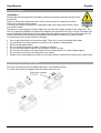
This device is a switching type power supply and can work with supply voltages in the range 100 - 240
VAC For worldwide usability four different AC adapters are enclosed: Euro type, UK type, US/Japan type
and Australia/New Zealand type. Use the appropriate AC adapter as shown in the picture and ensure it
is firmly secured in place and does not detach by pulling before installing into a power socket.
To reduce risk of fire, electric shocks or damage:
Do not open the product nor its power supply. There are no user serviceable parts inside.
Only qualified servicing personnel may carry out any repairs or maintenance.
Never use damaged cables.
Do not expose the product to water or places of moisture.
Do not use this product outdoors it is intended for indoor use only.
Do not place the product near direct heat sources. Always place it in a well-ventilated place.
Do not place heavy items on the product or the cables.
Please ensure any adapters are firmly secured and locked in place before inserting into a wall socket
Instructions for Use of Power Supply
Insert the required plug into the adapter pushing it until locked into place.
To unlock and remove the adapter push the button and pull it out.

User Manual English
Introduction
Thank you for purchasing the KVM over IP Access DVI-I, USB & PS/2. This product has been designed
to provide trouble free, reliable operation. It benefits from both a LINDY 2-year warranty and free lifetime
technical support. To ensure correct use, please read this manual carefully and retain it for future
reference.
KVM over IP Access DVI-I, USB & PS/2 is an IP-based KVM link Extender for remote server management.
It allows virtual management of server, PCs or KVM with DVI and USB ports over the Internet. It supports
secured access with password authentication and encrypted session and can be accessed via IP.
Package Contents
KVM over IP Access
1 x DVI-D cable, 1.2m
2 x DVI-A Male to VGA Female adapter
1 x USB Type A to Type B cable, 1.2m
1 x PS/2 to dual PS/2 KM cable, 1.2m
1 x 3 pin Jack to serial D9 cable, 1m
5VDC 3A Multi-country Power Supply (UK, EU, US & AUS), Barrel Size: 5.5/2.5mm DC Jack
This Manual
Features
IP based KVM remote control solution for server or PC management
Supports DVI Single Link and VGA resolutions up to 1920x1200
USB and PS/2 ports for source connection
USB 2.0 ports for console connection
USB Wi-Fi port to support a USB Wi-Fi dongle (not included, chipset supported is Realtek RTL8192CU)
Inbuilt 2 port fast Ethernet Hub
Supports virtual media and ISO
Specification
Supports DVI 1.0, USB 2.0 specification
DVI-I port for digital or analogue video signal
Intelligent compression technology for optimised video transmission
Various security options and access for users with different levels of permission
Operating Temperature: 0°C - 40°C (32°F - 104°F)
Storage Temperature: -20°C - 60°C (-4°F - 140°F)
Humidity: 0 - 90% RH (non-condensing)
Black, metal housing
Power Requirements: AC100-240V 50/60Hz
Power Consumption: 15W

User Manual English
Installation
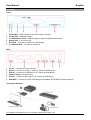
Front
1. Video LED – Lights up when remote IP session is active
2. Power LED – Indicates Power
3. 2 x USB Device Ports – USB HID ports to plug in keyboard and mouse
4. Debug port – For service use
5. DVI-I Out – Connect to a DVI-D or VGA display
6. 2 x Ethernet Hub – Connect to a network
Rear
1. DC 5V – Connect the 5VDC 3A PSU
2. DVI-I In – Connect to a DVI or VGA PC, Server or KVM device
3. USB In – Connect to a USB port of PC, Server or KVM device
4. Power Control – For future use
5. PS/2 In – Connect to PS/2 port of PC, Server or KVM device
6. USB WiFi – Connect to a WiFi USB dongle with Realtek RTL8192CU chipset (optional)
Connection Diagram
The diagram illustrated here is an example, applications may vary.

User Manual English
Getting Started
Important! Before starting the installation, please ensure that all devices are powered off.
The following steps are for a basic installation using DVI equipment in a standard KVM installation, if you
are using VGA equipment, please substitute the DVI-A to VGA adapter (included) and a VGA cable (not
included) with DVI cables where required.
1. Connect your DVI equipped PC to a DVI-I In port using a DVI cable.
2. Connect your PC to the USB In port using a USB Type A/B cable or to the PS/2 In port using the
PS/2 to dual PS/2 cable.
3. Connect a DVI display to the DVI-I Out port using a DVI cable and USB keyboard & mouse to the
USB device ports.
4. Connect one Ethernet port to a network using a Cat.5e cable.
5. Plug the DC power supply into the DC 5V power socket and switch on.
6. Power on your Computer and display to complete the installation.
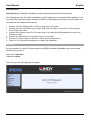
Operation
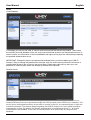
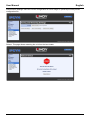
By factory default, the KVM IP Access address is HTTPS://192.168.1.200:5908 using a web browser,
default log-in account is:
User name: superuser
Password: superu
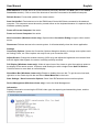
After first log in the following page will appear

User Manual English
Web management configuration
Download
Refer to the chapter Viewer Configuration below.
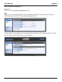
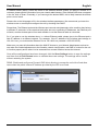
Main
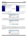
Date and Time: Connect the IPKVM to internet and select Synchronize with an Internet Time Server
(NTP) to set up the Local Time. Click on Store Settings so save.
Security: Specify the encryption level of connections, the certificates, and the password policy choosing
from No Password, Global Password, or User Password.

User Manual English
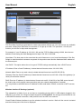
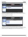
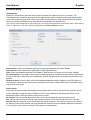
Networks:
TCP Port Base: Specify the port base for viewer connections with the unit. You can choose any available
port base, starting from 5900 with an increment of 10 right up to 6400. TCP port base + 8 is the port
number you will use for https web management.
For example, if your IP address is 192.168.1.192 and the TCP Port Base setting is 5920, then the new
address for accessing the Web Management is https://192.168.1.192:5928.
Host Name: The host name is the name that the unit will assume on your Local Area Network. Click Set
Default to load the default hostname composed of the product name and the Hardware MAC address of
the Ethernet port.
Use DHCP: This option allows the unit to get all TCP/IP settings automatically from a DHCP server.
IP Address: Enter a fixed IP address (in dotted decimal format such as 192.168.1.200).
Network Mask: Enter a net mask value (in dotted decimal format such as 255.255.255.0).
Gateway: Enter the fixed IP address (in dotted decimal format such as 192.168.1.254) of the gateway (i.e.
router) to access the Internet.
DNS: Enter the IP address (in dotted decimal format such as 80.10.246.30) of the DNS server that will
be used by the unit for domain name resolution (ask your network administrator if needed).
You may enable a valid DNS server IP address to allow email alerts, DDNS, connection to NTP servers,
etc.
Wireless Interface IP Settings (optional)
This subsection is hidden if you do not have a compatible wireless 802.11 USB adapter plugged in the
USB Wi-Fi port of the unit. Dongle’s chipset supported is RTL8192CU. It's strongly recommended to use
a WPA/WPA2 wireless connection, older protocols such as WEP are unsecure.
Check Enable Wireless Interface to put the wireless interface in service. Wait until the service is started
and the wireless part of this form is displayed.

User Manual English
In Network Name (SSID), select the name of the wireless network (SSID) you want to connect to. If
unknown, please get this information from your network administrator. If the wanted SSID does not appear
in the list, click on Scan. Eventually, if you cannot get the desired SSID, this is likely because the access
point is out of reach.
Please refer to the Help page to fill in the wireless interface parameters. We recommend you leave the
wireless router or access point configure the unit by checking Use DHCP.
Please Note: The Ethernet port and the Wireless port can work simultaneously at the condition they belong
to different IP networks. In the case that both ports are set to conflicting IP addresses, the Ethernet port
will work, and the wireless port will not work whether or not the Ethernet cable is connected.
So, if you plan to use the wireless alone, i.e. without Ethernet cable, please give to the Ethernet port a
fake IP address in a different network. For example, if the IP address of the wireless port belongs to
192.168.1.xxx, you could set the Ethernet Port to 192.168.2.xxx (netmask = 255.255.255.0).
Make sure you pass all information about the KVM IP Access to your Network Administrator so that he
can make the needed adjustments to the firewalls, network configuration, and DMZ of routers for the unit
to function properly and to allow it to be accessed from remote locations across the Internet.
Once all the configurations have been changed, click the Store Settings button to save the settings
and then click the Soft Restart button to validate these new settings. The settings will be invalid
without restarting the system.
DDNS: Enable and configure a Dynamic DNS client allowing to access the unit with a fixed alias
name when the public Internet IP address provided by the ISP is not fixed.

User Manual English
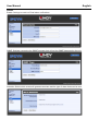
Virtual media
Remote Media
When running a viewer, you can share a DVD/CDROM, USB key, or ISO file with the computer attached
to the unit. For example, a CDROM in the drive of the computer running the viewer can appear like a
removable mass storage to the KVM IP Access-attached computer. Thus, from your remote location, you
can transfer files, install new programs or even install a complete OS into the attached computer. Note
that the transfer speed is limited by the network bandwidth, so it cannot be as fast as a direct
attachment.
If you share one of your hard drives, the attached computer can also write to your disk, provided you did
not check the option Disable Writes.
This page shows the current status of the connected Virtual Media and allows to forcefully disconnect it.
Specify whether the attached computer can or cannot write to the Virtual Media.
KVM Server
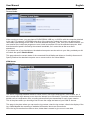
Server Log
The Server Log keeps detailed record of events, errors, user logins and logouts, video modes, etc. It
also records each login attempt, even when the attempt is not successful. It provides certain technical
details such as compression ratio, encoding scheme and bytes transmitted in each viewer session.
This is the place where you should go first to know the usage and state of your KVM IP Access.
This page is the place where you can see the log content, clear the log content, refresh the display of the
log, enable/disable the recording of statistical information about user connections.
Once the log file reaches its maximum size, oldest data is erased to give room to new data.

User Manual English
Each log entry is composed of the date plus time stamp, and the description of the event. The first letter
"K", "H" or "U" indicates whether the message is coming from the KVM server, the HTTP server, or the
USB server.
Video Capture
Please note that the digital video capture is always set to optimal quality and speed. This page is not
relevant for digital video signals. If the video is VGA, this page is the place where you can set up the
level of quality and speed of the video capture.
These settings can be used to balance the Video Quality against the Data Volume. Higher video quality
will generate larger data volume which will slow down the video transmission, especially across slow
Internet connections. Try to find a tradeoff between quality and speed.
Viewer Connection
This page allows adjustment of settings related to the viewer usage:
• IPKVM name as it is displayed on the title bar of the viewer window
• Keyboard layout that should be consistent with the keyboard you use on your computer and that is
setup in the attached computer

User Manual English
• Mouse re-synchronization hot keys
• Mouse shortcuts
• Special feature for anyone who uses a double-byte language such as Chinese, Japanese or
Korean (the CJK languages) and some other languages
• If the unit is connected to a KVM, you can also setup the KVM hotkeys that will allow selecting
the active port in a mouse click.
Computer
In this page you can provide some information concerning the attached computer:
• Computer Name
• Type of Operating System
• Digital or Analog Video Type
• Computer Attachment USB or PS/2*
• USB Mouse Relative or Absolute
*Please Note: PS/2 interface do not support hot-plug, when connecting a PS/2 computer select PS/2
Computer Attachment, click on Store Settings and then on Soft Restart. In the end connect the PS/2
cable included and power on the computer.
Power Control
For future use.

User Manual English
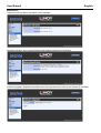
Users
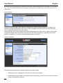
Local Database
In this page you can list, edit, add, or remove user accounts that can access the product. These users
are stored in the local database of the unit, they need no external access to an authentication server. In
case of conflict, the information in the local database has higher priority than the information provided by
the possible authentication server.
IMPORTANT: Change the super user password immediately after you have installed your KVM IP
Access. Failing to change the password for the super user is a severe security risk and could result in
unauthorized access to the unit and to the host system. Please also make sure to store your new
password in a secure place where can always be recited when required!
Remote Server
In this page you will enable or disable the usage of a centralized server running a Radius service or
hosting a directory that can be accessed through the LDAP protocol (Active Directory for example). This
server can be interrogated each time a user tries to connect to the unit. Its responses grant or reject the
connection attempts. This feature allows integrating the KVM IP Access into a more global enterprise
management of users. By default, the Remote Authentication is configured as None, i.e., all remote
authentications are disabled. In this case, the authentication is all done locally by using the User
database.

User Manual English
Radius Accounting
The Radius Accounting allows the unit to record all user connection and disconnection events on a
remote Radius Accounting server. The Radius Accounting is not related to the RADIUS or LDAP server
features that can be used to authenticate users.
By default, the RADIUS Accounting is disabled.
Connected Users
This page shows a list of all users that are connected with a viewer to the computer.
Note: This list of connected users is not generated when the password policy is No Password or Global
Password since by adopting these policies you imply that the distinction of user identities is not
necessary. Please refer to the Security page for more information about password policies.

User Manual English
Alarms
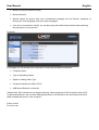
Emails: Settings to send out Email alarm notifications.
SNMP: Settings concerning the SNMP manager that will get the SNMP traps sent by the unit.
Selection: Select which events will generate an alarm and the type of alarm that must be sent.

User Manual English
Maintenance
Software Versions: Basic information on the software.
Networking Status: View current Ethernet and Wireless networking information.
Software Upgrade: Upgrade the software from this page across the LAN or the Internet (if available).

User Manual English
Save/Restore Settings: Save the current configuration for future usage or upload a previously saved
configuration file.
Reboot: This page allows restarting the unit from the boot loader.

User Manual English
Viewer Configuration
Viewer for Windows
Download and install the viewer by following the on-screen instruction.
Click the viewer link icon to launch the Windows viewer. If insufficient rights are granted to the
viewer, the User Access Control will pop up for authorization.
In the Connection Dialog, type the network information to access the unit, then click Connect. If the
unit is found, the viewer will come back and ask for User Authentication. Type the User ID, Password
and then click OK to access. By default, the user ID is superuser and the password is superu.
Viewer for Java
This viewer can be used on any system that supports the latest version of Java. If you continuously use
the current system to access through Java, recommend the jar file be save at a convenient location. Run
or double click the jar file and it will pop up the Connection Dialog similar to the Windows' viewer. If the
system doesn’t associate the Java virtual machine to the .jar file, open a text console and type "java -jar
mkview-dist.jar".

User Manual English
Connection Dialog
Compression
Specify the compression type that will be used to transmit the video from the unit to viewer. The
compressions are listed from the lowest to the highest data volume. Note that high compressions need
more work and thus longer KVM over IP and viewer processing times. High compressions are efficient
when the network bandwidth is low. Note that all compressions are with NO loss.
The volume of data depends on the video type. It is lower with digital than with analog video. With analog
video, it depends on the video quality setting (refer to Video Capture section).
Slow Internet: Video compression optimized for Internet bandwidth lower than 2Mbps.
Fast Internet: Video compression optimized for High Speed Internet.
LAN: Video compression optimized for 100BaseT. Note that the unit rarely use more than 10Mbps.
No Compression: This option is only useful for testing purposes. It does not provide better performance
than the LAN option. Note that "No Compression" means that a second level of data compression is not
applied.
Restrict to 8-bit: In worst cases, when the available bandwidth is below 1Mbps or even 500 Kbps, do
not hesitate to check this box to limit the color depth of the video to 8 bits. Most often is possible to work
with an 8-bit color video.
Local Cursor
There are two cursors when accessing a remote system with a viewer, the local cursor and the remote
cursor. Normally, except during movements, the two cursors should be superimposed. Refer to the
description below if there are some troubles on the cursor.
No Cursor: Due to personal preference, some may find confusing having two mouse cursors.
Dot: Having a dot as local cursor can help identifying which cursor is local and which one is remote.
Normal: Having a big local cursor accelerates the mouse utilization. The reason is that you can click on
an element in the screen without worrying whether the remote cursor has already reached this element
or not. Only the local cursor is relevant. This option is recommended.
La pagina si sta caricando...
La pagina si sta caricando...
La pagina si sta caricando...
La pagina si sta caricando...
La pagina si sta caricando...
La pagina si sta caricando...
-
 1
1
-
 2
2
-
 3
3
-
 4
4
-
 5
5
-
 6
6
-
 7
7
-
 8
8
-
 9
9
-
 10
10
-
 11
11
-
 12
12
-
 13
13
-
 14
14
-
 15
15
-
 16
16
-
 17
17
-
 18
18
-
 19
19
-
 20
20
-
 21
21
-
 22
22
-
 23
23
-
 24
24
-
 25
25
-
 26
26


Lindy KVM over IP Access DVI-I, USB & PS/2 Manuale utente
- Categoria
- Switch KVM
- Tipo
- Manuale utente
in altre lingue
Documenti correlati
Altri documenti
-
Belkin CONSOLE DE PRISE EN MAIN SÉCURISÉE VIA CONNEXION IP #F1DE101HEA Manuale del proprietario
-
ATEN CN8000 Guida Rapida
-
HP BL260c - ProLiant - G5 Manuale utente
-
Atlantis NetDVR V400 Manuale utente
-
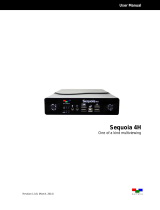 Avitech Sequoia 4H Manuale utente
-
ATEN CN8000A Guida Rapida
-
Emerson Avocent Universal Management Gateway Technical Manual
-
Eneo ITB-7SF0019M0A Quick Installation Manual
-
Digital Watchdog DW-VP16xT16P Manuale utente
-
