
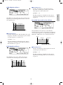
Menü
TONE GENERATOR/REALTIME CONTROL/EXTENDED SYNTHESIS
TONE GENERATOR/REALTIME CONTROL/EXTENDED SYNTHESIS
OWNER’S MANUAL
OWNER’S MANUAL
MUSIC SYNTHESIZER/REALTIME CONTROL/EXTENDED SYNTHESIS
MUSIC SYNTHESIZER/REALTIME CONTROL/EXTENDED SYNTHESIS
OWNER’S MANUAL

PRODUCT SAFETY MARKINGS: Yamaha electronic
products may have either labels similar to the graphics shown
below or molded/stamped facsimiles of these graphics on the
enclosure. The explanation of these graphics appears on this
page. Please observe all cautions indicated on this page and
those indicated in the safety instruction section.
ENVIRONMENTAL ISSUES: Yamaha strives to produce
products that are both user safe and environmentally friendly.
We sincerely believe that our products and the production
methods used to produce them, meet these goals. In keeping
with both the letter and the spirit of the law, we want you to be
aware of the following:
Battery Notice: This product MAY contain a small non-
rechargable battery which (if applicable) is soldered in place.
The average life span of this type of battery is approximately
five years. When replacement becomes necessary, contact a
qualified service representative to perform the replacement.
Warning: Do not attempt to recharge, disassemble, or
incinerate this type of battery. Keep all batteries away from
children. Dispose of used batteries promptly and as regulated
by applicable laws. Note: In some areas, the servicer is
required by law to return the defective parts. However, you do
have the option of having the servicer dispose of these parts
for you.
Disposal Notice: Should this product become damaged
beyond repair, or for some reason its useful life is considered
to be at an end, please observe all local, state, and federal
regulations that relate to the disposal of products that contain
lead, batteries, plastics, etc.
NOTICE: Service charges incurred due to lack of knowledge
relating to how a function or effect works (when the unit is
operating as designed) are not covered by the manufacturer’s
warranty, and are therefore the owners responsibility. Please
study this manual carefully and consult your dealer before
requesting service.
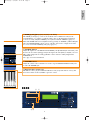
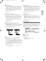
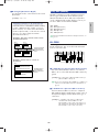
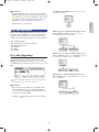
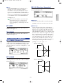
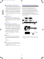
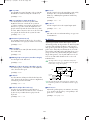
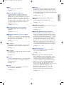
NAME PLATE LOCATION: The graphic below indicates the
location of the name plate. The model number, serial number,
power requirements, etc., are located on this plate. You should
record the model number, serial number, and the date of
purchase in the spaces provided below and retain this manual
as a permanent record of your purchase.
Model
Serial No.
Purchase Date
CAUTION
CAUTION
EX5/EX7
EX5R
CAUTION: TO REDUCE THE RISK OF ELECTRIC SHOCK.
DO NOT REMOVE COVER (OR BACK).
NO USER-SERVICEABLE PARTS INSIDE.
REFER SERVICING TO QUALIFIED SERVICE PERSONNEL.
The exclamation point within the equi-
lateral triangle is intended to alert the
user to the presence of important oper-
ating and maintenance (servicing)
instructions in the literature accompa-
nying the product.
The lightning flash with arrowhead
symbol, within the equilateral triangle,
is intended to alert the user to the pres-
ence of uninsulated “dangerous volt-
age” within the product’s enclosure
that may be of sufficient magnitude to
constitute a risk of electrical shock.
IMPORTANT NOTICE: All Yamaha electronic products are
tested and approved by an independent safety testing
laboratory in order that you may be sure that when it is
properly installed and used in its normal and customary
manner, all foreseeable risks have been eliminated. DO NOT
modify this unit or commission others to do so unless
specifically authorized by Yamaha. Product performance
and/or safety standards may be diminished. Claims filed under
the expressed warranty may be denied if the unit is/has been
modified. Implied warranties may also be affected.
SPECIFICATIONS SUBJECT TO CHANGE: The information
contained in this manual is believed to be correct at the time
of printing. However, Yamaha reserves the right to change or
modify any of the specifications without notice or obligation to
update existing units.
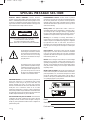
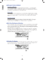
SPECIAL MESSAGE SECTION
92-469- 1
RISK OF ELECTRIC SHOCK
DO NOT OPEN
CAUTION
FCC 5/21/98 3:03 PM Page 2

92-469- 3
IMPORTANT SAFETY INSTRUCTIONS
INFORMATION RELATING TO PERSONAL INJURY, ELECTRICAL SHOCK,
AND FIRE HAZARD POSSIBILITIES HAS BEEN INCLUDED IN THIS LIST.
WARNING- When using any electrical or electronic product,
basic precautions should always be followed. These
precautions include, but are not limited to, the following:
1. Read all Safety Instructions, Installation Instructions,
Special Message Section items, and any Assembly
Instructions found in this manual BEFORE making any
connections, including connection to the main supply.
2. Do not attempt to service this product beyond that
described in the user-maintenance instructions. All other
servicing should be referred to qualified service personnel.
3. Main Power Supply Verification: Yamaha products are
manufactured specifically for the supply voltage in the area
where they are to be sold. If you should move, or if any doubt
exists about the supply voltage in your area, please contact
your dealer for supply voltage verification and (if applicable)
instructions. The required supply voltage is printed on the
name plate. For name plate location, please refer to the
graphic found in the Special Message Section of this manual.
4. DANGER-Grounding Instructions: This product must be
grounded and therefore has been equipped with a three pin
attachment plug. If this product should malfunction, the ground
pin provides a path of low resistance for electrical current,
reducing the risk of electrical shock. If your wall socket will not
accommodate this type plug, contact an electrician to have
the outlet replaced in accordance with local electrical codes.
Do NOT modify the plug or change the plug to a different type!
5. WARNING: Do not place this product or any other
objects on the power cord or place it in a position where
anyone could walk on, trip over, or roll anything over power or
connecting cords of any kind. The use of an extension cord is
not recommended! If you must use an extension cord, the
minimum wire size for a 25' cord (or less) is 18 AWG. NOTE:
The smaller the AWG number, the larger the current handling
capacity. For longer extension cords, consult a local
electrician.
6. Ventilation: Electronic products, unless specifically
designed for enclosed installations, should be placed in
locations that do not interfere with proper ventilation. If
instructions for enclosed installations are not provided, it must
be assumed that unobstructed ventilation is required.
7. Temperature considerations: Electronic products should
be installed in locations that do not seriously contribute to their
operating temperature. Placement of this product close to heat
sources such as; radiators, heat registers etc., should be
avoided.
8. This product was NOT designed for use in wet/damp
locations and should not be used near water or exposed to
rain. Examples of wet /damp locations are; near a swimming
pool, spa, tub, sink, or wet basement.
9. This product should be used only with the components
supplied or; a cart ,rack, or stand that is recommended by the
manufacturer. If a cart, rack, or stand is used, please observe
all safety markings and instructions that accompany the
accessory product.
10. The power supply cord (plug) should be disconnected
from the outlet when electronic products are to be left unused
for extended periods of time. Cords should also be
disconnected when there is a high probability of lightening
and/or electrical storm activity.
11. Care should be taken that objects do not fall and
liquids are not spilled into the enclosure through any openings
that may exist.
12. Electrical/electronic products should be serviced by a
qualified service person when:
a. The power supply cord has been damaged; or
b. Objects have fallen, been inserted, or liquids have
been spilled into the enclosure through openings; or
c. The product has been exposed to rain; or
d. The product does not operate, exhibits a marked
change in performance; or
e. The product has been dropped, or the enclosure of the
product has been damaged.
13. This product, either alone or in combination with an
amplifier and headphones or speaker/s, may be capable of
producing sound levels that could cause permanent hearing
loss. DO NOT operate for a long period of time at a high
volume level or at a level that is uncomfortable. If you
experience any hearing loss or ringing in the ears, you should
consult an audiologist.
IMPORTANT: The louder the sound, the shorter the time
period before damage occurs.
14. Some Yamaha products may have benches and/or
accessory mounting fixtures that are either supplied as a part
of the product or as optional accessories. Some of these items
are designed to be dealer assembled or installed. Please
make sure that benches are stable and any optional fixtures
(where applicable) are well secured BEFORE using. Benches
supplied by Yamaha are designed for seating only. No other
uses are recommended.
PLEASE KEEP THIS MANUAL
FCC 5/21/98 3:03 PM Page 3

1. IMPORTANT NOTICE: DO NOT MODIFY THIS UNIT!
This product, when installed as indicated in the instructions
contained in this manual, meets FCC requirements. Modifications
not expressly approved by Yamaha may void your authority, granted
by the FCC, to use the product.
2. IMPORTANT: When connecting this product to accessories and/or
another product use only high quality shielded cables. Cable/s
supplied with this product MUST be used. Follow all installation
instructions. Failure to follow instructions could void your FCC
authorization to use this product in the USA.
3. NOTE: This product has been tested and found to comply with the
requirements listed in FCC Regulations, Part 15 for Class “B” digital
devices. Compliance with these requirements provides a
reasonable level of assurance that your use of this product in a
residential environment will not result in harmful interference with
other electronic devices. This equipment generates/uses radio
frequencies and, if not installed and used according to the
instructions found in the users manual, may cause interference
harmful to the operation of other electronic devices. Compliance
with FCC regulations does not guarantee that interference will not
occur in all installations. If this product is found to be the source of
interference, which can be determined by turning the unit “OFF”
and “ON”, please try to eliminate the problem by using one of the
following measures:
Relocate either this product or the device that is being affected by
the interference.
Utilize power outlets that are on different branch (circuit breaker or
fuse) circuits or install AC line filter/s.
In the case of radio or TV interference, relocate/reorient the
antenna. If the antenna lead-in is 300 ohm ribbon lead, change the
lead-in to co-axial type cable.
If these corrective measures do not produce satisfactory results,
please contact the local retailer authorized to distribute this type of
product. If you can not locate the appropriate retailer, please contact
Yamaha Corporation of America, Electronic Service Division, 6600
Orangethorpe Ave, Buena Park, CA90620
The above statements apply ONLY to those products distributed by
Yamaha Corporation of America or its subsidiaries.
ADVARSEL!
Lithiumbatteri—Eksplosionsfare ved fejlagtig håndtering. Udskiftning
må kun ske med batteri af samme fabrikat og type. Levér det brugte
batteri tilbage til leverandoren.
VARNING
Explosionsfara vid felaktigt batteribyte. Använd samma batterityp
eller en ekvivalent typ som rekommenderas av apparattillverkaren.
Kassera använt batteri enlight fabrikantens instruktion.
VAROITUS
Paristo voi räjähtää, jos se on virheellisesti asennettu. Vaihda paristo
ainoastaan laitevalmistajan suosittelemaan tyyppiin. Hävitä käytetty
paristo valmistajan ohjeiden mukaisesti.
NEDERLAND
NETHERLAND
• Dit apparaat bevat een lithium batterij voor geheugen back-up.
• This apparatus contains a lithium battery for memory back-up.
• Raadpleeg uw leverancier over de verwijdering van de batterij op
het moment dat u het apparaat ann het einde van de levensduur
afdankt of de volgende Yamaha Service Afdeiing:
Yamaha Music Nederland Service Afdeiing
Kanaalweg 18-G, 3526 KL UTRECHT
Tel. 030-2828425
• For the removal of the battery at the moment of the disposal at the
end of the service life please consult your retailer or Yamaha
Service Center as follows:
Yamaha Music Nederland Service Center
Address : Kanaalweg 18-G, 3526 KL UTRECHT
Tel : 030-2828425
• Gooi de batterij niet weg, maar lever hem in als KCA.
• Do not throw away the battery. Instead, hand it in as small chemical
waste.
IMPORTANT NOTICE FOR THE UNITED
KINGDOM
Connecting the Plug and Cord
WARNING: THIS APPARATUS MUST BE EARTHED
IMPORTANT. The wires in this mains lead are coloured in
accordance with the following code:
GREEN-AND-YELLOW: EARTH
BLUE : NEUTRAL
BROWN : LIVE
As the colours of the wires in the mains lead of this apparatus
may not correspond with the coloured markings identifying the
terminals in your plug proceed as follows:
The wire which is coloured GREEN-and-YELLOW must be
connected to the terminal in the plug which is marked by the
letter E or by the safety earth symbol or colored GREEN or
GREEN-and-YELLOW.
The wire which is coloured BLUE must be connected to the
terminal which is marked with the letter N or coloured BLACK.
The wire which is coloured BROWN must be connected to the
terminal which is marked with the letter L or coloured RED.
* This applies only to products distributed by YAMAHA CORPORATION OF AMERICA.
FCC INFORMATION (U.S.A.)
• This applies only to products distributed by Yamaha-Kemble Music (U.K.) Ltd.
FCC 5/21/98 3:03 PM Page 4

PRECAUTIONS
PLEASE READ CAREFULLY BEFORE PROCEEDING
* Please keep these precautions in a safe place for future reference.
WARNING
Always follow the basic precautions listed below to avoid the possibility of serious injury or even death from electrical shock,
short-circuiting, damages, fire or other hazards. These precautions include, but are not limited to, the following:
• This instrument contains no user-serviceable parts. Do not attempt to
disassemble or modify the internal components in any way.
• Do not expose the instrument to rain, use it near water or in damp or wet
conditions, or place containers on it containing liquids which might spill into
any openings.
• If the power cord or plug becomes frayed or damaged, or if there is a sudden
loss of sound during use of the instrument, or if any unusual smells or smoke
should appear to be caused by it, immediately turn off the power switch,
disconnect the electric plug from the outlet, and have the instrument
inspected by qualified Yamaha service personnel.
• Only use the voltage specified as correct for the instrument. The required
voltage is printed on the name plate of the instrument.
• Always connect the three-pin attachment plug to a properly grounded power
source. (For more information about the main power supply, see page 16.)
• Before cleaning the instrument, always remove the electric plug from the
outlet. Never insert or remove an electric plug with wet hands.
• Check the electric plug periodically and remove any dirt or dust which may
have accumulated on it.
CAUTION
Always follow the basic precautions listed below to avoid the possibility of physical injury to you or others, or damage to the
instrument or other property. These precautions include, but are not limited to, the following:
• Do not place the power cord near heat sources such as heaters or radiators,
and do not excessively bend or otherwise damage the cord, place heavy
objects on it, or place it in a position where anyone could walk on, trip over,
or roll anything over it.
• When removing the electric plug from the instrument or an outlet, always hold
the plug itself and not the cord. Pulling by the cord can damage it.
• Do not connect the instrument to an electrical outlet using a multiple-
connector. Doing so can result in lower sound quality, or possibly cause
overheating in the outlet.
• Remove the electric plug from the outlet when the instrument is not to be used
for extended periods of time, or during electrical storms.
• Before connecting the instrument to other electronic components, turn off the
power for all components. Before turning the power on or off for all
components, set all volume levels to minimum.
• Do not expose the instrument to excessive dust or vibrations, or extreme cold
or heat (such as in direct sunlight, near a heater, or in a car during the day) to
prevent the possibility of panel disfiguration or damage to the internal
components.
• Do not use the instrument near other electrical products such as televisions,
radios, or speakers, since this might cause interference which can affect
proper operation of the other products.
• Do not place the instrument in an unstable position where it might
accidentally fall over.
• Before moving the instrument, remove all connected cables.
• When cleaning the instrument, use a soft, dry cloth. Do not use paint
thinners, solvents, cleaning fluids, or chemical-impregnated wiping cloths.
Also, do not place vinyl, plastic or rubber objects on the instrument, since
this might discolor the panel or keyboard.
• Do not rest your weight on, or place heavy objects on the instrument, and do
not use excessive force on the buttons, switches or connectors.
• Use only the stand/rack specified for the instrument. When attaching the stand
or rack, use the provided screws only. Failure to do so could cause damage to
the internal components or result in the instrument falling over.
• Do not operate the instrument for a long period of time at a high or
uncomfortable volume level, since this can cause permanent hearing loss. If
you experience any hearing loss or ringing in the ears, consult a physician.
■ REPLACING THE BACKUP BATTERY
• This instrument contains a non rechargeable internal backup battery which
permits internal data to remain stored even when the power is off. When the
backup battery needs replacing, the message "Change internal battery!" will
display in the LCD. When this happens, immediately back up your data, then
have qualified Yamaha service personnel replace the backup battery.
• Do not attempt to replace the backup battery yourself, in order to prevent the
possible serious hazards. Always have qualified Yamaha service personnel
replace the backup battery.
• Never place the backup battery in a location that a child can reach, since a
child might accidentally swallow the battery. If this should happen, consult a
physician immediately.
■ SAVING USER DATA
• Always save data to a floppy disk frequently, in order to help prevent the loss
of important data due to a malfunction or user operating error.
Yamaha cannot be held responsible for damage caused by improper use or
modifications to the instrument, or data that is lost or destroyed.
Always turn the power off when the instrument is not in use.
(2)AC-2
Intro/E/qx 5/21/98 11:26 AM Page 5

6
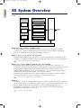
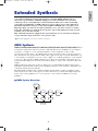
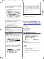
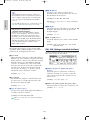
The Yamaha EX5 and EX7 Music Synthesizers, and the EX5R Tone Generator, offer more
music performance and production power than ever before available in a single keyboard or
tone generator unit. All three models feature a unique Extended Synthesis system which
incorporates a number of the most advanced tone generator technologies currently available
… plus a full-featured sampling system. There’s also a top-quality internal effect system so
no extra sound-processing equipment is required. 16-track song and 8-track pattern
sequencers provide sophisticated on-board sequence programming and editing capability,
while a unique 4-track arpeggiator function adds extended performance and
accompaniment capability. The EX-series keyboards and tone generator also offer one of the
most versatile and intuitive real-time control systems available, and they’re expandable to
suit a wide range of professional systems and requirements.
We urge you to read through at least the introductory section of this owner’s manual while
familiarizing yourself wit your EX5, EX5R, or EX7, and keep th manual in a safe place for
future reference.
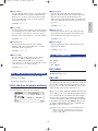
About the Manual
This owner’s manual is divided into two main sections: The Introductory Section, and the Reference
Section:
■Introductory Section
This section has been designed to provide you with an overall understanding of the EX5, EX5R, and EX7, as
well as some hints as how to use these advanced instruments most effectively. It will also refer you to
corresponding sections in the Reference section, so you can refer to the pertinent details as necessary. Use the
Introductory Section as a guide and directory to the main features and functions of the EX5, EX5R, and EX7.
■Reference Section
The Reference Section contains full details and instructions for all of the EX features and functions. You
should be able to find the information you need via the table of contents, the index at the back of the manual,
or via the Introductory Section, described above.
(EX5/5R)
Products bearing the SONDIUS-XG logo are licensed under patents of Stanford University and Yamaha as listed
on the internet web site, <http://www.sondius-xg.com>.
This product is not compatible with the XG format or XG song data.
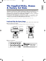
Included Accessories
Demonstration Disk 1-4
Owner’s Manual
Data List
AC Power Cord
Copying of the commercially available music sequence data and/or digital audio files is strictry prohibited except for your
personal use.
The illustrations and LCD screens as shown in this owner’s manual are for instructional purposes only, and may appear
somewhat different from those on your instrument.
The company names and product names in this Owner’s Manual are the trademarks or registered trademarks of their
respective companies.
Intro/E/qx 6/12/98 5:55 PM Page 6

7
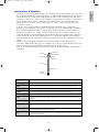
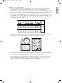
Introductory Section
The Controls & Connectors ................................8
Setting Up ........................................................16
The Supplied Disks, Demos, & Factory Set Data
....25
EX System Overview ........................................28
Extended Synthesis ..........................................29
AWM Synthesis ....................................................29
Virtual Acoustic Synthesis (EX5/5R) ................30
AN Synthesis (Analog Physical Modeling)
............33
FDSP Synthesis
(Formulated Digital Signal Processing) ..............34
Voice and Performance Selection......................36
Voice Structure & Editing Hints ......................40
System Overview ..................................................40
Polyphony..............................................................45
Editing Control ....................................................45
Voice Store Procedure ..........................................48
The Power of the Performance Mode ..............49
Performance Store Procedure ..............................53
Performance Mode DSP Limitations ..................54
The Controllers ................................................55
The EX Controllers ..............................................55
Scene Switching & Morphing..............................57
Controller Sets ......................................................58
Sequencer Functions ........................................60
Sequencer Record Modes & Editing....................62
Play Effects & Groove Quantization ..................64
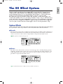
The EX Effect System ......................................65
Sampling ..........................................................69
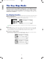
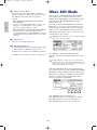
The Key Map Mode ..........................................72
Reference Section
Voice Mode........................................................75
Voice Play Mode....................................................75
Voice Edit Mode....................................................76
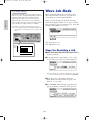
Voice Job Mode ..................................................148
Wave Edit Mode..................................................150
Wave Job Mode ..................................................154
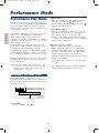
Performance Mode ..........................................156
Performance Play Mode ....................................156
Performance Edit Mode ....................................158
Performance Job Mode ......................................172
Sample Mode ..................................................175
Sample Play Mode ..............................................175
Sample Record Mode..........................................176
Sample Edit Mode ..............................................179
Sample Job Mode ................................................182
Song Mode ......................................................185
Song Play Mode ..................................................185
Song Record Mode..............................................193
Song Edit Mode ..................................................201
Song Job Mode....................................................206
Pattern Mode ..................................................219
Pattern Play Mode ..............................................219
Pattern Record Mode..........................................223
Pattern Edit Mode ..............................................226
Pattern Job Mode................................................227
Arpeggio Mode................................................238
Arpeggio Record Mode ......................................245
Arpeggio Edit Mode ..........................................247
Arpeggio Job Mode ............................................249
Disk Mode ......................................................259
Utility Mode....................................................270
Appendix ........................................................278
Optional Boards/Memories................................278
Troubleshooting..................................................291
LCD Messages ....................................................294
Specifications ......................................................295
Index....................................................................296
Contents
Introductory
Section
Reference
Section
Voice Mode
Performance
Mode
Sample Mode
Song Mode
Pattern Mode
Arpeggio
Mode
Disk Mode
Utility Mode
Appendix
Intro/E/qx 5/21/98 11:26 AM Page 7

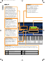
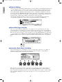
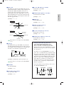
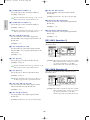
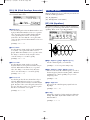
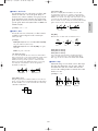
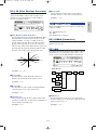
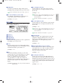
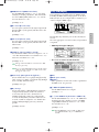
SCENE
2
1
OCTAVE
DOWN UP
PITCH MODULATION 1 MODULATION 2
A D GAIN
VOLUME
MODE
EX5/7
1
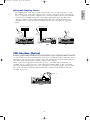
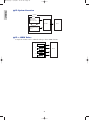
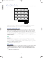
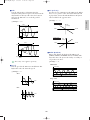
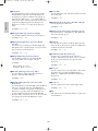
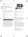
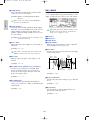
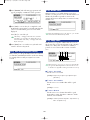
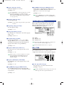
OCTAVE [DOWN] and [UP] Keys (EX5 and EX7 only)
Shift the pitch of the keyboard up or down up to five octaves in
one-octave steps. The pitch is shifted one octave in the
corresponding direction, up to the maximum, each time one of
these keys is pressed. When the current octave is higher than
the normal octave the UP indicator will be lit, and vice versa.
Neither indicator will be lit when the normal octave is selected.
2
[PITCH] Wheel (EX5 and EX7 only)
This self-centering pitch wheel allows smooth upward and
downward pitch bends. A range of other control functions can
be assigned to the PITCH wheel.
➡
See page 55 for more information.
3
[MODULATION 1] and [MODULATION 2] Wheels
(EX5 and EX7 only)
Can be assigned to any of the extensive range of controller
parameters for extraordinary expressive control. The
MODULATION 2 wheel can also be used for “scene
morphing” — i.e. smoothly changing from one memorized
scene to the other.
➡
See page 55 for more information.
4
Ribbon Controller (EX5 and EX7 only)
Another expressive EX controller, the Ribbon Controller is
touch sensitive, and is controlled by running a finger lightly
across its surface to the left or right. The Ribbon Controller can
be assigned to the full range of EX parameters.
➡
See page 56 for more information.
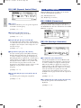
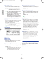
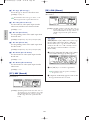
9
Floppy Disk Drive
The built-in floppy disk drive allows easy, economical, high-
volume storage of voice data. The disk-in-use LED indicator
below the drive slot lights while any disk operation is in
progress (NEVER attempt to remove a disk or turn the power
off while a disk operation is in progress). The eject key, also
below the disk slot, is used to remove disks from the drive.
➡
See page 259 for more information.
8
Introductory
Section
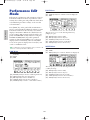
Introductory Section
The Controls & Connectors
The following brief descriptions of the EX controls and connectors should help you to understand the
overall logic of the interface.
Front Panel
Intro/E/qx 5/21/98 11:27 AM Page 8

9
Introductory
Section
123456
POWER
EXIT
SHIFT
TONE GENERATOR
REALTIME CONTROL
EXTENDED SYNTHESIS
1 2 3 4 5 6
VOICE PERFORM SONG PATTERN SA MPLE
JOB
LMONO R
BREATH PHONES
VOLUME
AD
INPUT
A D GAIN
STORE UTILIT Y
DISK
SC2
SC1
EDIT
COMPARE
KEYMAP BYPASS
ARPEG KNOB
CANCEL
CURSOR
DATA
TOP
REC STOP PLAY
POWER
REW FWD
ON OFF
DEC NO INC YES
SPACE
ABC
0
123
456
789
ENTER
DEF GHI JKL
MNO
PQR
STU
VWX YZ
F1 F2 F3 F4 F5 F6 F7 F8 EXIT
SHIFT
E
VOICE
PERFORMANCE
SONG
PAT TERN SAMPLE
EDIT
JOB STORE UTILITY DISK
FWDREWTOP
KNOB MODE
ARPEGGIO
COMPARE
KEYMAP EF BYPASS REC STOP PLAY
8
Keyboard (EX5 and EX7 only)
The EX5 has a 76-key keyboard while the EX7 has a 61-key keyboard. Both are velocity and
after-touch sensitive for broad, intimate expressive control.
6
A/D Gain Control
Adjusts the input level of the INPUT R and L/MONO jacks (the INPUT jack on the EX7), and
therefore the level of the signal appearing at the input of the A/D (Analog-to-Digital) converter.
This control is important for setting optimum record level when recording samples in the
SAMPLE mode.
➡
See page 70 for more information.
5
SCENE [1] and [2] Keys ([SC1] and [SC2] on the EX5R)
The SCENE [1] and [2] keys can be used to memorize and recall different settings of the
Controller Knobs, so a complete set of knob settings can be recalled instantaneously. Knob
scenes are stored by using the SCENE keys in conjunction with the STORE key (page 57).
When both SCENE indicators are lit (this is done by pressing one SCENE key while holding the
other), the MODULATION 2 wheel or a foot controller can be used to “morph” between the
two scenes stored in the SCENE [1] and [2] keys (page 57).
7
VOLUME Control
Adjusts the volume of the sound delivered via the rear-panel OUTPUT L/MONO and R jacks
as well as the PHONES jack.
EX5R
76
9 5
* 1, 2, 3, 4 and 8 are not available on EX5R.
Intro/E/qx 5/21/98 11:27 AM Page 9

10
Introductory
Section
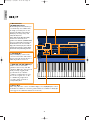
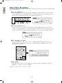
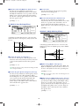
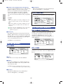
MODE
VOICE
PERFORMANCE
SONG
PAT TERN SAMPLE
EDIT
JOB STORE UTILITY DISK
FWDREWTOP
KNOB MODE
ARPEGGIO
COMPARE
KEYMAP EF BYPASS REC STOP PLAY
F1 F2 F3 F4 F5 F6 F7 F8
1 2 3 4 5 6
CANCEL
CURSOR
DATA
DEC NO
INC
YES
EXIT
SHIFT
EX5/7
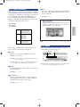
% MODE Keys
The MODE keys select the corresponding
EX modes, or appropriate sub-modes. The
upper row of MODE keys engage the
primary modes, and have LED indicators
to show which mode(s) are currently
active. The lower row of MODE keys
select secondary or utility modes.
You can not enter Pattern mode when
[ARPEGGIO] key or [KEYMAP] key is turned on.
! [ARPEGGIO] Key
([ARPEG] on the EX5R)
This key turns the advanced automatic
arpeggiator on or off. When the
arpeggiator is turned on, the Voice or
Performance Edit mode Arpeggiator edit
display will appear.
➡
See page 238 for more information.
[ARPEGGIO] key functions (can be turned on or
off) when in Voice mode, Performance mode and
Song Play mode.
@ [KEY MAP] Key
Engages the Key Map mode in which
samples, entire patterns, or pattern
tracks can be individually assigned to
separate keys on the keyboard.
➡
See page 72 for more information.
[KEYMAP] key functions (can be turned on or
off) when in Voice mode, Performance mode
and Song mode.
# [EF BYPASS] Key
([BYPASS] on the EX5R)
Turns the type of effects specified in the
Utility mode Other Setup display on or
off. When engaged (i.e. when the
indicator is lit) the specified effects are
bypassed.
➡
See page 276 for more information.
$ Sequencer Keys
The sequencer keys control recording and playback in the Song, Pattern, and Arpeggio modes, and allow you to
locate a specific measure within a song or pattern. Their layout and functions are similar to the transport controls
on a tape recorder.
) [KNOB MODE] Key
([KNOB] on the EX5R)
The six Controller Knobs, described
below, can function either as sound
controllers or data entry knobs. In the
Song, Pattern, Sample, Edit, Job, Store,
Utility and Disk modes the [KNOB
MODE] key switches between data entry
and sound control, allowing you to try out
the effect of knob-related settings without
having to exit from the Edit mode. The
knobs function only as sound controllers
in the Voice and Performance modes.
[
I
]
REC
[
J
]
STOP
[
F
]
START
[ ]
TOP
[
G
]
REW
[
H
]
FWD
Press this key to engage the record ready mode. You have to press the
START key to actually start recording.
Press to stop recording or playback.
Press to start recording or playback.
This key takes you directly to the first measure (the “top”) of the current song
or pattern.
Press briefly to move back one measure, or hold for continuous scrolling.
Press briefly to move forward one measure, or hold for continuous scrolling.
Intro/E/qx 5/21/98 11:27 AM Page 10

11
Introductory
Section
TONE GENERATOR
REALTIME CONTROL
EXTENDED SYNTHESIS
1 2 3 4 5 6
VOICE PERFORM SONG PATTERN SA MPLE
JOB
LMONO R
BREATH PHONES
VOLUME
AD
INPUT
A D GAIN
STORE UTILIT Y
DISK
SC2
SC1
EDIT
COMPARE
KEYMAP BYPASS
ARPEG KNOB
CANCEL
CURSOR
DATA
TOP
REC STOP PLAY
POWER
REW FWD
ON OFF
DEC NO INC YES
SPACE
ABC
0
123
456
789
ENTER
DEF GHI JKL
MNO
PQR
STU
VWX YZ
F1 F2 F3 F4 F5 F6 F7 F8 EXIT
SHIFT
ES
ABC
0
12
45
7
8
DEF GHI
MNO PQR
VWX YZ
& [F1] through [F8] Function, [SHIFT], and [EXIT] Keys
The functions of these keys depend on the selected mode. They are used to engage a function indicated on the
display immediately above the key or select a page of parameters.
When the “S” symbol appears in the lower left corner of the display, the [SHIFT] key can be used to select a
secondary function menu for the function keys: press the appropriate function key while holding the [SHIFT]
key to access a secondary function.
The [EXIT] key will return you to the next highest level in the display hierarchy when in an editing, utility, or
disk function display. In most cases you can return directly to the top-level primary mode display by directly
pressing the appropriate MODE key.
^ LCD Display Screen & Contrast Control
This large multi-function liquid crystal display screen shows all parameters and prompts you need to operate the
EX5, EX5R, or EX7 with optimum ease and efficiency.
Use the contrast control to achieve the best display visibility (LCD visibility varies greatly with viewing angle and
lighting).
* Controller Knobs
These knobs form an important part of the advanced EX user interface. They can can be assigned to control an
impressively wide range of sound parameters in real time during performance/playback, and they can function as
data entry controls in the editing, utility, disk, and some other modes. The [KNOB MODE] key, described above,
determines which function the knobs assume in the appropriate modes.
Normally when you rotate a controller knob being used for data entry, the corresponding value changes in
relative fashion — i.e. the knob increases or decreases the value of the parameter in relation to the value that was
initially on the display. If you rotate a controller knob while holding the [KNOB MODE] key, however, the
relationship between the controller position and the data value becomes absolute, and the central detented
position of the knob will correspond to the exact center of the parameter range.
The Voice mode lets you select, play, and edit individual voices.
The [VOICE] key indicator also blinks to indicate that a MIDI System
Exclusive message is being received. [→ page 75]
In the Performance mode you can select, play, and edit individual
“performance” programs including multiple layered or split voices and effects.
Press the [VOICE] key while holding the [PERFORMANCE] key to go
directly to the Voice Edit mode from the Performance mode.
The [PERFORMANCE] key indicator also blinks to indicate that a MIDI
System Exclusive message is being received. [→ page 156]
The Song mode provides access to the sophisticated sequence recording,
playback, and editing capabilities provided by the EX5, EX5R, and EX7.
[→ page 185]
Sequence “patterns” which can be used individually or incorporated into
complete songs in the Song mode can be recorded, played, and edited in
the Pattern mode. [→ page 219]
Advanced sample recording and editing features are available via the Sample
mode. [→ page 175]
The [EDIT] key accesses the appropriate editing functions for the currently
selected mode: Voice, Performance, Song, Pattern, or Sample.
Each of the primary modes — Voice, Performance, Song, Pattern, and
Sample — have a range of “jobs” which can be accessed by pressing the
[JOB] key.
This key is used to store edited data to an internal memory location, or
controller knob settings to either of the SCENE keys. [→ pages, 48, 53 and 57]
The UTILITY mode includes MIDI, system and other functions that are
essential for general operation. [→ page 270]
The Disk mode includes disk save and load functions as well as all other
functions you need for efficient data storage and management. [→ page 259]
!@ #) * $
&
%
^
EX5R
[VOICE]
[PERFORMANCE]
[SONG]
[PATTERN]
[SAMPLE]
[EDIT]
[JOB]
[STORE]
[UTILITY]
[DISK]
Intro/E/qx 5/21/98 11:27 AM Page 11

12
Introductory
Section
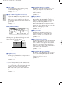
CURSOR
DATA
DEC NO
INC
YES
BANK
PROGRAM
PA RT
TRACK
ELEMENT SELECT ELEMENT ON OFF
COMMON OSC PITCH FILTER AMPLITUDE LFO CONTROL EFFECT
ABCDEFGH
12345678
12341234
910111213141516
SPACE
ABC
0
123
456
7
89
ENTER
DEF GHI JK L
MNO PQR
STU
VWX YZ
CANCEL
6
ELEMENT SELECT ELEMENT ON OFF
COMMON OSC PITCH FILTER AMPLITUDE LFO CONTROL EFFECT
ABCDEFGH
12345678
12341234
910111213141516
XIT
0
123
456
789
EX5/7
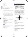
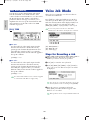
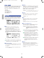
¡ [DEC/NO] and [INC/YES] Keys
Used to select voices and edit
parameter values in any of the EX
edit modes. Either key can be pressed
briefly for single stepping in the
specified direction, or held for
continuous scrolling. These keys are
also used to respond “Yes” or “No”
to confirmation prompts when
executing certain operations or
saving/loading data.
º [CANCEL] Key
The [CANCEL] key can be used to
cancel an entered value and return to
the previous value if pressed before a
different parameter is selected.
( Data Dial and
[CURSOR/DATA] Key
The Data Dial provides a fast, efficient way to
cover a broad range of voice numbers when,
for example, you’re looking for a voice but
don’t know the number. It's also handy for
making large value changes in any of the
editing and utility modes.
When editing the Data Dial will normally
increment or decrement the selected
parameter value. When the [CURSOR/DATA]
key is pressed and its indicator is lit, however,
the Data Dial moves the cursor around the
display rather than changing values. This can
be handy when navigating a complex display
which includes many individual parameters.
™ Cursor Keys
These 4 keys move the "cursor" around the display screen, highlighting the various
items that are available for selection or parameters that are available for editing (the
cursor appears as a dark block with inverse characters).
Intro/E/qx 5/21/98 11:27 AM Page 12

13
Introductory
Section
TONE GENERATOR
REALTIME CONTROL
EXTENDED SYNTHESIS
1 2 3 4 5 6
VOICE PERFORM SONG PATTERN SA MPLE
JOB
LMONO R
BREATH PHONES
VOLUME
AD
INPUT
A D GAIN
STORE UTILIT Y
DISK
SC2
SC1
EDIT
COMPARE
KEYMAP BYPASS
ARPEG KNOB
CANCEL
CURSOR
DATA
TOP
REC STOP PLAY
POWER
REW FWD
ON OFF
DEC NO INC YES
SPACE
ABC
0
123
456
789
ENTER
DEF GHI JKL
MNO
PQR
STU
VWX YZ
F1 F2 F3 F4 F5 F6 F7 F8 EXIT
SHIFT
MUSIC SYNTHESIZER
REALTIME CONTROL
EXTENDED SYNTHESIS
£ Numeric Keypad and [ENTER] Key
These keys allow direct entry of numeric values where applicable. Enter the required value
via the numeric keys — the entered number will flash on the displays — then press the
[ENTER] key to actually enter the specified value. The [ENTER] key is also used to enter
notes and other events when editing sequence data, and to execute a specified job or disk
function. The numeric keys are also used to specify note lengths and dynamics (velocity)
when step recording in the SONG or PATTERN mode.
➡
See page 199 for more information.
¢ Bank [A] Through [H] Keys (EX5 and EX7 only)
Each of the EX5 and EX7 voice memories — P1 (Preset 1), P2 (Preset 2), I1 (Internal 1)
and I2 (Internal 2) — has 128 voice memory locations arranged in 8 banks of 16 voices
each. The 128 performance memories are also organized in 8 banks of 16 performance
setups. These keys select the bank from which an individual voice or performance setup
will be selected. When editing voice parameters they are also used to select and mute
elements.
∞ Program Number [1] Through [16] Keys (EX5 and EX7 only)
The program number keys are used in conjunction with the bank keys to select any of the
128 voice memory locations within the currently selected voice memory — P1 (Preset 1), P2
(Preset 2), I1 (Internal 1) and I2 (Internal 2) — in the VOICE mode, or any of the 128
performance memory locations in the Performance mode. In the Voice Edit mode keys [1]
through [8] can be used to directly select the various edit displays.
™ ¡£
(º
EX5R
* ¢ and ∞ are not available on EX5R.
Intro/E/qx 5/21/98 11:27 AM Page 13

14
Introductory
Section
CAUTION
ATTENTION
WARNING
:RISQUE DE CHOC ELECTRIQUE NE PAS OUVRIR.
TO REDUCE THE RISK OF FIRE OR ELECTRIC
SHOCK,DO NOT EXPOSE THIS PRODUCT TO RAIN OR MOISTURE.
POWER
ON
OFF
AC INLET
INDIVIDUAL OUTPUT
A/D
INPUT
6543
OUTPUT
R L MONO
FOOT
SWITCH
FOOT
CONTROLLER
FOOT
VOLUME
SUSTAIN
DIGITAL OUTPUT WORD CLOCK IN
AES EBU
SCSI
MIDI A
OUTTHRU IN
BREATH PHONES
CAUTION
ATTENTION
WARNING
:RISQUE DE CHOC ELECTRIQUE NE PAS OUVRIR.
TO REDUCE THE RISK OF FIRE OR ELECTRIC
SHOCK,DO NOT EXPOSE THIS PRODUCT TO RAIN OR MOISTURE.
POWER
ON
OFF
AC INLET
EX5
EX7
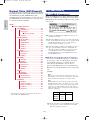
ª
A/D INPUT L/MONO and
R Jacks (A/D INPUT on the EX7)
Line and microphone sampling
sources can be connected to these
jacks. Line or microphone input
sensitivity is switched via the
“line/mic” parameter in the Sample
mode REC display (page 176), and
fine input sensitivity adjustment
can be carried out via the A/D
GAIN control on the control panel.
➡
See page 70 for more
information.
•
INDIVIDUAL OUTPUT 1 and
2 Jacks (EX5 and EX5R only)
In addition to the stereo OUTPUT
L/MONO and R jacks, the EX5 and EX5R
initially have two individual outputs: the
INDIVIDUAL OUTPUT 1 and 2 jacks.
Individual “parts” of a performance setup
can be assigned to different individual
outputs via the PERFORMANCE EDIT
mode PART display (see page 164). Four
individual outputs can be added to the
EX5, EX5R, and EX7 by installing the
optional EXIDO1 Individual Output
Board (page 19.)
§
[POWER] Switch
Press to turn power ON
or OFF. The EX5 and
EX7 power switch is
located on the rear panel
near the AC power cord
socket. The EX5R power
switch is located on the
front panel.
‚
MIDI IN, OUT and THRU Connectors
The MIDI IN connectors receive data from an external sequencer or
other MIDI device which is to control or transmit data to the EX. The
MIDI THRU connector simply re-transmits the data received at the MIDI
IN connector, allowing convenient chaining of MIDI devices. The MIDI
OUT connectors transmit data corresponding to all EX performance and
playback operations.
The EX5 is equipped with two sets of MIDI terminals: MIDI A and MIDI
B. The MIDI A group includes MIDI IN, OUT, and THRU terminals,
while the MIDI B group only has MIDI IN and OUT terminals.
➡
See page 22 for more information.
¶
AC Power Cord Socket
Be sure the plug the AC power cord
into this socket before plugging the
power cord into an AC outlet.
Use only the AC power cord
supplied with the EX5, EX5R, or
EX7. If the supplied cord is lost or
damaged ands needs to be replaced,
contact your Yamaha dealer. The
use of an inappropriate replacement
can pose a fire and shock hazard!
§ ¶
‚
fifl
›‡‹¤⁄ª
* • is not available on EX7.
Rear Panel
Intro/E/qx 5/21/98 11:27 AM Page 14

15
Introductory
Section
AC INLET
CAUTION
ATTENTION
WARNING
RISQUE DE CHOC ELECTRIQUE NE PAS OUVRIR.
TO REDUCE THE RISK OF FIRE OR ELECTRIC SHOCK,
DO NOT EXPOSE THIS PRODUCT TO RAIN OR MOISTURE.
MIDI
OUTTHRU IN
INDIVIDUAL OUTPUT
65 43
DIGITAL OUTPUT
WORD CLOCK IN
AES EBU
INDIVIDUAL OUTPUT
21
OUTPUT
R
L MONO
VOICE PERFORM SONG PATTERN SA MPLE
JOB
LMONO R
BREATH PHONES
VOLUME
AD
INPUT
A D GAIN
STORE UTILIT Y
DISK
SC2
SC1
EDIT
COMPARE
KEYMAP BYPASS
ARPEG KNOB
CURSOR
DATA
TOP
REC STOP PLAY
POWER
REW F WD
ON OFF
DEC NO INC YES
SPACE
ABC
0
123
456
789
ENTER
DEF GHI JKL
MNO
PQR
STU
VWX YZ
INDIVIDUAL OUTPUT
INDIVIDUAL OUTPUT
A/D
INPUT
6543 21
R L MONO
OUTPUT
R L MONO
FOOT
SWITCH
FOOT
CONTROLLER
FOOT
VOLUME
SUSTAIN
DIGITAL OUTPUT WORD CLOCK IN
AES EBU
SCSI
MIDI B MIDI A
OUT IN OUTTHRU IN
BREATH PHONES
EX5R
Front
Rear
⁄
FOOT SWITCH
Jack
(EX5 and EX7 only)
An optional Yamaha
FC4 or FC5 footswitch
can be connected to
this jack to control of a
range of on/off type
functions: sustain,
sotenuto, portamento,
and others.
➡
See page 17 for more
information.
¤
SUSTAIN Jack
(EX5 and EX7
only)
An optional
Yamaha FC4 or
FC5 footswitch
can be connected
here for sustain
control.
‹
FOOT
CONTROLLER
Jack
(EX5 and EX7 only)
This jack accepts a
Yamaha FC7 Foot
Controller which can
be used to control any
of the EX controller
parameters.
➡
See page 17 for
more information.
›
FOOT VOLUME
Jack
(EX5 and EX7 only)
A Yamaha FC7 Foot
Controller can be
plugged in here for
convenient foot
volume or expression
control.
‡
OUTPUT L/MONO and R Jacks
These are the main stereo outputs from
the EX5, EX5R, and EX7. Be sure to
connect both outputs to the appropriate
channels of a stereo sound system in order
to appreciate the full quality of the EX
sound and effects. Connect only the
L/MONO jack when connecting to a mono
sound system.
fl
PHONES Jack
Accepts a standard pair of
stereo headphones (1/4"
stereo phone plug) for
headphone monitoring of
the EX sound without the
need for external
amplification equipment.
The EX5R PHONES jack
is on the front panel.
fi
Breath
Controller Jack
Plug an optional
Yamaha BC3 Breath
Controller in here for
expressive breath
control capability.
➡
See page 56 for
more information.
¶
• ‡‚
߻
§
fi
* ⁄, ¤, ‹ and › are not available on EX5R.
Intro/E/qx 5/21/98 11:27 AM Page 15

16
Introductory
Section
Setting Up
The EX5 or EX7 can be used virtually on its own — with a pair of headphones or a simple
instrument amplifier — or it can be the core of complex and powerful music production
system. Naturally, the EX5R Tone Generator will require an external MIDI keyboard or other
controller.
Power Supply
Before making any other connections the “female” end of the AC power cord supplied with the EX5,
EX5R, and EX7 should be firmly plugged into the rear-panel AC cord socket. Ideally the power cord
should then be plugged into a convenient AC outlet after you've made all other necessary connections
and placed the EX5, EX5R, or EX7 in the position in which it will be used. Always make sure that the
POWER switch is in the OFF (extended) position before plugging the power cord in an AC outlet.
WARNING!
Make sure your EX5, EX5R, or EX7 is rated for the AC voltage supplied in the area in which it is to be
used (as listed on the rear panel). Connecting the unit to the wrong AC supply can cause serious damage to
the internal circuitry and may even pose a shock hazard!
Use only the AC power cord supplied with the EX5, EX5R, or EX7. If the supplied cord is lost or damaged
ands needs to be replaced, contact your Yamaha dealer. The use of an inappropriate replacement can pose a
fire and shock hazard!
The type of AC power cord provided with the EX5, EX5R, or EX7 may be different depending on the
country in which it is purchased (a third prong may be provided for grounding purposes). Improper
connection of the grounding conductor can create the risk of electrical shock. Do NOT modify the plug
provided with the EX5/EX5R/EX7. If the plug will not fit the outlet, have a proper outlet installed by a
qualified electrician. Do not use a plug adapter which defeats the grounding conductor.
AC Power Cord
EX5/7, EX5R
Rear Panel
Basic/E/qx 5/21/98 11:21 AM Page 16

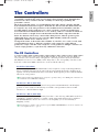
External Controllers
In addition to the many realtime controllers provided on the EX5 and EX7 panel (the PITCH wheel,
MODULATION 1 wheel, MODULATION 2 wheel and Ribbon Controller), plus the six Controller
Knobs provided on the EX5, EX5R and EX7, a number of additional controllers can be plugged into
the appropriate rear-panel jacks as required.
■ Foot Switches (EX5 and EX7)
At the very least you’ll probably want to plug a footswitch into the SUSTAIN jack for piano-type
sustain control. You might also want to plug a second footswitch into the FOOTSWITCH jack to
control other on/off type functions such as sostenuto, portamento, or arpeggio hold for the
sophisticated automatic arpeggiator feature. Footswitch functions are assigned via the UTILITY
mode, as described on page 275.
■ Foot Controllers (EX5 and EX7)
The EX5 and EX7 have jacks for two optional Yamaha FC7 Foot Controller units: FOOT VOLUME
and FOOT CONTROLLER. An FC7 plugged into the FOOT VOLUME jack can be used (as its
name implies) for main volume or expression control. The desired FOOT VOLUME function can
be selected via the UTILITY mode Controller display, as described on page 275. An FC7 plugged
into the FOOT CONTROLLER jack can be assigned for continuous realtime control of a wide
range of parameters (pages 104 and 163).
For more information on Foot Controller setup and operation, see the instructions packed with the supplied
FC7 Foot Controller.
■ Breath Controller
A Breath Controller can be an essential expressive tool for realistic expression with wind-
instrument type voices and unprecedented expressive control with other voices. Plug an optional
BC3 Breath Controller into the BREATH jack. The Breath Controller is ideal for controlling
parameters that would normally be affected by a wind player's breath: dynamics, timbre, pitch, and
others.
For more information on Breath Controller setup and operation, see the instructions packed with the optional
BC3 Breath Controller.
17
Introductory
Section
Basic/E/qx 5/21/98 11:21 AM Page 17

18
Introductory
Section
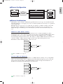
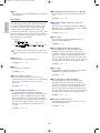
Audio Connections
■ Headphones
For private listening and practice headphones are ideal. You don't have to hook up and complete
sound system, and you won't disturb the neighbors no matter how loud or late you play.
Recommended Yamaha headphones for EX monitoring are the HPE-170, HPE-160, or HPE-150
Stereo Headphones. Any standard pair of stereo headphones with a 1/4" stereo phone plug can be
used.
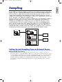
■ Instrument Amplifier or Stereo Sound System
The EX voices and effects are designed to sound their best in stereo, so you should always use a
stereo sound system to appreciate the full impact of the EX voices and expressive features. The
OUTPUT L/MONO and R jacks can be connected directly to musical instrument amplifiers
designed for keyboard use, or to the line inputs of a mixing console. It is also possible to connect
the outputs directly to the inputs of a multitrack or stereo tape recorder. When connecting to a
mono sound system be sure to use only the OUTPUT L/MONO jack.
Make sure that both the EX and your sound system are turned OFF when making connections.
MUSIC SYNTHESIZER
REALTIME CONTROL
EXTENDED SYNTHESIS
EX5/7
Headphones
EX5R
PHONES
OUTPUT L /
MONO jack
R
Amplified Speaker L Amplified Speaker R
Headphones
PHONES
OUTPUT L /
MONO jack
R
Amplified Speaker L Amplified Speaker R
MUSIC SYNTHESIZER
REALTIME CONTROL
EXTENDED SYNTHESIS
1 2 3 4 5 6
Basic/E/qx 5/21/98 11:21 AM Page 18

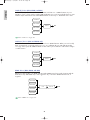
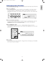
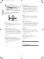
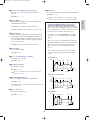
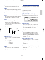
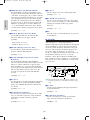
■ Mixing Console
In addition to the stereo OUTPUT L/MONO and R jacks, the EX5 and EX5R initially have two
individual outputs: the INDIVIDUAL OUTPUT 1 and 2 jacks. An additional four individual
outputs (3 through 6) can be added by installing the optional EXIDO1 Individual Output Board.
The stereo and individual outputs can be fed to separate channels of a mixing console for
individual processing. Individual “parts” of a performance setup can be assigned to different
individual outputs via the PERFORMANCE EDIT mode PART display (see page 164).
See page 278 for details on installation of the EXIDO1 Individual Output Board.
The EXIDO1 Individual Output Board and EXDGO1 Digital Output Board use the same option slot, so only
one can be installed at a time.
1 2 3 4 5 6 7 8 9 10 11 12 13 14 15 16 L R
EX5
or
EX5R
Mixer
Speakers
Amp
L
OUTPUT L
OUTPUT
L/MONO
R
R
R
INDIVIDUAL
OUTPUT
123456
1 2 3 4 5 6 7 8
MUSIC SYNTHESIZER
REALTIME CONTROL
EXTENDED SYNTHESIS
1 2 3 4 5 6
MUSIC SYNTHESIZER
REALTIME CONTROL
EXTENDED SYNTHESIS
EXIDO1
MUSIC SYNTHESIZER
REALTIME CONTROL
EXTENDED SYNTHESIS
1 2 3 4 5 6 7 8 9 10 11 12 13 14 15 16 L R
HeadphoneHeadphone
Mixer
Speakers
Amp
L
OUTPUT L
OUTPUT
L/MONO
R
R
R
INDIVIDUAL
OUTPUT
EXIDO1
PHONESPHONES
1234
1 2 3 4 5 6
EX7
1 2 3 4 5 6 7 8 9 10 11 12 13 14 15 16 L R
MUSIC SYNTHESIZER
REALTIME CONTROL
EXTENDED SYNTHESIS
1 2 3 4 5 6
Headphones
EX5
or
EX5R
EX7
Mixer
Speakers
Amp
L
OUTPUT L
R
OUTPUT
L/MONO
PHONES PHONES
INDIVIDUAL
OUTPUT 1
INDIVIDUAL
OUTPUT 2
R
R
1 2 3 4 5 6 7 8 9 10 11 12 13 14 15 16 L R
MUSIC SYNTHESIZER
REALTIME CONTROL
EXTENDED SYNTHESIS
Headphones
Mixer
Speakers
AMP
L
OUTPUT L
R
OUTPUT
L/MONO
R
R
MUSIC SYNTHESIZER
REALTIME CONTROL
EXTENDED SYNTHESIS
19
Introductory
Section
Basic/E/qx 5/21/98 11:21 AM Page 19

20
Introductory
Section
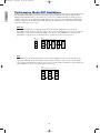
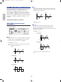
■ Digital Audio (Option)
The optional EXDGO1 Digital Output Board provides an AES/EBU-format digital output which
can be directly connected to an external digital recorder, mixing console, or other digital processing
equipment. This allows the EX sound to be recorded or processed with maximum quality. The
EXDGO1 Digital Output Board also includes a WORD CLOCK IN connector for precise digital
audio synchronization with the external digital devices.
See page 278 for details on installation of the EXDGO1 Digital Output Board.
The EXDGO1 Digital Output Board and EXIDO1 Individual Output Board use the same option slot, so only
one can be installed at a time.
When connecting the EXDGO1 (Digital Output AES/EBU [XLR] jack) and an external audio device, use the
XLR cable with the impedance characteristics, 110 Ω.
When receiving word clock from an external audio device, you are required to connect the EXDGO1 (Word
Clock In [BNC] jack) and the external audio device. In this case, use the BNC connector/coaxial cable with
the impedance characteristics, 75 Ω.
AC INLET
DAT
EX5R
DAT
O3D
INDIVIDUAL OUTPUT
6543
DIGITAL OUTPUT WORD CLOCK IN
AES EBU
DAT
EX5/7
DAT
O3D
INDIVIDUAL OUTPUT
6543
DIGITAL OUTPUT WORD CLOCK IN
AES EBU
Basic/E/qx 5/21/98 11:21 AM Page 20
La pagina si sta caricando...
La pagina si sta caricando...
La pagina si sta caricando...
La pagina si sta caricando...
La pagina si sta caricando...
La pagina si sta caricando...
La pagina si sta caricando...
La pagina si sta caricando...
La pagina si sta caricando...
La pagina si sta caricando...
La pagina si sta caricando...
La pagina si sta caricando...
La pagina si sta caricando...
La pagina si sta caricando...
La pagina si sta caricando...
La pagina si sta caricando...
La pagina si sta caricando...
La pagina si sta caricando...
La pagina si sta caricando...
La pagina si sta caricando...
La pagina si sta caricando...
La pagina si sta caricando...
La pagina si sta caricando...
La pagina si sta caricando...
La pagina si sta caricando...
La pagina si sta caricando...
La pagina si sta caricando...
La pagina si sta caricando...
La pagina si sta caricando...
La pagina si sta caricando...
La pagina si sta caricando...
La pagina si sta caricando...
La pagina si sta caricando...
La pagina si sta caricando...
La pagina si sta caricando...
La pagina si sta caricando...
La pagina si sta caricando...
La pagina si sta caricando...
La pagina si sta caricando...
La pagina si sta caricando...
La pagina si sta caricando...
La pagina si sta caricando...
La pagina si sta caricando...
La pagina si sta caricando...
La pagina si sta caricando...
La pagina si sta caricando...
La pagina si sta caricando...
La pagina si sta caricando...
La pagina si sta caricando...
La pagina si sta caricando...
La pagina si sta caricando...
La pagina si sta caricando...
La pagina si sta caricando...
La pagina si sta caricando...
La pagina si sta caricando...
La pagina si sta caricando...
La pagina si sta caricando...
La pagina si sta caricando...
La pagina si sta caricando...
La pagina si sta caricando...
La pagina si sta caricando...
La pagina si sta caricando...
La pagina si sta caricando...
La pagina si sta caricando...
La pagina si sta caricando...
La pagina si sta caricando...
La pagina si sta caricando...
La pagina si sta caricando...
La pagina si sta caricando...
La pagina si sta caricando...
La pagina si sta caricando...
La pagina si sta caricando...
La pagina si sta caricando...
La pagina si sta caricando...
La pagina si sta caricando...
La pagina si sta caricando...
La pagina si sta caricando...
La pagina si sta caricando...
La pagina si sta caricando...
La pagina si sta caricando...
La pagina si sta caricando...
La pagina si sta caricando...
La pagina si sta caricando...
La pagina si sta caricando...
La pagina si sta caricando...
La pagina si sta caricando...
La pagina si sta caricando...
La pagina si sta caricando...
La pagina si sta caricando...
La pagina si sta caricando...
La pagina si sta caricando...
La pagina si sta caricando...
La pagina si sta caricando...
La pagina si sta caricando...
La pagina si sta caricando...
La pagina si sta caricando...
La pagina si sta caricando...
La pagina si sta caricando...
La pagina si sta caricando...
La pagina si sta caricando...
La pagina si sta caricando...
La pagina si sta caricando...
La pagina si sta caricando...
La pagina si sta caricando...
La pagina si sta caricando...
La pagina si sta caricando...
La pagina si sta caricando...
La pagina si sta caricando...
La pagina si sta caricando...
La pagina si sta caricando...
La pagina si sta caricando...
La pagina si sta caricando...
La pagina si sta caricando...
La pagina si sta caricando...
La pagina si sta caricando...
La pagina si sta caricando...
La pagina si sta caricando...
La pagina si sta caricando...
La pagina si sta caricando...
La pagina si sta caricando...
La pagina si sta caricando...
La pagina si sta caricando...
La pagina si sta caricando...
La pagina si sta caricando...
La pagina si sta caricando...
La pagina si sta caricando...
La pagina si sta caricando...
La pagina si sta caricando...
La pagina si sta caricando...
La pagina si sta caricando...
La pagina si sta caricando...
La pagina si sta caricando...
La pagina si sta caricando...
La pagina si sta caricando...
La pagina si sta caricando...
La pagina si sta caricando...
La pagina si sta caricando...
La pagina si sta caricando...
La pagina si sta caricando...
La pagina si sta caricando...
La pagina si sta caricando...
La pagina si sta caricando...
La pagina si sta caricando...
La pagina si sta caricando...
La pagina si sta caricando...
La pagina si sta caricando...
La pagina si sta caricando...
La pagina si sta caricando...
La pagina si sta caricando...
La pagina si sta caricando...
La pagina si sta caricando...
La pagina si sta caricando...
La pagina si sta caricando...
La pagina si sta caricando...
La pagina si sta caricando...
La pagina si sta caricando...
La pagina si sta caricando...
La pagina si sta caricando...
La pagina si sta caricando...
La pagina si sta caricando...
La pagina si sta caricando...
La pagina si sta caricando...
La pagina si sta caricando...
La pagina si sta caricando...
La pagina si sta caricando...
La pagina si sta caricando...
La pagina si sta caricando...
La pagina si sta caricando...
La pagina si sta caricando...
La pagina si sta caricando...
La pagina si sta caricando...
La pagina si sta caricando...
La pagina si sta caricando...
La pagina si sta caricando...
La pagina si sta caricando...
La pagina si sta caricando...
La pagina si sta caricando...
La pagina si sta caricando...
La pagina si sta caricando...
La pagina si sta caricando...
La pagina si sta caricando...
La pagina si sta caricando...
La pagina si sta caricando...
La pagina si sta caricando...
La pagina si sta caricando...
La pagina si sta caricando...
La pagina si sta caricando...
La pagina si sta caricando...
La pagina si sta caricando...
La pagina si sta caricando...
La pagina si sta caricando...
La pagina si sta caricando...
La pagina si sta caricando...
La pagina si sta caricando...
La pagina si sta caricando...
La pagina si sta caricando...
La pagina si sta caricando...
La pagina si sta caricando...
La pagina si sta caricando...
La pagina si sta caricando...
La pagina si sta caricando...
La pagina si sta caricando...
La pagina si sta caricando...
La pagina si sta caricando...
La pagina si sta caricando...
La pagina si sta caricando...
La pagina si sta caricando...
La pagina si sta caricando...
La pagina si sta caricando...
La pagina si sta caricando...
La pagina si sta caricando...
La pagina si sta caricando...
La pagina si sta caricando...
La pagina si sta caricando...
La pagina si sta caricando...
La pagina si sta caricando...
La pagina si sta caricando...
La pagina si sta caricando...
La pagina si sta caricando...
La pagina si sta caricando...
La pagina si sta caricando...
La pagina si sta caricando...
La pagina si sta caricando...
La pagina si sta caricando...
La pagina si sta caricando...
La pagina si sta caricando...
La pagina si sta caricando...
La pagina si sta caricando...
La pagina si sta caricando...
La pagina si sta caricando...
La pagina si sta caricando...
La pagina si sta caricando...
La pagina si sta caricando...
La pagina si sta caricando...
La pagina si sta caricando...
La pagina si sta caricando...
La pagina si sta caricando...
La pagina si sta caricando...
La pagina si sta caricando...
La pagina si sta caricando...
La pagina si sta caricando...
La pagina si sta caricando...
La pagina si sta caricando...
La pagina si sta caricando...
La pagina si sta caricando...
La pagina si sta caricando...
La pagina si sta caricando...
La pagina si sta caricando...
La pagina si sta caricando...
La pagina si sta caricando...
La pagina si sta caricando...
La pagina si sta caricando...
La pagina si sta caricando...
La pagina si sta caricando...
La pagina si sta caricando...
La pagina si sta caricando...
La pagina si sta caricando...
La pagina si sta caricando...
La pagina si sta caricando...
La pagina si sta caricando...
La pagina si sta caricando...
La pagina si sta caricando...
La pagina si sta caricando...
La pagina si sta caricando...
La pagina si sta caricando...
La pagina si sta caricando...
La pagina si sta caricando...
La pagina si sta caricando...
La pagina si sta caricando...
La pagina si sta caricando...
La pagina si sta caricando...
La pagina si sta caricando...
La pagina si sta caricando...
La pagina si sta caricando...
La pagina si sta caricando...
La pagina si sta caricando...
La pagina si sta caricando...
La pagina si sta caricando...
La pagina si sta caricando...
La pagina si sta caricando...
La pagina si sta caricando...
La pagina si sta caricando...
La pagina si sta caricando...
La pagina si sta caricando...
-
 1
1
-
 2
2
-
 3
3
-
 4
4
-
 5
5
-
 6
6
-
 7
7
-
 8
8
-
 9
9
-
 10
10
-
 11
11
-
 12
12
-
 13
13
-
 14
14
-
 15
15
-
 16
16
-
 17
17
-
 18
18
-
 19
19
-
 20
20
-
 21
21
-
 22
22
-
 23
23
-
 24
24
-
 25
25
-
 26
26
-
 27
27
-
 28
28
-
 29
29
-
 30
30
-
 31
31
-
 32
32
-
 33
33
-
 34
34
-
 35
35
-
 36
36
-
 37
37
-
 38
38
-
 39
39
-
 40
40
-
 41
41
-
 42
42
-
 43
43
-
 44
44
-
 45
45
-
 46
46
-
 47
47
-
 48
48
-
 49
49
-
 50
50
-
 51
51
-
 52
52
-
 53
53
-
 54
54
-
 55
55
-
 56
56
-
 57
57
-
 58
58
-
 59
59
-
 60
60
-
 61
61
-
 62
62
-
 63
63
-
 64
64
-
 65
65
-
 66
66
-
 67
67
-
 68
68
-
 69
69
-
 70
70
-
 71
71
-
 72
72
-
 73
73
-
 74
74
-
 75
75
-
 76
76
-
 77
77
-
 78
78
-
 79
79
-
 80
80
-
 81
81
-
 82
82
-
 83
83
-
 84
84
-
 85
85
-
 86
86
-
 87
87
-
 88
88
-
 89
89
-
 90
90
-
 91
91
-
 92
92
-
 93
93
-
 94
94
-
 95
95
-
 96
96
-
 97
97
-
 98
98
-
 99
99
-
 100
100
-
 101
101
-
 102
102
-
 103
103
-
 104
104
-
 105
105
-
 106
106
-
 107
107
-
 108
108
-
 109
109
-
 110
110
-
 111
111
-
 112
112
-
 113
113
-
 114
114
-
 115
115
-
 116
116
-
 117
117
-
 118
118
-
 119
119
-
 120
120
-
 121
121
-
 122
122
-
 123
123
-
 124
124
-
 125
125
-
 126
126
-
 127
127
-
 128
128
-
 129
129
-
 130
130
-
 131
131
-
 132
132
-
 133
133
-
 134
134
-
 135
135
-
 136
136
-
 137
137
-
 138
138
-
 139
139
-
 140
140
-
 141
141
-
 142
142
-
 143
143
-
 144
144
-
 145
145
-
 146
146
-
 147
147
-
 148
148
-
 149
149
-
 150
150
-
 151
151
-
 152
152
-
 153
153
-
 154
154
-
 155
155
-
 156
156
-
 157
157
-
 158
158
-
 159
159
-
 160
160
-
 161
161
-
 162
162
-
 163
163
-
 164
164
-
 165
165
-
 166
166
-
 167
167
-
 168
168
-
 169
169
-
 170
170
-
 171
171
-
 172
172
-
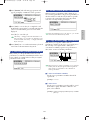 173
173
-
 174
174
-
 175
175
-
 176
176
-
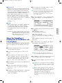 177
177
-
 178
178
-
 179
179
-
 180
180
-
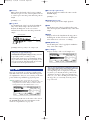 181
181
-
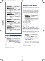 182
182
-
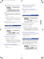 183
183
-
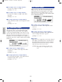 184
184
-
 185
185
-
 186
186
-
 187
187
-
 188
188
-
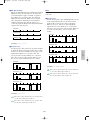 189
189
-
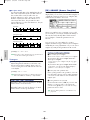 190
190
-
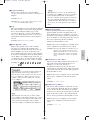 191
191
-
 192
192
-
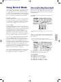 193
193
-
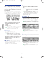 194
194
-
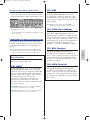 195
195
-
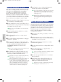 196
196
-
 197
197
-
 198
198
-
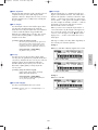 199
199
-
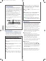 200
200
-
 201
201
-
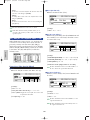 202
202
-
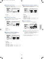 203
203
-
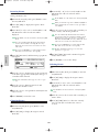 204
204
-
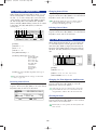 205
205
-
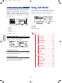 206
206
-
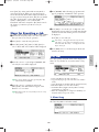 207
207
-
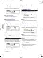 208
208
-
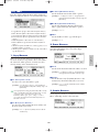 209
209
-
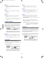 210
210
-
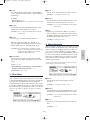 211
211
-
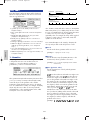 212
212
-
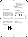 213
213
-
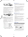 214
214
-
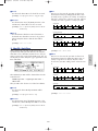 215
215
-
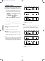 216
216
-
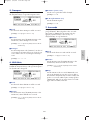 217
217
-
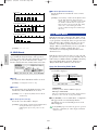 218
218
-
 219
219
-
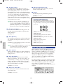 220
220
-
 221
221
-
 222
222
-
 223
223
-
 224
224
-
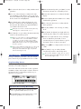 225
225
-
 226
226
-
 227
227
-
 228
228
-
 229
229
-
 230
230
-
 231
231
-
 232
232
-
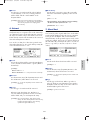 233
233
-
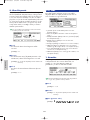 234
234
-
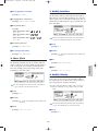 235
235
-
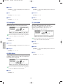 236
236
-
 237
237
-
 238
238
-
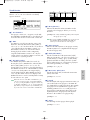 239
239
-
 240
240
-
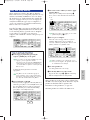 241
241
-
 242
242
-
 243
243
-
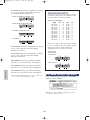 244
244
-
 245
245
-
 246
246
-
 247
247
-
 248
248
-
 249
249
-
 250
250
-
 251
251
-
 252
252
-
 253
253
-
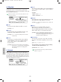 254
254
-
 255
255
-
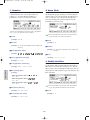 256
256
-
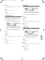 257
257
-
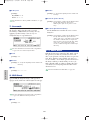 258
258
-
 259
259
-
 260
260
-
 261
261
-
 262
262
-
 263
263
-
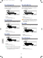 264
264
-
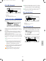 265
265
-
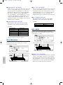 266
266
-
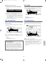 267
267
-
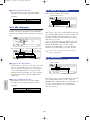 268
268
-
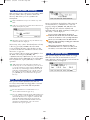 269
269
-
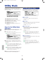 270
270
-
 271
271
-
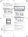 272
272
-
 273
273
-
 274
274
-
 275
275
-
 276
276
-
 277
277
-
 278
278
-
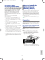 279
279
-
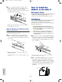 280
280
-
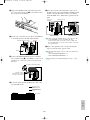 281
281
-
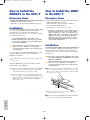 282
282
-
 283
283
-
 284
284
-
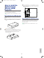 285
285
-
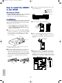 286
286
-
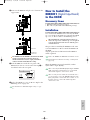 287
287
-
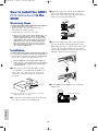 288
288
-
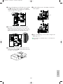 289
289
-
 290
290
-
 291
291
-
 292
292
-
 293
293
-
 294
294
-
 295
295
-
 296
296
-
 297
297
-
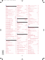 298
298
-
 299
299
-
 300
300
-
 301
301
-
 302
302
-
 303
303
-
 304
304


Yamaha EX5 Manuale utente
- Categoria
- Sintetizzatore
- Tipo
- Manuale utente
in altre lingue
- English: Yamaha EX5 User manual
- français: Yamaha EX5 Manuel utilisateur
- español: Yamaha EX5 Manual de usuario
- Deutsch: Yamaha EX5 Benutzerhandbuch
- русский: Yamaha EX5 Руководство пользователя
- Nederlands: Yamaha EX5 Handleiding
- português: Yamaha EX5 Manual do usuário
- dansk: Yamaha EX5 Brugermanual
- čeština: Yamaha EX5 Uživatelský manuál
- polski: Yamaha EX5 Instrukcja obsługi
- svenska: Yamaha EX5 Användarmanual
- Türkçe: Yamaha EX5 Kullanım kılavuzu
- suomi: Yamaha EX5 Ohjekirja
- română: Yamaha EX5 Manual de utilizare
Documenti correlati
-
Yamaha Version2 Manuale del proprietario
-
Yamaha QY700 Manuale utente
-
-
-
-
Yamaha PLG150-AN Manuale del proprietario
-
-
-
-
Altri documenti
-
Fender G-DEC 30 Manuale utente
-
Korg POLY-800II Manuale del proprietario
-
Akai Professional Tom Cat Manuale utente
-
Steinberg Padshop Manuale utente
-
-
Aim-TTI TGF4042 Guida Rapida
-
-
Behringer JT-4000 MICRO Guida Rapida
-
Hughes & Kettner Grand Meister 36 Manuale utente
-