
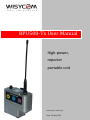
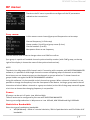
RPU500-Tx User Manual
High-power,
reporter
portable unit
Rev.04 (ref. FW v1.4)
Date: 24 May 2021

RPU500-Tx User Manual
2
SAFETY INSTRUCTION
Read this safety instruction and the manual first
Follow all instructions and information.
Do not lose this manual.
The unit is designed for Professional Use only
Do not use this apparatus under the rain or near the water.
Do not install the apparatus near heaters or in hot environments, do not use outside the
operating temperature range.
Do not open the apparatus, only qualified service technician are enabled to operate on it. The
apparatus needs servicing when it is not properly working or is damaged by liquids, moisture
or other objects are fallen in the apparatus.
Use only accessories or replacement parts authorized or specified by the manufacturer.
Clean the apparatus only with dry cloths, do not use liquids.
Report the serial number and the purchasing date in front of the manual. It is needed to have
proper replacement parts or accessories from the manufacturer.
When replacement parts are needed, use only replacement parts authorized from the
manufacturer. Substitution with not authorized parts could result in electric shock, hazards or
fire.
Keep attention on all the labels with warnings or hazards on the apparatus.

RPU500-Tx User Manual
3
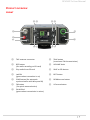
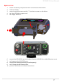
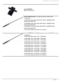
PRODUCT OVERVIEW
FRONT
❶
TNC antenna connector
❽
TALK button
(to activate TALK transmission)
❷
REC button
(for audio recording on SD card)
❾
VOLUME knob
❸
Play audio from SD card
❿
SAVE or SEL button
❹
Led ON
(green when transmitter is on)
⓫
EXIT button
❺
SYNC button (for automatic
synchronization with Wisycom RX)
⓬
DOWN arrow button
❻
FN button
(for quick menu selection)
⓭
UP arrow button
❼
ON AIR led
(green when transmission is active)
❶
❷
❸
❹
❺
❿
⓫
❻
❼
⓬
⓭
❽
❾

RPU500-Tx User Manual
4
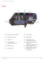
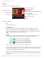
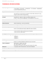
REAR
❶
battery compartment latch
❼
Lazy 2 button*
❷
battery compartment
❽
Lazy 3 button*
❸
SD card slot
❾
XLR-3pin connector
for MIC/LINE audio input
❹
USB-C connector
(for power and control)
❿
Hirose 4-pin power supply
connector
10-18V (pin1:GND, pin4:+Vdc)
❺
ON/OFF switch
⓫
waterproof jack 3.5mm
(audio output or Aux input)
❻
Lazy 1 button*
⓬
waterproof jack 3.5mm
(audio output)
❶
❾
❿
❻
❼
❽
⓬
⓫
❸
❹
❺
❷

RPU500-Tx User Manual
5
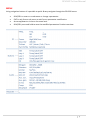
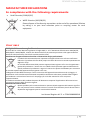
QUICK SETUP
1. unlatch the battery compartment latch at the bottom of the device
2. insert the battery
3. move the wireless power switch in “I” position to power on the device
4. the front LED lights up green and
5. the display switch on
6. connect the XLR MIC (If required enables Phantom 12V/48V thru Audio>Phantom menu)
7. set frequency thru RF>FREQ menu
8. connect the antenna (according to set frequency)
9. set RF Power thru RF>Power menu
10. push the TALK button to activate transmission
❹
❺
❶
❷
❸
❻

RPU500-Tx User Manual
6
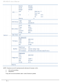
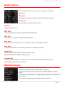
DISPLAY
This is the first menu displayed after power up
Status of Transmission:
OFF:
RF transmission is OFF
ST-BY [Stand-by]:
It is the status of the transmitter after the power on when “TX Start” menu is set to
MUTE. The transmitter sends the carrier with an auxiliary tone (@28kHz) without the
audio (The TX occupies the channel) MRK980 receiver puts in MUTE the audio output
A X icon is showed to indicate that the audio is muted
ON-AIR:
RF transmission is active with audio and an auxiliary sub-tone. According to the pushed
button the auxiliary sub-tone is different and the display show a different icon:
o T when Talk button is pushed (sub-tone@ ̴33kHz)
o 1 when Lazy 1 button is pushed (sub-tone@ 32687 Hz*)
o 2 when Lazy 2 button is pushed (sub-tone@ 32869 Hz*)
o 3 when Lazy 3 button is pushed (sub-tone@ 33013 Hz*)
*Standard Wisycom sub-tone. Other sub-tones can be configured in Wisycom factory
In the Talk mode, just press the Talk button once and the transmission remains active until
the button is pressed again. In Lazy mode, on the other hand, it is necessary to hold down
the Lazy buttons to keep the transmission active.
Wisycom receiver MRK980 detects the sub-tones and pass this information to the mixer
(via Ethernet / Ember + protocol). From the mixer it is therefore possible to configure the
audio routing.
Name of transmitter
Level of RF Power
Compander
Level of Battery
% and time (hours :minutes)
Time
Level of audio input
Frequency
Group & Channel
Modulation Bandwidth (Wide/Narrow)
Status of Transmission

RPU500-Tx User Manual
7
MENU
Using navigation buttons it is possible to quick & easy navigate through the RPU500 menu:
SAVE/SEL to enter on a sub-menu or change a parameter
EXIT to exit from a sub-menu or exit from a parameter modification
Arrow up/down to circle on the same level
SAVE/SEL press and hold to save the modified parameters Product overview

RPU500-Tx User Manual
8
NOTE: Features not still implemented (reference firmware v1.4):
SD card recording
Bluetooth
They will soon be available with a next firmware update.

RPU500-Tx User Manual
9
RF menu:
Thanks to the RF menu is possible to configure all the RF parameters
related to the transmission.
Freq. menu:
In this menu current channel/group and frequencies can be setup.
Channel frequency (in 5kHz step)
Group number (1 to 40) and group name (8 char.)
Channel number (0 to 60)
Max power allows at set frequency
Use the selector and arrows to change values and SAVE to confirm.
Sync group is a quick self-settable channel synchronized by receiver (with SYNC group, on the top
right of the display is shown the name of the synchronized receiver).
NOTE:
The device has 40 groups of 60 channels each. Connecting with computer with WISYCOM MANAGER
software, it is possible to hide single channels or even complete groups of channels: once hidden
those items are not shown anymore on the channels or groups selection. To show channels or
groups hidden use again the WISYCOM MANAGER software.
Using this software it is also possible to lock channels or groups. When a channel is locked, it is not
possible to change the frequency from the front panel of the device. Locking a group means that all
channels are locked. When a channel or a group are locked, at the left of the group name will appear
a lock icon as shown thus changing frequency is not possible.
Power:
RF power can be set in 3 levels: Low, Mid and High.
These 3 levels can be configured by the user with WISYCOM MANAGER.
Factory pre-configured values in Wisycom are: Low 100mW, Mid 300mW and High 1000mW.
Modulation Bandwidth:
Select the type of modulation bandwidth:
WB (Wideband) : 40kHz of nominal deviation, 56kH of peak deviation and 50÷21kHz of AF
bandwidth

RPU500-Tx User Manual
10
NB (Narrowband) : 35kHz of nominal deviation, 25kH of peak deviation and 50÷17kHz of
AF bandwidth
TX Start:
It is possible to select 3 startup modes:
OFF: RF output remains OFF. To activate the transmission, select the Talk or Lazy buttons.
MUTE: activates a specific tone at 28kHz which engages the channel (no audio) which is
recognized by the MRK980 receiver and mutes the audio output
TALK: immediately activates transmission (send audio and tone at 33kHz). A lock icon
appears on the display to inform the user that Talk and Lazy buttons are locked.
TALK + LAZY: immediately activates transmission (send audio and tone at 33kHz). A lock
icon appears on the display to inform the user that Talk button is locked. The Lazy buttons
(1,2 and 3) are active and follow the settings defined on the “Buttons” menu.
The choice of one of these modes is instantaneous (no need to restart the device)
Pwr profile:
Wisycom pre-configure a Power Profile in the memory of the device which automatically limit the RF
level and/or the frequency ranges according to the county specification.
With NONE Pwr profile, no limit is configured.
Buttons menu:
Buttons menu allows to configure the behavior of the Talk button, Lazy buttons and Function (FN)
button.
Talk and Lazy buttons can be configured in:
OFF: when pressed no action is triggered
Temp: transmission active as long as the button is held down (temporary)
Latch: pressed once activates transmission, pressed again disables transmission
Function (FN) button can be configured in:
OFF: no function
Mic gain: active the “Audio> Mic gain” menu
AUX gain: active the “Audio> AUX gain” menu
In mix: active the “Audio> Input mix” menu

RPU500-Tx User Manual
11
Audio menu:
Thanks to the Audio menu is possible to configure all the audio
parameters.
Mic gain:
To change gain from 0 to 38 dB on MIC/LINE IN audio input port.
Phantom:
To enable phantom power (12V or 48V).
Limiter:
To enable audio limiter.
MIC HPF:
To set audio High Pass Filter (FLAT/60/80/120/170/240 Hz)
MIC LPF:
To set audio Low Pass Filter (20/15/12/10/7/5/4 Hz)
Aux con.:
To set jack 3.5mm audio connector as auxiliary input or as headphone output.
Aux gain:
To adjust audio level on the auxiliary input (from 0 to 40 dB, 2 dB step)
Input mix:
To define audio inputs and mix different audio sources
(MIC/AUX/REC/MIC+AUX/MIC+REC/AUX+REC)
Compander:
To select audio compander. Firmware version v1.0 supports only ENS compander. Other
companders will be available very soon.
Options menu:
Thanks to the Option menu is possible to verify:
- Information of device (Serial, Hw version, Fw version)
- Status of the device (alarms, RF diagnostic, Supply diagnostic, Battery
status)
The Display sub-menu allows to change display parameters like brightness
and timeout.
To set the factory parameters select the Factory submenu.

RPU500-Tx User Manual
12
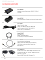
ACCESSORIES AND PARTS
Item: LBP500
Standard Lithium Battery pack 10.80V / 3.35Ah /
36.20Wh
Item: LBC500
Mini Smart Battery Charger with external power supply
Item: CAL1x
Power Cord 2 m. black
CAL11: USA, NEMA 5-15P / IEC 60320 C5
CAL12: Europe, SCHUKO / IEC 60320 C5
CAL13: UK, UK / IEC 60320 C5
Item:CAUSBC1
USB Cable 1m
USB B - USB C Male Black
To monitor/control/power RPU500
Item: CDC34
External power feeding cable
CDC34: hirose 4pin Male/raw wires (50 cm)
CDC34HM: hirose 4pin Male/ hirose 4pin
Male (50 cm)
Item: PSP910-H
AC/DC Power Supply, Switch Mode with Hirose 4 pin
connector (to use one “desktop” apparatus alone)
Input:100 ÷ 240V ac
Ouput:12V@700mA, 8W, Plug type: EU

RPU500-Tx User Manual
13
Item: BCL500
Belt Clip RPU500
Item: AWB500-xxx 1/2 Dipole antenna with BNC
connector:
• AWB500-494: band 470-517 MHZ • AWB500-540:
band 515-563 MHZ
• AWB500-590: band 562-609 MHZ • AWB500-625:
band 609-645 MHZ
• AWB500-670: band 645-696 MHZ • AWB500-950:
band 940-960 MHZ
(*) other frequency bands on request
Item: AWT500-xxx 1/2 Dipole antenna with TNC
connector:
• AWT500-180: band 170 ÷ 188 MHz
• AWT500-197: band 188 ÷ 206 MHz
• AWT500-213: band 206 ÷ 220 MHz
• AWT500-229: band 220 ÷ 238 MHz
• AWT500-458 : band 440 ÷ 480 MHz
• AWT500-494 : band 470 ÷ 517 MHz
• AWT500-540 : band 515 ÷ 563 MHz
• AWT500-590 : band 562 ÷ 609 MHz
• AWT500-625 : band 609 ÷ 645 MHz
• AWT500-670 : band 645 ÷ 696 MHz
• AWT500-950 : band 940 ÷ 960 MHz
(*) other frequency bands on request

RPU500-Tx User Manual
14
TECHNICAL SPECIFICATIONS
Frequency ranges
T1 band (MHz): 170-230 MHz + 450-696 MHz + 715-744 MHz + 940-960 MHz
T2 band (MHz): 170-230 MHz + 440-696 MHz + 715-744 MHz + 940-960 MHz
(*) Japan 160/460 MHz (optional)
Switchable channels
2400 managed in 40 groups ofr 60 frequencies completely user customizable
Frequencies
5 kHz step
The frequencies can be easily PC reprogrammed with USB C, Bluetooth 5 (long
range) or optional UPKmini Programming
Frequency error
< ± 2.5 ppm, in the rated temperature range
RF Power
switchable Low / Medium / High, typ. 100mW / 300mW / 1W
(*) note: in some countries high power can be disabled, for local norm!
Antenna connector
TNC type female (BNC for T1 version)
RF impedance
50 ohm
Modulation
FM mono, wideband or narrowband IFB (SW selectable)
Nominal deviation
±40 kHz (wideband), ± 25 kHz (narrowband)
Peak deviation
±56 kHz (wideband), ± 35 kHz (narrowband)
Spurious emissions
< 2 nW (typical = 0.1 pW)
Noise Reduction system
ENS - Wisycom Extended-Sound Optimized (other on request)
AF bandwidth
50 Hz ÷ 20 KHz (1dB) (Wideband, ARM based, SW switchable)
50 Hz ÷ 15 KHz (1dB) (Narrowband, ARM based, SW switchable)
Audio input connector
1 x XLR3-F type (MIC/Line level) for audio input
1 x Jack 3.5mm for audio input/output (sw selectable)
1 x Jack 3.5mm for audio output
Managing interface
USB C, Bluetooth 5 (long range) or optional UPKmini Programming
Command buttons & signaling
• Pgm
• Talkback 1
• Talkback 2
• Talkback 3
Display
Transflective color display with high visibility in the sun
Power supply
standard battery pack RRC2040 or
External = 10 ÷ 18 Vdc (10W max) with Hirose 4-pin connector
Power consumption
440mA @12V / 5.28W in VHF range
450 ÷ 530 mA @12V in UHF range
depending of the frequency and temperature (display off, 1 Watt)
Battery life
> 5h (power profile & IIP3 trade off) with Lithium RRC2040
Temperature range
-10 ÷ +55 °C
Dimensions
73,1mm x 64,5mm x 21,6mm (H x W x D) with clip
Weight
950g (battery included)

RPU500-Tx User Manual
15
MANUFACTURER DECLARATIONS
In compliance with the following requirements
RoHS Directive (2002/95/EC)
WEEE Directive (2002/96/EC)
Please dispose of the diversity transmitter at the end of its operational lifetime
by taking it to your local collection point or recycling center for such
equipment
ITALY ONLY
Obblighi di informazione agli utilizzatori
ai sensi dell’art. 13 del Decreto Legislativo 25 luglio 2005, n. 151 “Attuazione delle Direttive 2002/95/CE,
2002/96/CE e 2003/108/CE, relative alla riduzione dell’uso di sostanze pericolose nelle apparecchiature
elettriche ed elettroniche, nonché allo smaltimento dei rifiuti”
Smaltimento di apparecchiature elettriche ed elettroniche di tipo professionale
Il simbolo del cassonetto barrato riportato sull’apparecchiatura o sulla sua confezione
indica che il prodotto alla fine della propria vita utile deve essere raccolto separatamente
dagli altri rifiuti.
La raccolta differenziata della presente apparecchiatura giunta a fine vita è organizzata e
gestita dal produttore. L’utente che vorrà disfarsi della presente apparecchiatura dovrà
quindi contattare il produttore e seguire il sistema che questo ha adottato per consentire
la raccolta separata dell’apparecchiatura giunta a fine vita.
L’adeguata raccolta differenziata per l’avvio successivo dell’apparecchiatura dismessa al riciclaggio, al
trattamento e allo smaltimento ambientale compatibile contribuisce ad evitare possibili effetti negativi
sull’ambiente e sulla salute e favorisce il reimpiego e/o riciclo dei materiali di cui è composta
l’apparecchiatura.
Lo smaltimento abusivo del prodotto da parte del detentore comporta l’applicazione delle sanzioni am-
ministrative previste dalla normativa vigente.
Smaltimento batterie usate
Questo prodotto può contenere batterie. Questo simbolo apposto sulle batterie significa
che non possono essere smaltite insieme a normali rifiuti domestici, bensì devono essere
depositate negli appositi punti di raccolta delle batterie.
Iscrizione al Registro A.E.E. n. IT09100000006319

-
 1
1
-
 2
2
-
 3
3
-
 4
4
-
 5
5
-
 6
6
-
 7
7
-
 8
8
-
 9
9
-
 10
10
-
 11
11
-
 12
12
-
 13
13
-
 14
14
-
 15
15
-
 16
16


in altre lingue
- English: WisyCom RPU500 User manual
Documenti correlati
-
WisyCom RPU500 Manuale utente
-
WisyCom CST38 Manuale utente
-
-
-
-
-
-
-
-