
V PLUS series
acve loudspeakers
USER MANUAL
MANUALE D'USO

FCC COMPLIANCE NOTICE
This device complies with part 15 of the FCC rules. Operaon is subject to the following two condions:
(1) This device may not cause harmful interference, and
(2) this device must accept any interference received, including interference that may cause undesired operaon.
CAUTION: Changes or modicaons not expressly approved by the party responsible for compliance could void
the user’s authority to operate the equipment.
NOTE: This equipment has been tested and found to comply with the limits for a Class B digital device, pursuant to
part 15 of the FCC Rules. These limits are designed to provide reasonable protecon against harmful interference in
a residenal installaon. This equipment generates, uses, and can radiate radio frequency energy and, if not installed
and used in accordance with the instrucon manual, may cause harmful interference to radio communicaons.
However, there is no guarantee that interference will not occur in a parcular installaon. If this equipment does
cause harmful interference to radio or television recepon, which can be determined by turning the equipment o
and on, the user is encouraged to try to correct the interference by one or more of the following measures:
• Reorient or relocate the receiving antenna.
• Increase the separaon between the equipment and receiver.
• Connect the equipment into an outlet on a circuit dierent from that to which the receiver is connected.
• Consult the dealer or an experienced radio/TV technician for help.
This marking shown on the product or its literature, indicates that it should not be disposed with other household wastes at the end of
its working life. To prevent possible harm to the environment or human health from uncontrolled waste disposal, please separate this
from other types of wastes and recycle it responsibly to promote the sustainable reuse of material resources. Household users should
contact either the retailer where they purchased this product, or their local government oce, for details of where and how they can
take this item for environmentally safe recycling. Business users should contact their supplier and check the terms and condions of the
purchase contract. This product should not be mixed with other commercial wastes for disposal.
The lightning ash with arrowhead symbol within an equilateral triangle is intended to alert the user to the presence of uninsulated
“dangerous voltage” within the product’s enclosure, that may be of sucient magnitude to constute a risk of electric shock to persons.
The exclamaon point within an equilateral triangle is intended to alert the user to the presence of important operang and maintenance
(servicing) instrucons in the literature accompanying the appliance.
The informaon contained in this publicaon has been carefully prepared and checked. However no responsibility will be taken for any errors. All
rights are reserved and this document cannot be copied, photocopied or reproduced in part or completely without wrien consent being obtained
in advance from PROEL. PROEL reserves the right to make any aesthec, funconal or design modicaon to any of its products without any prior
noce. PROEL assumes no responsibility for the use or applicaon of the products or circuits described herein.
Il marchio riportato sul prodoo o sulla documentazione indica che il prodoo non deve essere smalto con altri riu domesci al
termine del ciclo di vita. Per evitare eventuali danni all’ambiente si invita l’utente a separare questo prodoo da altri pi di riu e di
riciclarlo in maniera responsabile per favorire il riulizzo sostenibile delle risorse materiali. Gli uten domesci sono invita a contaare
il rivenditore presso il quale è stato acquistato il prodoo o l’ucio locale preposto per tue le informazioni relave alla raccolta
dierenziata e al riciclaggio per questo po di prodoo. Gli uten aziendali sono invita a contaare il proprio fornitore e vericare i
termini e le condizioni del contrao di acquisto. Questo prodoo non deve essere smalto unitamente ad altri riu commerciali.
Il simbolo del lampo con freccia in un triangolo equilatero intende avverre l'ulizzatore per la presenza di "tensioni pericolose" non isolate
all'interno dell'involucro del prodoo, che possono avere una intensità suciente a costuire rischio di scossa elerica alle persone.
Il punto esclamavo in un triangolo equilatero intende avverre l'ulizzatore per la presenza di importan istruzioni per l'ulizzo e la
manutenzione nella documentazione che accompagna il prodoo.
Le informazioni contenute in questo documento sono state aentamente redae e controllate. Tuavia non è assunta alcuna responsabilità per
eventuali inesaezze. Tu i diri sono riserva e questo documento non può essere copiato, fotocopiato, riprodoo per intero o in parte senza
previo consenso scrio della PROEL. PROEL si riserva il dirio di apportare senza preavviso cambiamen e modiche esteche, funzionali o di
design a ciascun proprio prodoo. PROEL non assume alcuna responsabilità sull’uso o sull’applicazione dei prodo o dei circui qui descri.

3
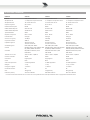
INDEX
TECHNICAL SPECIFICATIONS .................4
DIMENSIONS AND FLYING POINTS .............6
ACCESSORIES .............................8
CONTROL PANEL (FIG.1) .....................9
CONNECTIONS (FIG.2) .....................10
CONFIGURATIONS (FIG.3) ..................11
SAFETY AND PRECAUTIONS .................12
IN CASE OF FAULT .........................12
TROUBLESHOOTING .......................12
CE CONFORMITY ..........................13
PACKAGING, SHIPPING AND COMPLAINT ......13
WARRANTY AND PRODUCTS RETURN .........13
INSTALLATION AND DISCLAIMER .............13
POWER SUPPLY AND MAINTENANCE .........13
GENERAL INFORMATION ...................14
INSTRUCTIONS (FIG. 1 / 2 / 3) ...............14
INDICE
SPECIFICHE TECNICHE ......................5
DIMENSIONI E PUNTI DI SOSPENSIONE. . . . . . . . . 6
ACCESSORI ...............................8
PANNELLO DI CONTROLLO (FIG.1) .............9
CONNESSIONI (FIG.2) ......................10
CONFIGURAZIONI (FIG.3) ...................11
AVVERTENZE PER LA SICUREZZA .............16
IN CASO DI GUASTO .......................16
PROBLEMATICHE COMUNI ..................16
CONFORMITÀ CE ..........................17
IMBALLAGGIO, TRASPORTO E RECLAMI .......17
GARANZIE E RESI .........................17
INSTALLAZIONE E LIMITAZIONI D’USO .........17
ALIMENTAZIONE E MANUTENZIONE ..........17
INFORMAZIONI GENERALI ..................18
ISTRUZIONI (FIG. 1 / 2 / 3) ..................18

4
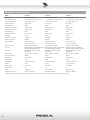
MODEL V10PLUS V12PLUS V15PLUS
System type 2-way vented enclosure 2-way vented enclosure 2-way vented enclosure
High Frequency Device 1’’ neodymium compression driver 1’’ neodymium compression driver 1’’ neodymium compression driver
Low Frequency Device 10” woofer with 2"VC 12” woofer with 2.5"VC 15” woofer with 2.5"VC
Angular Coverage 90° H x 60° V 90° H x 60° V 90° H x 60° V
Total peak power 600 W 600 W 600 W
HF Amplier Cont. Power 50 W Class AB 50 W Class AB 50 W Class AB
LF Amplier Cont. Power 250 W Class D 250 W Class D 250 W Class D
Power Supply type SMPS SMPS SMPS
Frequency Response 60 Hz - 20 kHz 50 Hz - 20 kHz 45 Hz - 20 kHz
Processing Analog Analog Analog
Max SPL at 1mt (peak) 123 dBspl 124 dBspl 126 dBspl
Crossover Frequency 2000 Hz 2000 Hz 2000 Hz
Input Impedance 30 kohm balanced
15 kohm unbalanced
30 kohm balanced
15 kohm unbalanced
30 kohm balanced
15 kohm unbalanced
Input Sensivity LINE: +4 dBu / MIC: -20 dBu LINE: +4 dBu / MIC: -20 dBu LINE: +4 dBu / MIC: -20 dBu
Controls MIC/LINE selector, LEVEL, LOW EQ, HIGH
EQ, GND li, FRONT LED selector.
MIC/LINE selector, LEVEL, LOW EQ, HIGH
EQ, GND li, FRONT LED selector.
MIC/LINE selector, LEVEL, LOW EQ,
HIGH EQ, GND li, FRONT LED selector.
Connectors MIC/LINE: Combo XLR-F / JACK
LINK: XLR-M
MIC/LINE: Combo XLR-F / JACK
LINK: XLR-M
MIC/LINE: Combo XLR-F / JACK
LINK: XLR-M
Power Supply 230 V~ or 120 V~ - 50/60 Hz 230 V~ or 120 V~ - 50/60 Hz 230 V~ or 120 V~ - 50/60 Hz
Rated Consumpon* 300 W 300 W 300 W
Construcon Polypropylene Polypropylene Polypropylene
Cabinet Colour Black Black Black
Flying System 4 x M10 top/boom 4 x M10 top/boom 4 x M10 top/boom
Handles 1 x top 1 x top 1 x top, 2 x sides
Mounng Pole 1 x boom 1 x boom 1 x boom
Monitor taper 45° 44° 44°
Weight 10 Kg (22 lb) 13 Kg (28.6 lb) 18 Kg (39.7 lb)
Dimensions (W x H x D) 330 x 512 x 280 mm 380 x 600 x 328 mm 440 x 712 x 400 mm
* Rated consumpon is measured with pink noise with a crest factor of 12 dB, this can be considered a standard music program.
TECHNICAL SPECIFICATIONS

5
MODELLO V10PLUS V12PLUS V15PLUS
Sistema 2-way vented enclosure 2-way vented enclosure 2-way vented enclosure
Altoparlante al 1’’ neodymium compression driver 1’’ neodymium compression driver 1’’ neodymium compression driver
Altoparlante bassi 10” woofer with 2"VC 12” woofer with 2.5"VC 15” woofer with 2.5"VC
Copertura angolare 90° H x 60° V 90° H x 60° V 90° H x 60° V
Potenza massima di picco 600 W 600 W 600 W
Potenza Connua Amp. Al 50 W Class AB 50 W Class AB 50 W Class AB
Potenza Connua Amp. Bassi 250 W Class D 250 W Class D 250 W Class D
Tipo alimentazione SMPS SMPS SMPS
Risposta in Frequenza 60 Hz - 20 kHz 50 Hz - 20 kHz 45 Hz - 20 kHz
Processamento Analogue Analogue Analogue
SPL max a 1m (picco) 123 dBspl 124 dBspl 126 dBspl
Frequenza Crossover 2000 Hz 2000 Hz 2000 Hz
Impedenza ingresso 30 kohm balanced
15 kohm unbalanced
30 kohm balanced
15 kohm unbalanced
30 kohm balanced
15 kohm unbalanced
Sensibilità ingresso LINE: +4 dBu / MIC: -20 dBu LINE: +4 dBu / MIC: -20 dBu LINE: +4 dBu / MIC: -20 dBu
Controlli MIC/LINE selector, LEVEL, LOW EQ, HIGH
EQ, GND li, FRONT LED selector.
MIC/LINE selector, LEVEL, LOW EQ, HIGH
EQ, GND li, FRONT LED selector.
MIC/LINE selector, LEVEL, LOW EQ,
HIGH EQ, GND li, FRONT LED selector.
Conneori MIC/LINE: Combo XLR-F / JACK
LINK: XLR-M
MIC/LINE: Combo XLR-F / JACK
LINK: XLR-M
MIC/LINE: Combo XLR-F / JACK
LINK: XLR-M
Tensione alim. di rete 230 V~ or 120 V~ - 50/60 Hz 230 V~ or 120 V~ - 50/60 Hz 230 V~ or 120 V~ - 50/60 Hz
Consumo nominale* 300 W 300 W 300 W
Costruzione Polypropylene Polypropylene Polypropylene
Colore Black Black Black
Sistema di sospensione 4 x M10 top/boom 4 x M10 top/boom 4 x M10 top/boom
Maniglie 1 x top 1 x top 1 x top, 2 x sides
Flangia per supporto 1 x boom 1 x boom 1 x boom
Inclinazione monitor 45° 44° 44°
Peso 10 Kg (22 lb) 13 Kg (28.6 lb) 18 Kg (39.7 lb)
Dimensioni (LxAxP) 330 x 512 x 280 mm 380 x 600 x 328 mm 440 x 712 x 400 mm
* Il consumo nominale è misurato con un rumore rosa con un faore di cresta di 12 dB, considerato come un programma standard di musica.
SPECIFICHE TECNICHE

6
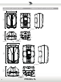
45°
Pole Adapter
M10 Flying Point
33 cm
13"
51.2 cm
20"
28 cm
11"
DIMENSIONS AND FLYING POINTS
DIMENSIONI E PUNTI DI SOSPENSIONE
V12PLUS
V10PLUS
44°
60 cm
23.6"
32.8 cm
12.9"
38 cm
15"
Pole Adapter
M10 Flying Point

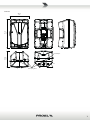
7
V15PLUS
71 cm
28"
40 cm
15.7"
44 cm
17.3"
M10 Flying Point
Pole Adapter
44°

8
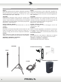
ACCESSORIES
KP210
Adjustable speaker pole for speaker-subwoofer separaon
with terminal pieces Ø 35 mm. Supplied with a bolt
locking mechanism incorporang a steel pin for extra
safety. Adjustment: 825 - 1320 mm.
FRE300BK
Professional aluminium floor-stand for speaker with
terminal pieces Ø 35mm. Supplied with a screw locking
system, a steel safety pin and “Aircushioned” air-damped
release device to grant a exible, fast and easy adjustment.
Adjustment: 1470-2180 mm.
KPTV10 / KPTV12 / KPTV15
C-shape metal bracket for wall mount with +/- 45° free
rotaon.
KPTNX04
Horizontal and Vercal adjustable metal bracket for wall
mount, bar length 25 cm, 12.5° 4 step vert. aiming, 10° 7
step hor. aiming, must be used in conjuncon with KPTV.
PLH300
Single aluminium coupler for 50mm truss with M12 bolt,
always use two couplers with the KPTV for each speaker.
COVERV10 / COVERV12 / COVERV15
Heavy duty cover for carrying.
ACCESSORI
KP210
Supporto distanziatore cassa-subwoofer regolabile in
acciaio con terminali Ø 35mm. Dotato di meccanismo di
chiusura a vite con pin di sicurezza in acciaio. Regolazione:
825 - 1320 mm.
FRE300BK
Supporto professionale in alluminio da pavimento con
terminali Ø 35mm. Con sistema di blocco a vite, pin di
sicurezza in acciaio e disposivo di smorzamento ad aria
per la massima velocità e facilità di regolazione.
Regolazione: 1470-2180 mm.
KPTV10 / KPTV12 / KPTV15
Supporto in metallo a C per montaggio a muro con
rotazione di +/- 45°.
KPTNX04
Sta a in metallo regolabile in orizzontale e vercale per
montaggio a muro, lunghezza barra 25 cm, 4 passi a 12.5°
in vercale e 7 passi a 10° in orizzontale, deve essere usata
con l'accessorio KPTV.
PLH300
Accoppiatore per truss 50mm in alluminio con bullone
M12, usarne sempre due insieme all'accessorio KPTV.
COVERV10 / COVERV12 / COVERV15
Copertura di protezione per il trasporto.
COVERV10 COVERV12 COVERV15
FRE300BK
PLH300
KPTNX04
KP210
KPTV10 KPTV12 KPTV15

9
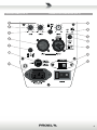
CONTROL PANEL (FIG.1) PANNELLO DI CONTROLLO (FIG.1)

10
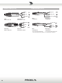
CONNECTIONS (FIG.2) CONNESSIONI (FIG.2)
INPUT (ingresso)
Jack (bilanciato)
INPUT
Jack (balanced)
sleeve - ground
tip - hot
ring - cold
INPUT (ingresso)
XLR bilanciato maschio
INPUT
Balanced male XLR
POWER OUTPUT - uscite altoparlanti
Connettore per cavo tipo Speakon Neutrik NL4
PROEL code - NL4FX
Codice PROEL - NL4FX
PROEL code - NL4FX
Codice PROEL - NL4FX
SPEAKER POWER OUTPUTS
Neutrik NL4 Speakon Cable Connector
ground
hot
cold
INPUT (ingresso)
Jack (sbilanciato)
INPUT
Jack (unbalanced)
ground
tip - hot
cold
*nota: connettere insieme cold e ground
per cavi da bilanciato a sbilanciato
*note: connect both cold and ground
to make cable from balanced to unbalanced
2-
1+
2+
1-
20mm
0.8"
8mm
0.3"
RED
BLACK
positive / red / rosso
n.c.
1+
negative / black / nero
1-
n.c.
POWER OUTPUT - uscite altoparlanti
Connettore per cavo tipo Speakon Neutrik NL4
SPEAKER POWER OUTPUTS
Neutrik NL4 Speakon Cable Connector
2-
1+
2+
1-
channel 1 positive
canale 1 positivo
1+
channel 1 negative
canale 1 negativo
1-
OUTPUT 1
2-
1+
2+
1-
bridge positive
n.c.
1+
bridge negative
1-
n.c.
OUTPUT BRIDGE
2-
1+
2+
1-
20mm
0.8"
8mm
0.3"
RED
BLACK
channel 2 positive
n.c.
1+
channel 2 negative
1-
n.c.
OUTPUT 2
uscita 1 uscita BRIDGE uscita 2
channel 2 negative
canale 2 negativo
NOTE: channels 3 and 4 are equal to channel 1 and 2 respectively.
NOTA: canali 3 e 4 sono equivalenti ai canali 1 e 2 rispettivamente.
2+
channel 2 positive
canale 2 positivo
2-
LINK (uscita)
XLR bilanciato femmina
LINK (output)
Bala
nced female XLR
ground
hot
cold

11
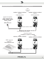
CONFIGURATIONS (FIG.3) CONFIGURAZIONI (FIG.3)
R
L
PROEL suggested
equipment:
Mi and M series mixer
dynamic microphone
PROEL suggested types:
DM580 - DM586 - DM226
DM220 - DM800
or
WM wireless mic
RIGHT
V10PLUS / V12PLUS / V15PLUS
LEFT
V10PLUS / V12PLUS / V15PLUS
stereo basic system
2x V10PLUS / V12PLUS / V15PLUS
V10PLUS / V12PLUS / V15PLUS
(mic in)
single voice system
V10PLUS / V12PLUS / V15PLUS
(mic in)
double voice system
basic
conference
system
set this switch as “LINE”
use preferably balanced cables
set this switch as “MIC”

12
SAFETY AND PRECAUTIONS
• CAUTION: before using this product read carefully the following safety instrucons. Take a look of this manual enrely and preserve it for
future reference.
When using any electric product, basic precauons should always be taken, including the following:
– To reduce the risk, close supervision is necessary when the product is used near children.
– Protect the apparatus from atmospheric agents and keep it away from water, rain and high humidity places.
– This product should be site away from heat sources such as radiators, lamps and any other device that generate heat.
– This product should be located so that its locaon or posion does not interfere with its proper venlaon and heang dissipaon.
– Care should be taken so that objects and liquids do not go inside the product.
– The product should be connected to a power supply mains line only of the type described on the operang instrucons or as marked on the
product. Connect the apparatus to a power supply using only power cord included making always sure it is in good condions.
–
WARNING: The mains plug is used as disconnect device, the disconnect device shall remain readily operable.
– Do not cancel the safety feature assured by means of a polarized line plug (one blade wider than the other) or with a earth connecon.
– Make sure that power supply mains line has a proper earth connecon.
– Power supply cord should be unplugged from the outlet during strong thunderstorm or when le unused for a long period of me.
– Do not place objects on the product’s power cord or place it in a posion where anyone could trip over, walk on or roll anything over it. Do not
allow the product to rest on or to be installed over power cords of any type. Improper installaons of this type create the possibility of re hazard
and/or personal injury.
– This product may be capable of producing sound levels that could cause
permanent hearing loss. Exposure to extremely high noise levels may cause
permanent hearing loss. Individuals vary considerably in suscepbility to noise-
induced hearing loss, but nearly everyone will lose some hearing if exposed
to sufficiently intense noise for a period of time. The U.S. Government’s
Occupational Safety and Health Administration (OSHA) has specified the
permissible noise level exposures shown in the following chart. According to
OSHA, any exposure in excess of these permissible limits could result in some
hearing loss. To ensure against potenally dangerous exposure to high sound
pressure levels, it is recommended that all persons exposed to equipment
capable of producing high sound pressure levels use hearing protectors while
the equipment is in operaon. Ear plugs or protectors in the ear canals or over
the ears must be worn when operang the equipment in order to prevent
permanent hearing loss if exposure is in excess of the limits set forth here. Keep
your's aenon that children and pets are more suscepble to excessive noise
levels.
IN CASE OF FAULT
• In case of fault or maintenance this product should be inspected only by qualied service personnel when:
– There is a aw either in the connecons or in the supplied connecng cables.
– Liquids have spilled inside the product.
– The product has fallen and been damaged.
– The product does not appear to operate normally or exhibits a marked change in performance.
– The product has been lost liquids or gases or the enclosure is damaged.
• Do not operate on the product, it has no user-serviceable parts inside, refer servicing to an authorized maintenance centre.
TROUBLESHOOTING
No Power • The loudspeaker's "POWER" switch is o.
• Make sure the mains AC outlet is live (check with a tester or a lamp).
• Make sure the mains plug is securely plugged into mains AC outlet.
No Sound • Is the input LEVEL control for the channel turned up?
• Is the SIGNAL LED illuminated? If not check if your signal level is too low or check the signal cable, mixer and other
equipment seng and cabling.
• Are you sure your signal cables works properly? check it using a cable tester or replacing with a new one.
• Are you sure your power cable works properly? check it using a cable tester or replacing with a new one.
Distorted Sound • Input signal level is too high. Turn down your level controls.
NOTE: The loudspeakers should never be operated at a level which causes the amplier Clip LEDs to illuminate
constantly.
Dierent channel
level
• Check if are using a balanced cable for one channel and an unbalanced one for the other, as this would cause a
considerable dierence in channel levels.
Noise / Hum • Enable GND LIFT buon on rear panel, if the problem persist press all GND LIFT buons for all system's ampliers.
• Whenever possible, preferably use only balanced cables. Unbalanced lines may also be used but may result in noise
over long cable runs.
• Somemes it helps to plug all audio equipment into the same AC circuit so they share a common ground.
Duraon Per Day
In Hours
Sound Level dBA
Slow Response
Typical
Example
8 90 Duo in small club
6 92
4 95 Subway Train
3 97
2 100 Very loud classical music
1.5 102
1 105 Trac noise
0.5 110
0.25 or less 115 Loudest parts at a rock concert

13
CE CONFORMITY
• Proel products comply with direcve EMC 2014/30/CE, as stated in EN 55103-1 and EN 55103-2 standards and with direcve LVD 2014/35/CE,
as stated in EN 60065 standard.
• Under the EM disturbance, the rao of signal-noise will be changed above 10dB.
PACKAGING, SHIPPING AND COMPLAINT
• This unit package has been submied to ISTA 1A integrity tests. We suggest you control the unit condions immediately aer unpacking it.
• If any damage is found, immediately advise the dealer. Keep all unit packaging parts to allow inspecon.
• Proel is not responsible for any damage that occurs during shipment.
• Products are sold “delivered ex warehouse” and shipment is at charge and risk of the buyer.
• Possible damages to unit should be immediately noed to forwarder. Each complaint for package tampered with should be done within eight
days from product receipt.
WARRANTY AND PRODUCTS RETURN
• Proel products have operang warranty and comply their specicaons, as stated by manufacturer.
• Proel warrants all materials, workmanship and proper operaon of this product for a period of two years from the original date of purchase. If
any defects are found in the materials or workmanship or if the product fails to funcon properly during the applicable warranty period, the owner
should inform about these defects the dealer or the distributor, providing receipt or invoice of date of purchase and defect detailed descripon.
This warranty does not extend to damage resulng from improper installaon, misuse, neglect or abuse. Proel S.p.A. will verify damage on returned
units, and when the unit has been properly used and warranty is sll valid, then the unit will be replaced or repaired. Proel S.p.A. is not responsible
for any "direct damage" or "indirect damage" caused by product defecveness.
INSTALLATION AND DISCLAIMER
• Proel products have been expressly designed for audio applicaon, with signals in audio range (20Hz to 20kHz). Proel has no liability for damages
caused in case of lack of maintenance, modicaons, improper use or improper installaon non-applying safety instrucons.
• The installaon of these speakers is provided for indoors, in case of use outdoors be sure that the speakers are installed correctly in a safe
locaon protected from wind, rain and humidity. To avoid performance deterioraon of mechanical, acouscs and electrical parts is not advisable
to leave these speakers exposed outdoors for a long period of me, so we suggest a temporary installaon for the limited sound events.
• The installaon of these speakers is provided for oor or by means of specic stands able to support their weight. Therefore avoid installaon
on unstable elements such as: furniture, chairs and vibrant surfaces as stages or other speakers without appropriate x point specically designed
to avoid speaker movement. Then avoid the use of inadequate supports, we suggest to use PROEL stands and accessories only.
• In case of the speakers are provided of rigging points: DO NOT SUSPEND THE SPEAKERS FROM THE HANDLES, use exclusively these rigging points.
Consult professional rigger or structural engineers prior to suspending loudspeakers from a structure not intended for that use. Always know the
working load limit of the structure supporng the loudspeakers. Always make sure that the rigging hardware minimum rang is at least ve mes
the actual load, speakers and rigging hardware.
• In case of suspended installaons of acve loudspeakers where is not possible to turn on and o the speakers from their appropriate switches,
we recommend to install switches on the mains lines, for this purpose consult an expert electrician for the exact dimension of wiring.
• Locate the speakers as far away as possible from radio or television receivers or other sensive equipment. These speakers have a strong
magnec eld which can induce hum and noise into unshielded devices that are located nearby with consequent deterioraon of recepon of
image and sound.
• Proel S.p.A. reserves the right to change these specicaons at any me without noce.
• Proel S.p.A. declines any liability for damages to objects or persons caused by lacks of maintenance, improper use, installaon not performed
with safety precauons and at the state of the art.
POWER SUPPLY AND MAINTENANCE
• Clean only with dry cloth.
• Check periodically that the slots for its proper venlaon and heang dissipaon are not obstructed by dust, remove the dust using a dry brush
or a compressed air gun.
• The amplied loudspeakers of Proel have been designed with CLASS I construcon and must be connected always to a mains socket outlet with
a protecve earth connecon (the third grounding prong).
• Before connecng the product to the mains outlet make certain that the mains line voltage matches that shown on the rear of the product, a
tolerance of up to ±10% is acceptable.
• Inside the amplied loudspeakers are present special safety devices such as:
ü Protecon against excessive power applied at each speaker.
•
THE REPLACEMENT OF FUSES INSIDE THE APPARATUS MUST BE MADE ONLY BY QUALIFIED PERSONNEL.
•
CHECK THE CONDITION OF THE PROTECTION FUSE, ACCESSIBLE OUTWARD, ONLY WITH THE APPARATUS SWITCHED OFF AND DISCONNECTED
FROM THE MAINS LINE OUTLET.
•
REPLACE THE PROTECTION FUSE ONLY WITH SAME TYPE AS SHOWN ON THE PRODUCT.
•
IF AFTER THE SUBSTITUTION, THE FUSE INTERRUPTS AGAIN THE APPARATUS WORKING, DO NOT TRY AGAIN THEN CONTACT THE PROEL
SERVICE CENTRE.

14
GENERAL INFORMATION
Thank you for having chosen a PROEL product.
V PLUS series is the evoluon of the acclaimed V series of PROEL powered loudspeakers delivering absolute value in
terms of performance, engineering and design at a more aordable cost. These ultra-portable speakers combine, in
carefully engineered and light-weight cabinets, the clearest and most accurate PROEL sound with Class D amplier
technology and Switch Mode Power Supply, oering an unbeatable PA soluon at its price point.
The three models, V10PLUS, V12PLUS and V15PLUS, feature an extremely ecient amplier module capable of
delivering 600 W of robust power to the transducers. Thanks to the use of SMPS technology, this power comes in an
ultra-lightweight package, making the V PLUS the most portable PROEL speakers ever. The power module is hosted in a
fully sealed aluminium box, which provides protecon, perfect insulaon of the cabinet from the outside and extremely
ecient cooling.
Thanks to the carefully selected speakers and to the sophiscated acve electronics, including dual CLIP LIMITERS for
an undistorted sound even at the loudest level, the sound of the V PLUS has been precisely tuned in every details, in
order to provide unheard performance in this price range.
The V PLUS cabinets, expression of the most advanced Italian design, include a super-comfortable luggage-style top
handle for an eortless portability. The slanted shape allows the speakers to be laid on their side and used also as stage
monitors.
INSTRUCTIONS (FIG. 1 / 2 / 3)
1. INPUT (combo XLR-JACK input)
This is a female combo connector, which accepts a XLR or a JACK plug from almost any type of equipment with a
balanced or unbalanced outputs. The XLR input is wired as follows:
Pin 1 = shield or ground
Pin 2 = + posive or "hot"
Pin 3 = - negave or "cold"
The JACK input is wired as follows:
Tip = + posive or "hot"
Ring = - negave or "cold"
Sleeve = shield or ground
When connecng an unbalanced signal, wire them as follows:
Pin2 / Tip = + posive or "hot"
Pin 1-3 / Sleeve = shield or ground
NOTE: whenever possible, use always balanced cables. Unbalanced lines may also be used but may result in noise over
long cable runs. In any case, avoid using a balanced cable for one channel and an unbalanced one for the other.
2. LINK (XLR output)
This is a male XLR connector, it is connected in parallel with the respecve INPUT socket, so the LINK is wired as INPUT.
Connect these to the inputs of other powered speakers to make an array.
3. MIC / LINE switch
This switch adjusts the gain of the LINE/MIC input varying the sensivity between MIC, suited to connect a microphone,
and LINE, suited to connect a device with high level output like a MIXER, a CD player etc.
NOTE: do not use the MIC sensivity to "pump up" the volume with the LINE level equipment, in order to avoid the
analogue input saturaon that could produce very annoying distoron.
4. GND LIFT switch
This switch li the ground of the balanced audio inputs from the earth-ground of the amplier. If you have HUM noise
problem on one or more loudspeaker try to change the posion of these switches (oen all up or all down for all the
ampliers in the system). Please note that to have an eect all cables must be balanced.
5. LEVEL control
Rotary level control: it aenuates the level of the signal sent to the INPUT. The aenuaon ranges from “0” fully closed
(the signal is completely aenuated) to “10” fully open, nominal level (the signal is not aenuated in any way, so it is
fed to the internal amplier at the same level at which it arrives on input).
6. LOW control
This control gives you up to 6 dB boost or cut at 90 Hz with a "SHELVING" curve shape. Use it to add or reduce the sound
"punch", or to reduce the low frequency rise when the speaker is set near walls or on oor as stage monitor.

15
7. HIGH control
This control gives you up to 6 dB boost or cut at 8 KHz with a "SHELVING" curve shape. Use it to add or reduce the sound
"clarity" and "brightness".
8. SIGN/LIMIT indicator
GREEN LED illuminates to indicate the presence of the signal at the amplier input.
RED LED illuminates when the internal amplier's output is limited. When this LED ashes reduce the input signal
level.
9. ON indicator
GREEN LED: when lighted indicates amplier has been turned on and AC power is available.
10. FRONT LED switch
This switch enables the front LED to indicate the speaker power ON status or to replicate the SIGNAL/LIMIT
indicaon.
11. POWER switch
Speaker is "ON" when the switch is in the "I" posion, use this switch to set the speaker power to ON or OFF.
NOTE: When you shut down your equipment, turn o the speaker rst. When powering up, turn on the speaker last.
12. LINE VOLTAGE selector
This switch sets the AC voltage line of your country (usually it is set by factory and isn't necessary to change it). The
115V seng is for mains line in the range of 105-120V~ and 230V seng is for mains line in the range of 210-240V~.
WARNING: AN INCORRECT SETTING OF AC LINE VOLTAGE COULD DAMAGE SERIOUSLY THE INTERNAL
ELECTRONICS!
13. FUSE holder
Here is placed the mains protecon fuse.
WARNING: REPLACE THE PROTECTION FUSE ONLY WITH SAME TYPE AS SHOWN ON THE PRODUCT.
IF AFTER THE SUBSTITUTION, THE FUSE INTERRUPTS AGAIN THE APPARATUS WORKING, DO NOT TRY AGAIN
THEN CONTACT THE PROEL SERVICE CENTER.
14. AC~ socket
Here’s where you plug in your speaker’s mains supply cord. You should always use the mains cord supplied with the
speaker. Be sure your speaker is turned o before you plug the mains supply cord into an electrical outlet.

16
AVVERTENZE PER LA SICUREZZA
• ATTENZIONE: Durante le fasi di uso o manutenzione, devono essere prese alcune precauzioni onde evitare danneggiamen alle struure
meccaniche ed eleroniche del prodoo.
Prima di ulizzare il prodoo, si prega di leggere aentamente le seguen istruzioni per la sicurezza. Prendere visione del manuale d’uso e
conservarlo per successive consultazioni:
– In presenza di bambini, controllare che il prodoo non rappresen un pericolo.
– Posizionare l’apparecchio al riparo dagli agen atmosferici e a distanza di sicurezza dall’acqua, dalla pioggia e dai luoghi ad alto grado di
umidità.
– Collocare o posizionare il prodoo lontano da fon di calore quali radiatori, griglie di riscaldamento e ogni altro disposivo che produca
calore.
– Collocare o posizionare il prodoo in modo che non ci siano ostruzioni alla sua propria venlazione e dissipazione di calore.
– Evitare che qualsiasi oggeo o sostanza liquida entri all’interno del prodoo.
– Il prodoo deve essere connesso esclusivamente alla rete elerica delle caraerische descrie nel manuale d’uso o scrie sul prodoo,
usando esclusivamente il cavo rete in dotazione e controllando sempre che sia in buono stato, in parcolare la spina e il punto in cui il cavo esce
dal prodoo.
–
ATTENZIONE: Se il cavo rete viene scollegato dall'apparecchio per spegnerlo, il cavo rete rimarrà operavo in quanto la sua spina è ancora
collegata alla rete elerica.
– Non annullare la sicurezza garanta dall'uso di spine polarizzate o con messa a terra.
– Fare aenzione che il punto di alimentazione della rete elerica sia dotato di una eciente presa di terra.
– Disconneere il prodoo dalla rete elerica durante for temporali o se non viene usato per un lungo periodo di tempo.
– Non disporre ogge sul cavo di alimentazione, non disporre i cavi di alimentazione e segnale in modo che qualcuno possa inciamparci. Altresì
non disporre l’apparecchio sui cavi di altri appara. Installazioni inappropriate
di questo po possono creare la possibilità di rischio di incendio e/o danni alle
persone.
– Questo prodoo può essere capace di produrre livelli sonori che possono
causare perdite d’udito permanen. Si raccomanda di evitare l’esposizione
ad alti livelli sonori o livelli non confortevoli per lunghi periodi di tempo.
Se si notano perdite d’udito o acufeni (schi) consultare un audiologo. La
sensibilità alla perdita di udito causata da eccessiva esposizione al rumore varia
considerevolmente da individuo a individuo, ma mediamente ciascuno può
accusare perdita di udito se esposto al rumore per un certo periodo di tempo.
Come suggerimento viene riportata la tabella dei tempi massimi di esposizione
giornaliera al rumore al ne di evitare perdite di udito, fonte della tabella è l'ente
per la salute degli Sta Uni (OSHA).
Si fa presente inoltre che sia i bambini che gli animali domesci sono più sensibili
al rumore intenso.
IN CASO DI GUASTO
• In caso di guasto o manutenzione questo prodoo deve essere ispezionato da personale qualicato quando:
– Ci sono dife sulle connessioni o sui cavi di collegamento in dotazione.
– Sostanze liquide sono penetrate all’interno del prodoo.
– Il prodoo è caduto e si è danneggiato.
– Il prodoo non funziona normalmente esibendo una marcato cambio di prestazioni.
– Il prodoo perde sostanze liquide o gassose o ha l’involucro danneggiato.
• Non intervenire sul prodoo. Rivolgersi a un centro di assistenza autorizzato Proel.
PROBLEMATICHE COMUNI
Assenza di
alimentazione
• L'interruore dell'altoparlante è spento.
• Accertarsi che ci sia eevamente tensione sulla presa di corrente (controllare con un tester o una lampada).
• Accertarsi che la spina di rete sia saldamente inserita nella presa.
Nessun Suono • È il controllo di livello LINE IN girato al massimo?
• È acceso il LED di segnale? Se no, controllate se il livello di segnale sia troppo basso o controllate il cavo di segnale,
le impostazioni e i cablaggi di mixer o altri apparecchi collega.
• Sei sicuro che il cavo di segnale sia in buono stato? controlla il cavo con un tester oppure sostuiscilo con un altro.
Suono Distorto • Il livello del segnale di ingresso è troppo alto, abbassare i controlli del livello.
NOTA: L'altoparlante non deve mai lavorare con livelli che fanno illuminare in modo pressoché costante il LED rosso
dell'amplicatore.
Livello dierente sui
canali
• Controllare se si stanno usando cavi bilancia su un canale e sbilancia sull'altro, ciò può comportare una notevole
dierenza di livello sui canali.
Rumore / Ronzio • Abilitare l'interruore GND LIFT sul pannello posteriore, se il problema persiste premere i GND LIFT su tu gli
amplicatori del sistema.
• Qualora possibile, usare preferibilmente solo cavi bilancia. Cavi sbilancia possono essere usa ma risultano
rumorosi su lunghe distanze.
• Talvolta può essere di aiuto alimentare tuo l'equipaggiamento audio collegandolo dalla stessa linea di corrente
AC, in modo che tu gli appara condividano la stessa presa di terra.
Ore di esposizione
giornaliera
Livello sonoro in dBA
costante di tempo SLOW
Esempio
Tipico
8 90 Duo acusco in un piccolo club
6 92
4 95 Treno metropolitano
3 97
2 100 Musica classica molto forte
1.5 102
1 105 Rumore da traco urbano intenso
0.5 110
0.25 or less 115 Parte più rumorosa di un concerto rock

17
CONFORMITÀ CE
• I Prodo Proel sono conformi alla direva EMC 2014/30/CE, secondo gli standard EN 55103-1 ed EN 55103-2 ed alla direva LVD 2014/35/
CE, secondo lo standard EN 60065.
• Se sooposto a disturbi EM, il rapporto segnale-rumore può essere superiore a 10dB.
IMBALLAGGIO, TRASPORTO E RECLAMI
• L’imballo è stato sooposto a test di integrità secondo la procedura ISTA 1A. Si raccomanda di controllare il prodoo subito dopo l’apertura
dell’imballo.
• Se vengono riscontra danni informare immediatamente il rivenditore. Conservare quindi l’imballo completo per permeerne l’ispezione.
• Proel declina ogni responsabilità per danni causa dal trasporto.
• Le merci sono vendute “franco nostra sede” e viaggiano sempre a rischio e pericolo del distributore.
• Eventuali avarie e danni dovranno essere contesta al veore. Ogni reclamo per imballi manomessi dovrà essere inoltrato entro 8 giorni dal
ricevimento.
GARANZIE E RESI
• I Prodo Proel sono provvis della garanzia di funzionamento e di conformità alle proprie speciche, come dichiarate dal costruore.
• La garanzia di funzionamento è di 24 mesi dopo la data di acquisto. I dife rileva entro il periodo di garanzia sui prodo vendu, aribuibili a
materiali difeosi o dife di costruzione, devono essere tempesvamente segnala al proprio rivenditore o distributore, allegando evidenza scria
della data di acquisto e descrizione del po di difeo riscontrato. Sono esclusi dalla garanzia dife causa da uso improprio o manomissione. Proel
SpA constata tramite verica sui resi la difeosità dichiarata, correlata all’appropriato ulizzo, e l’eeva validità della garanzia; provvede quindi
alla sostuzione o riparazione dei prodo, declinando tuavia ogni obbligo di risarcimento per danni dire o indire eventualmente derivan
dalla difeosità.
INSTALLAZIONE E LIMITAZIONI D’USO
• I Prodo Proel sono desna esclusivamente ad un ulizzo specico di po sonoro: segnali di ingresso di po audio (20Hz-20kHz). Proel declina
ogni responsabilità per danni a terzi causa da mancata manutenzione, manomissioni, uso improprio o installazione non eseguita secondo le
norme di sicurezza.
• L'installazione di ques altoparlan è prevista per uso interno, in caso di ulizzo all'esterno assicurarsi che gli altoparlan siano installa
correamente in un luogo sicuro e proteo dal vento, pioggia e umidità. Al ne di non deteriorarne le prestazioni meccaniche, acusche ed
eleriche non è consigliato lasciare ques altoparlan espos all'aperto per lunghi periodi di tempo, si consiglia pertanto una installazione
temporanea all'evento da sonorizzare.
• L'installazione di ques altoparlan è prevista a pavimento o tramite specici suppor adegua al peso da sostenere. Pertanto evitare
l'installazione su elemen instabili quali: mobili, sedie e superci vibran quali palchi e altri altoparlan non dota di ssaggi a a evitare
spostamen dell'altoparlante. Quindi evitare di ulizzare suppor non adegua, si consiglia di usare solo i suppor suggeri da PROEL.
• Qualora gli altoparlan siano muni di pun di ssaggio per la sospensione: NON SOSPENDERE GLI ALTOPARLANTI DALLE MANIGLIE usare
esclusivamente ques pun di ssaggio. Consultare arezzis professionis o ingegneri struurali prima di sospendere altoparlan da struure non
intese per questo specico scopo. Non superare il limite di carico della struura che sosterrà gli altoparlan. Assicurarsi che tue le meccaniche
di sostegno siano in grado di sopportare un peso almeno 5 volte superiore al carico degli altoparlan incluse le meccaniche di sospensione.
• Nel caso di installazioni sospese di altoparlan avi in cui non sia possibile l'uso dei singoli interruori degli altoparlan per l'accensione e lo
spegnimento dei medesimi, si raccomanda l'installazione di interruori sulle linee di alimentazione della rete elerica, a tale proposito consultare
un esperto elericista per il correo dimensionamento dell'impianto elerico.
• Installare ques altoparlan il più lontano possibile da radioricevitori e televisori. Un altoparlante installato in prossimità di ques appara può
causare interferenza e rumore con conseguente degrado della ricezione di immagini e suoni.
• La Proel S.p.a. si riserva di modicare il prodoo e le sue speciche senza preavviso.
• Proel declina ogni responsabilità per danni a terzi causa da mancata manutenzione, manomissioni, uso improprio o installazione non eseguita
secondo le norme di sicurezza e a regola d'arte.
ALIMENTAZIONE E MANUTENZIONE
• Pulire il prodoo unicamente con un panno asciuo.
• Controllare periodicamente che le aperture di rareddamento non siano ostruite da accumuli di polvere, provvedere alla rimozione della polvere
mediante un pennello o aria compressa.
• Gli altoparlan amplica della Proel sono costrui in CLASSE I e prevedono sempre il collegamento mediante presa di corrente con terminale
di terra di protezione (terzo terminale di terra).
• Prima di collegare l'apparecchio alla presa di corrente, accertatevi che la tensione di rete corrisponda a quella indicata sul retro dell’apparato, è
consento un margine del ±10% rispeo al valore nominale.
• Negli altoparlan amplica sono presen anche i seguen disposivi di sicurezza:
ü protezioni alla potenza erogata in eccesso ai singoli altoparlan.
•
LA SOSTITUZIONE DI FUSIBILI ALL'INTERNO DELL'APPARATO È CONSENTITO SOLAMENTE A PERSONALE QUALIFICATO.
•
CONTROLLARE LO STATO DEI FUSIBILI DI PROTEZIONE ESCLUSIVAMENTE AD APPARATO SPENTO E DISCONNESSO DALLA RETE ELETTRICA.
•
RIMPIAZZARE IL FUSIBILE DI PROTEZIONE ESCLUSIVAMENTE CON UN FUSIBILE CON LE MEDESIME CARATTERISTICHE RIPORTATE SUL
PRODOTTO.
•
SE DOPO LA SOSTITUZIONE, IL FUSIBILE INTERROMPE NUOVAMENTE IL FUNZIONAMENTO DELL'APPARATO, NON INSISTERE E CONTATTARE
IL SERVIZIO ASSISTENZA PROEL.

18
INFORMAZIONI GENERALI
Grazie per aver scelto un prodoo PROEL.
La nuova serie V PLUS è l'evoluzione dell'acclamata serie V di diusori amplica PROEL in grado di orirvi il massimo
valore possibile in termini di prestazioni, innovazione e design ad un prezzo ancora più conveniente. Ques diusori
ultra-portali uniscono, in cabinets leggeri e accuratamente progea, il suono PROEL più deagliato alla tecnologia in
Classe D con Switch Mode Power Supply per gli amplicatori, orendo una soluzione per la diusione acusca imbabile
in questa categoria di prezzo.
I tre modelli V10PLUS, V12PLUS e V15PLUS includono un modulo di amplicazione estremamente eciente, in grado di
fornire ai trasduori 600 W di potenza totale. Grazie all’ulizzo della tecnologia SMPS, questa potenza viene generata
da un disposivo ultra-leggero, facendo dei modelli V PLUS i diusori PROEL più portali di sempre. I moduli di potenza
sono alloggia in box di alluminio totalmente sigilla, che forniscono la massima protezione, un isolamento perfeo
del cabinet dall’esterno e un sistema di rareddamento parcolarmente eciente.
Grazie agli altoparlan seleziona e alla soscata eleronica ava, che include un doppio circuito di LIMITER per un
suono indistorto anche ai massimi livelli, il suono della serie V PLUS è stato accuratamente denito in modo da orire
una performance sorprendente per questa fascia di prezzo.
I cabinets della serie V PLUS, espressione del più avanzato design Italiano, includono una super-comoda maniglia
superiore in sle valigea per un trasporto senza sforzi. Il prolo inclinato ne consente l’ulizzo anche su un anco
come monitor da palco.
ISTRUZIONI (FIG. 1 / 2 / 3)
1. INPUT (ingresso COMBO XLR/JACK)
Questo è un conneore combinato XLR/JACK femmina che preleva il segnale da pracamente qualsiasi apparecchio
bilanciato o sbilanciato. Le terminazioni dell'ingresso XLR sono:
Pin 1 = schermo o massa
Pin 2 = + posivo o "caldo"
Pin 3 = - negavo o "freddo"
Le terminazioni dell'ingresso JACK sono:
Tip (punta) = + posivo o "caldo"
Ring (anello) = - negavo o "freddo"
Sleeve (manicoo) = schermo o massa
E quando si collega un segnale sbilanciato, sono le seguen:
Pin2 / Tip (punta) = + posivo o "caldo"
Pin 1-3 / Sleeve (manicoo) = schermo o massa
NOTA: Se possibile, usare sempre cavi bilancia. Cavi sbilancia possono essere usa ma potrebbero dare problemi di
rumore se molto lunghi. In ogni caso, evitate di usare un cavo bilanciato per un canale e uno sbilanciato per l’altro.
2. LINK (XLR uscita)
Questo è un conneore XLR maschio connesso in parallelo con il rispevo conneore INPUT, perciò il LINK è terminato
come il LINE IN. Collegarlo ad altri altoparlan amplica per realizzare un complesso sistema di rinforzo sonoro.
3. MIC / LINE (seleore sensibilità linea / microfono)
Questo seleore cambia la sensibilità dell'ingresso variando il guadagno tra MIC, adao a collegare direamente un
microfono, e LINE, adao a collegare una apparecchiatura con uscita di livello elevato quale un MIXER, un leore CD,
etc.
NOTE: non usare la sensibilità MIC per "pompare" il volume con apparecchi a livello LINEA, onde evitare la saturazione
del circuito di ingresso che può produrre una distorsione molto sgradevole.
4. GND LIFT (interruore sollevamento massa)
Questo interruore solleva la massa degli ingressi audio bilancia dalla massa-terra dell'amplicatore. Se si hanno
problemi di ronzio su uno o più altoparlan provare a cambiare la posizione di ques interruori: perché abbiano eeo
spesso occorre siano tu su o tu giù per tu gli amplicatori e che tu i cavi siano bilancia.
5. LEVEL (controllo di livello ingresso linea)
Controllo di livello rotavo: aenua il livello del segnale inviato all'amplicatore interno. L'aenuazione varia tra
completamente chiuso “0” a completamente aperto “10” o livello nominale (il segnale non è aenuato in nessun modo,
viene inviato all'amplicatore interno allo stesso livello con cui arriva all'ingresso).

19
6. EQ LOW (equalizzatore controllo bassi)
Questo controllo permee di guadagnare o aenuare no a 6 dB a 90 Hz con una curva di po "SHELVING". Da usarsi
per aumentare o ridurre il "vigore" del suono, o per ridurre l'aumento delle basse frequenze quando l'altoparlante è
posizionato vicino a muri o sul pavimento come monitor da palco.
7. HIGH (equalizzatore controllo al)
Questo controllo permee di guadagnare o aenuare no a 6 dB a 8 KHz con una curva di po "SHELVING". Da usarsi
per aumentare o ridurre la "chiarezza" o "brillanza" del suono.
8. SIGN/LIMIT (indicatore di segnale e clip limiter)
LED VERDE che si accende per indicare la presenza del segnale sull'ingresso dell'amplicatore.
LED ROSSO che si accende quando l'uscita dell'amplicatore interno è limitata. Quando questo LED lampeggia ridurre
il segnale di ingresso.
9. ON (indicatore di accensione)
LED VERDE: quando acceso indica che l'altoparlante è stato acceso e l'alimentazione AC è disponibile.
10. FRONT LED (interruore)
Questo interruore abilita il LED frontale ad indicare lo stato di accensione dell'altoparlante od a replicare l'indicazione
SIGNAL/LIMIT.
11. POWER (interruore di accensione)
L'altoparlante è acceso "ON" quando l'interruore è nella posizione "I". Agite su questo tasto per accendere o spegnere
l'altoparlante.
NOTA: Quando si spegne l'impianto sonoro, spegnere per primi gli altoparlan. Quando si accende l'impianto sonoro,
accendere gli altoparlan per ulmi.
12. LINE VOLTAGE (seleore tensione di rete)
Questo seleore imposta la tensione di rete della linea elerica del vostro paese (picamente è già impostato di fabbrica
e non è necessario cambiarlo). L'impostazione 115V è per le linee eleriche da 105-120V~ e l'impostazione 230V è per
le linee eleriche da 210-240V~.
ATTENZIONE: UNA SBAGLIATA IMPOSTAZIONE DELLA LINEA ELETTRICA AC LINE VOLTAGE PUÒ DANNEGGIARE
SERIAMENTE L'AMPLIFICATORE INTERNO.
13. FUSE (portafusibili)
In questo vano è inserito il fusibile di protezione principale di rete.
ATTENZIONE: RIMPIAZZARE IL FUSIBILE DI PROTEZIONE ESCLUSIVAMENTE CON UN FUSIBILE CON LE MEDESIME
CARATTERISTICHE RIPORTATE SUL PRODOTTO.
SE DOPO LA SOSTITUZIONE, IL FUSIBILE INTERROMPE NUOVAMENTE IL FUNZIONAMENTO DELL'APPARATO, NON
INSISTERE E CONTATTARE IL SERVIZIO ASSISTENZA PROEL.
14. AC~ (presa di alimentazione di rete)
In questa presa va inserito il cavo di alimentazione di rete dell'altoparlante. Si raccomanda di ulizzare esclusivamente
il cavo di alimentazione in dotazione all'altoparlante. Accertarsi che l'altoparlante sia spento prima di inserire il cavo di
alimentazione nella presa di corrente.

REV. 37/17 CODE 96MAN0126
PROEL S.p.A.
(World Headquarter)
Via alla Ruenia 37/43
64027 Sant’Omero (TE) - ITALY
Tel: +39 0861 81241
Fax: +39 0861 887862
www.proel.com
-
 1
1
-
 2
2
-
 3
3
-
 4
4
-
 5
5
-
 6
6
-
 7
7
-
 8
8
-
 9
9
-
 10
10
-
 11
11
-
 12
12
-
 13
13
-
 14
14
-
 15
15
-
 16
16
-
 17
17
-
 18
18
-
 19
19
-
 20
20


PROEL V12Plus Manuale utente
- Tipo
- Manuale utente
in altre lingue
- English: PROEL V12Plus User manual