V2 Elettronica V2 Touch CMM Manuale del proprietario
- Tipo
- Manuale del proprietario
La pagina si sta caricando...

Questo dispositivo viene installato per la prevenzione degli
infortuni su cancelli scorrevoli ed accessi automatizzati.
Il suo funzionamento è assicurato anche nella condizione limite in
c
ui l'estruso in gomma risultasse lacerato ed in caso di guasto,
provoca l'arresto dell'automazione.
In conformità alle vigenti norme sulla sicurezza, le coste
meccaniche sono composte da una costa in gomma a doppia
camera con dopocorsa elastico di ammortamento urto superiore
ai 50mm e da un profilo in alluminio di uguale lunghezza, che
fissato al pilastro farà da supporto all'estruso in gomma.
I
l funzionamento della costa è garantito da due micro-switches: Il
primo lavora su deformazione della gomma, il secondo come
sicurezza nel caso in cui il dispositivo si guastasse.
INSTALLAZIONE
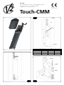
1. Fissare la staffa (part. 1 dis. 1.1) sul montante, ponendo
attenzione alle quote della tabella, colonna
B.
2. Inserire l’estruso nella staffa e fissarlo nei fori predisposti
(part. 2-3 dis. 1.1). In questo modo l’estruso risulta fissato in
tre punti senza doverlo smontare.
3. La costa deve essere installata con la calotta posta nella parte
superiore.
TARATURA
La costa meccanica CMM viene già preparata per agire con una
deformazione di c.a 1/3 dell’estruso in gomma. Per modificare la
sensibilità della costa eseguire le seguenti operazioni:
1. Sbloccare il controdado (part. 2 dis. 1.3).
2. Regolare la sensibilità della costa agendo sul tendicavo
(part 1 dis. 1.3).
3. Ribloccare il controdado.
In condizione di riposo nessuno dei due microinteruttori
dovrà essere premuto.
COLLEGAMENTI
La costa meccanica CMM è pr
edisposta per esser
e collegata ad
un contatto NC di sicurezza. Nella maggior parte delle
installazioni, viene collegata al contatto fotocellula se posta nella
colonna di chiusura, ed al pulsante di stop se posta nella colonna
di apertura del cancello.
Per il suo collegamento bisogna collegare due cavi ai morsetti del
contatto NC posti all’interno del supporto superiore della costa
(part. 3 dis. 1.3).
E’ possibile entrare con i cavi in più modi come illustrato nel dis. 1.2.
MATERIALI
• Estruso in gomma Dutrel RAL7000
• Profilo in alluminio
• Supporti e calotta in nailon RAL7000
• Minuterie in acciaio inox
CARATTERISTICHE TECNICHE
• Lunghezza massima: 2m
•
Contatti micr
oswitches: NC-NO10A 250V
•
Grado di Pr
otezione: IP54
Il costruttor
e non può esser
e considerato r
esponsabile per
eventuali danni causati da usi impr
opri, err
onei ed
irragionevoli.
I
This device comes with precautionary apparatus to prevent
accidents on sliding gates. It’s operation is guaranteed even when
the rubber border is broken. When the device is out of order it
s
tops the automation.
I
n conforms to the laws currently enforced, the electromechanical
anti-accident border is made of a double tubed rubber elastic
after shock border 50mm high with and a aluminium surround.
The aluminium border which is fixed to the post offers support
for the rubber.
The electromechanical anti accident border has two
m
icroswitches which are guaranteed. The first microswitch works
on the distorsion of the rubber and the second stops the
automation if the steel thread breaks.
INSTALLATION
1. Fix the support on the post paying attention to the indication
on the table, column
B.
2. Insert the extrusion in the support and fix in the hole
pr
edispositioned (part. 2-3 dis. 1.1). In this way the extrusion
will be fixed in 3 places without disassembling it.
3. The device must be installed with the post capped on the
upper part.
REGULATION INSTRUCTION
The electromechanical device of the completed item CMM comes
already prepared to operate with a distorsion c.a 1\3 of the
rubber estrusion.
To modify the sensitivity of the following operations:
1. Unblock the nut (part. 2 dis. 1.3).
2. Regulate the sensitivity of the device by hightering the screen
(part 1 . dis. 1.3).
3. Tighter the nut.
In the off position the microswitches must not touch the
achvaring lever.
CONNECTIONS
The electromechanical anti-accident border CMM must be
connected on a N.C. security contact. Normally you can connect
on the infrared barrier contact if the device is fixed on the closed
post, and on the “stop contact” if it’s fixed on the open post.
For the connection you need connect two electrical wires to the
electrical terminal inside the upper support of the device (part. 3
dis. 1.3).
It’s possible to go inside the electrical wires in more ways than
illustraded in dis. 1.2.
MATERIALS
• Rubber border Dutrel RAL7000
• Aluminium profile
• Upper cover and lovver support, nylon RAL7000
• Detail made of inox steel
TECHNICAL CHARACTERISTIC
•
Maximum lenght: 2.00 mt.
•
Micr
oswitch contac: NC-NO10A 250V
• Protection degree: IP54
The manufactur
er will not be held r
esponsible for any
damage caused by impr
oper
, erroneous or unreasonable
use.
GB
La pagina si sta caricando...
-
 1
1
-
 2
2
-
 3
3