
www.mellanox.com
216-Port InfiniBand FDR SwitchX®
Switch Platform Hardware User Manual
PN:MSX6512-4R. MSX6512-NR
Rev 2.2

Mellanox Technologies
350 Oakmead Parkway Suite 100
Sunnyvale, CA 94085
U.S.A.
www.mellanox.com
Tel: (408) 970-3400
Fax: (408) 970-3403
Mellanox Technologies, Ltd.
Hakidma 26
Ofer Industrial Park
Yokneam 2069200
Israel
www.mellanox.com
Tel: +972 (0)74 723 7200
Fax: +972 (0)4 959 3245
© Copyright 2015. Mellanox Technologies. All Rights Reserved.
Mellanox®, Mellanox logo, BridgeX®, ConnectX®, Connect-IB®, CoolBox®, CORE-Direct®, GPUDirect®, InfiniBridge®,
InfiniHost®, InfiniScale®, Kotura®, Kotura logo, Mellanox Connect. Accelerate. Outperform logo, Mellanox Federal
Systems® Mellanox Open Ethernet®, MetroX®, MLNX-OS®, Open Ethernet logo, PhyX®, ScalableHPC®, SwitchX®,
TestX®, The Generation of Open Ethernet logo, UFM®, Virtual Protocol Interconnect®, Voltaire® and Voltaire logo are
registered trademarks of Mellanox Technologies, Ltd.
CyPU™, ExtendX™, FabricIT™, FPGADirect™, HPC-X™, Mellanox Care™, Mellanox CloudX™, Mellanox NEO™,
Mellanox Open Ethernet™, Mellanox PeerDirect™, Mellanox Virtual Modular Switch™, MetroDX™, NVMeDirect™,
StPU™, Switch-IB™, Unbreakable-Link™ are trademarks of Mellanox Technologies, Ltd.
All other trademarks are property of their respective owners.
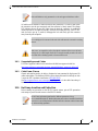
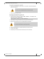
NOTE:
THIS HARDWARE, SOFTWARE OR TEST SUITE PRODUCT (“PRODUCT(S)”) AND ITS RELATED
DOCUMENTATION ARE PROVIDED BY MELLANOX TECHNOLOGIES “AS-IS” WITH ALL FAULTS OF ANY
KIND AND SOLELY FOR THE PURPOSE OF AIDING THE CUSTOMER IN TESTING APPLICATIONS THAT USE
THE PRODUCTS IN DESIGNATED SOLUTIONS. THE CUSTOMER'S MANUFACTURING TEST ENVIRONMENT
HAS NOT MET THE STANDARDS SET BY MELLANOX TECHNOLOGIES TO FULLY QUALIFY THE PRODUCT(S)
AND/OR THE SYSTEM USING IT. THEREFORE, MELLANOX TECHNOLOGIES CANNOT AND DOES NOT
GUARANTEE OR WARRANT THAT THE PRODUCTS WILL OPERATE WITH THE HIGHEST QUALITY. ANY
EXPRESS OR IMPLIED WARRANTIES, INCLUDING, BUT NOT LIMITED TO, THE IMPLIED WARRANTIES OF
MERCHANTABILITY, FITNESS FOR A PARTICULAR PURPOSE AND NONINFRINGEMENT ARE DISCLAIMED.
IN NO EVENT SHALL MELLANOX BE LIABLE TO CUSTOMER OR ANY THIRD PARTIES FOR ANY DIRECT,
INDIRECT, SPECIAL, EXEMPLARY, OR CONSEQUENTIAL DAMAGES OF ANY KIND (INCLUDING, BUT NOT
LIMITED TO, PAYMENT FOR PROCUREMENT OF SUBSTITUTE GOODS OR SERVICES; LOSS OF USE, DATA,
OR PROFITS; OR BUSINESS INTERRUPTION) HOWEVER CAUSED AND ON ANY THEORY OF LIABILITY,
WHETHER IN CONTRACT, STRICT LIABILITY, OR TORT (INCLUDING NEGLIGENCE OR OTHERWISE)
ARISING IN ANY WAY FROM THE USE OF THE PRODUCT(S) AND RELATED DOCUMENTATION EVEN IF
ADVISED OF THE POSSIBILITY OF SUCH DAMAGE.
Document Number: 3835
Mellanox Technologies
2

InfiniBand FDR Switch Platform Hardware User Manual
Mellanox Technologies
3
Table of Contents
Revision History . . . . . . . . . . . . . . . . . . . . . . . . . . . . . . . . . . . . . . . . . . . . . . . . . . . 9
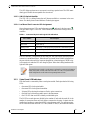
About this Manual . . . . . . . . . . . . . . . . . . . . . . . . . . . . . . . . . . . . . . . . . . . . . . . . . 10
Chapter 1 Overview . . . . . . . . . . . . . . . . . . . . . . . . . . . . . . . . . . . . . . . . . . . . . . . 12
1.1 Product Information. . . . . . . . . . . . . . . . . . . . . . . . . . . . . . . . . . . . . . . . . 12
1.1.1 Serial Number and Product Version Information . . . . . . . . . . . . . . . . . . . 12
1.1.2 Management Module MAC . . . . . . . . . . . . . .
. . . . . . . . . . . . . . . . . . . . . 13
1.1.3 Product Physical Specifications and Power. . . . . . . . . . . . . . . . . . . . . . . 13
1.2 Features List . . . . . . . . . . . . . . . . . . . . . . . . . . . . . . . . . . . . . . . . . . . . . . 15
1.3 InfiniBand FDR and FDR10 Overview. . . . . . . . . . . . . . . . . . . . . . . . . . . 15
1.4 Power Supply Redundancy. . . . . . . . . . . . . . . . . . . . . . . . . . . . . . . . . . . 15
1.4.1 1000W Power Supply Units . . . . . . . . . . . . . . . . . . . . . . . . . . . . . . . . . . . 16
1.4.2 1600W Power Supply Units . . . . . . . . . . . . . . . . . . . . . . . . . . . . . . . . . . . 16
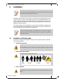
Chapter 2 Installation. . . . . . . . . . . . . . . . . . . . . . . . . . . . . . . . . . . . . . . . . . . . . . 18
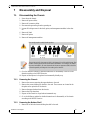
2.1 Installation Safety Warnings . . . . . . . . . . . . . . . . . . . . . . . . . . . . . . . . . . 18
2.2 Environmental and Safety Recommendations . . . . . . . . . . . . . . . . . . . . 22
2.3 Chassis Package Contents . . . . . . . . . . . . . . . . . . . . . . . . . . . . . . . . . . . 23
2.4 Leaf Package Contents. . . . . . . . . . . . . . . . . . . . . . . . . . . . . . . . . . . . . . 24
2.5 Spine Package Contents. . . . . . . . . . . . . . . . . . . . . . . . . . . . . . . . . . . . . 24
2.6 Management Package Contents. . . . . . . . . . . . . . . . . . . . . . . . . . . . . . . 24
2.7 Physical Installation. . . . . . . . . . . . . . . . . . . . . . . . . . . . . . . . . . . . . . . . . 24
2.7.1 ESD Connection . . . . . . . . . . . . . . . . . . . . . . . . . . . . . . . . . . . . . . . . . . . 25
2.7.2 Installing the Cable Holder. . . . . . . . . . . . . . . . . . . . . . . . . . . . . . . . . . . . 33
2.7.3 Installing the Chassis. . . . . . . . . . . . . . . . . . . . . . . . . . . . . . . . . . . . . . . . 35
2.7.4 Ground Connections . . . . . . . . . . . . . . . . . . . . . . . . . . . . . . . . . . . . . . . . 40
2.8 Power Connections . . . . . . . . . . . . . . . . . . . . . . . . . . . . . . . . . . . . . . . . . 41
2.8.1 Powering Up the Switch Platform. . . . . . . . . . . . . . . . . . . . . . . . . . . . . . . 41
2.9 InfiniBand QSFP Cable Installation. . . . . . . . . . . . . . . . . . . . . . . . . . . . . 42
2.9.1 Supported Approved Cables . . . . . . . . . . . . . . . . . . . . . . . . . . . . . . . . . . 43
2.9.2 Cable Power Classes. . . . . . . . . . . . . . . . . . .
. . . . . . . . . . . . . . . . . . . . . 43
2.10 Hot Swap Insertion and Extraction . . . . . . . . . . . . . . . . . . . . . . . . . . . . . 43
2.10.1 Power Supply Units. . . . . . . . . . . . . . . . . . . . . . . . . . . . . . . . . . . . . . . . . 44
2.10.2 Leaf Boards. . . . . . . . . . . . . . . . . . . . . . . . . . . . . . . . . . . . . . . . . . . . . . . 46
2.10.3 Spine Boards. . . . . . . . . . . . . . . . . . . . . . . . . . . . . . . . . . . . . . . . . . . . . . 49
2.10.4 Fan Modules . . . . . . . . . . . . . . . . . . . . . . . . . . . . . . . . . . . . . . . . . . . . . . 54
2.10.5 Management Module. . . . . . . . . . . . . . . . . . . . . . . . . . . . . . . . . . . . . . . . 56
2.10.6 Switch Shut-Down Procedures . . . . . . . . . . . . . . . . . . . . . . . . . . . . . . . . 59
Chapter 3 Interfaces. . . . . . . . . . . . . . . . . . . . . . . . . . . . . . . . . . . . . . . . . . . . . . . 60
3.1 LED Status Indicators . . . . . . . . . . . . . . . . . . . . . . . . . . . . . . . . . . . . . . . 60
3.1.1 Power Supply Unit LEDs . . . . . . . . . . . . . . . . . . . . . . . . . . . . . . . . . . . . . 60
3.1.2 Leaf Board LED Indicators. . . . . . . . . . . . . . . . . . . . . . . . . . . . . . . . . . . . 62
3.1.3 Spine Board LED Indicators. . . . . . . . . . . . . .
. . . . . . . . . . . . . . . . . . . . . 63
3.1.4 Spine Side Panel Display LED Indicators . . . .
. . . . . . . . . . . . . . . . . . . . 65
3.1.5 Management Module LED Indicators. .
. . . . . . . . . . . . . . . . . . . . . . . . . . 67

InfiniBand FDR Switch Platform Hardware User Manual
Mellanox Technologies
4
3.1.6 Port Connector Interfaces . . . . . . . . . . . . . . . . . . . . . . . . . . . . . . . . . . . . 68
3.2 Air Flow . . . . . . . . . . . . . . . . . . . . . . . . . . . . . . . . . . . . . . . . . . . . . . . . . . 69
3.3 QSFP Cable Power Budget Classification. . . . . . . . . . . . . . . . . . . . . . . . 69
3.4 Management Module Interfaces . . . . . . . . . . . . . . . . . . . . . . . . . . . . . . . 69
3.4.1 I2C . . . . . . . . . . . . . . . . . . . . . . . . . . . . . . . . . . . . . . . . . . . . . . . . . . . . . . 70
3.4.2 CONSOLE . . . . . . . . . . . . . . . . . . . . . . . . . . . . . . . . . . . . . . . . . . . . . . . . 70
3.4.3 MGT– Management. . . . . . . . . . . . . . . . . . . . . . . . . . . . . . . . . . . . . . . . . 70
3.4.4 USB . . . . . . . . . . . . . . . . . . . . . . . . . . . . . . . . . . . . . . . . . . . . . . . . . . . . . 70
3.4.5 Reset – RST. . . . . . . . . . . . . . . . . . . . . . . . . . . . . . . . . . . . . . . . . . . . . . . 70
Chapter 4 Chassis Power Up. . . . . . . . . . . . . . . . . . . . . . . . . . . . . . . . . . . . . . . . 72
4.1 Power Supply and Spine Board Indicator Status at Power ON. . . . . . . . 73
Chapter 5 Switch Management Tools. . . . . . . . . . . . . . . . . . . . . . . . . . . . . . . . . 74
5.1 InfiniBand Subnet Manager. . . . . . . . . . . . . . . . . . . . . . . . . . . . . . . . . . . 75
5.2 Fabric Inspector (Diagnostics). . . . . . . . . . . . . . . . . . . . . . . . . . . . . . . . . 75
5.3 Accessing the CPU via the Ethernet Connector . . . . . . . . . . . . . . . . . . . 75
5.4 Upgrading Software. . . . . . . . . . . . . . . . . . . . . . . . . . . . . . . . . . . . . . . . . 75
Chapter 6 Troubleshooting . . . . . . . . . . . . . . . . . . . . . . . . . . . . . . . . . . . . . . . . . 76
6.1 Power Supply Unit. . . . . . . . . . . . . . . . . . . . . . . . . . . . . . . . . . . . . . . . . . 76
6.2 Leaf Board. . . . . . . . . . . . . . . . . . . . . . . . . . . . . . . . . . . . . . . . . . . . . . . . 76
6.3 Management Module. . . . . . . . . . . . . . . . . . . . . . . . . . . . . . . . . . . . . . . . 77
6.4 Spine Board. . . . . . . . . . . . . . . . . . . . . . . . . . . . . . . . . . . . . . . . . . . . . . . 78
6.5 MLNX-OS® Software . . . . . . . . . . . . . . . . . . . . . . . . . . . . . . . . . . . . . . . 78
Chapter 7 Disassembly and Disposal. . . . . . . . . . . . . . . . . . . . . . . . . . . . . . . . . 79
7.1 Disassembling the Chassis . . . . . . . . . . . . . . . . . . . . . . . . . . . . . . . . . . . 79
7.1.1 Removing the Chassis. . . . . . . . . . . . . . . . . . . . . . . . . . . . . . . . . . . . . . . 79
7.1.2 Removing the Bottom Shelf . . . . . . . . . . . . . . . . . . . . . . . . . . . . . . . . . . . 79
7.2 Disposal. . . . . . . . . . . . . . . . . . . . . . . . . . . . . . . . . . . . . . . . . . . . . . . . . . 80
Appendix A Specification Data . . . . . . . . . . . . . . . . . . . . . . . . . . . . . . . . . . . . . . 81
A.1 EMI Certification . . . . . . . . . . . . . . . . . . . . . . . . . . . . . . . . . . . . . . . . . 83
A.2 Approved Cables . . . . . . . . . . . . . . . . . . . . . . . . . . . . . . . . . . . . . . . . 83
A.3 EMC Certifications . . . . . . . . . . . . . . . . . . . . . . . . . . . . . . . . . . . . . . . 83
Appendix B Thermal Threshold Definitions . . . . . . . . . . . . . . . . . . . . . . . . . . . 84
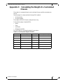
Appendix C Calculating the Weight of a Customized Chassis . . . . . . . . . . . . 85
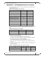
Appendix D Calculating the Power of a Chassis . . . . . . . . . . . . . . . . . . . . . . . 86
Appendix E QSFP Interface . . . . . . . . . . . . . . . . . . . . . . . . . . . . . . . . . . . . . . . . 88
Appendix F Replacement Parts Ordering Numbers . . . . . . . . . . . . . . . . . . . . . 91
Appendix G Safety Warnings (Multiple Languages) . . . . . . . . . . . . . . . . . . . . . 92
G.1 Nordic Countries Notices . . . . . . . . . . . . . . . . . . . . . . . . . . . . . . . . . . 92
G.2 Installation Safety Warnings (English) . . . . . . . . . . . . . . . . . . . . . . . . 92
G.3 (תירבע) הנקתהב תוחיטב תורהזא. . . . . . . . . . . . . . . . . . . . . . . . . . . . . . . 95
G.4 安裝安全性警告 (Chinese) . . . . . . . . . . . . . . . . . . . . . . . . . . . . . . . . . 99
G.5 Avertissements de sécurité pour l'installation (French) . . . . . . . . . . 102
G.6 Installation Sicherheitshinweise(German). . . . . . . . . . . . . . . . . . . . . 105
G.7 Advertencias de seguridad de instalación (Spanish) . . . . . . . . . . . . 109
G.8 Предупреждения по технике безопасности при установке (Russian) 112
G.9 Avertismente privind siguranţa la instalare (Romanian) . . . . . . . . . . 115
G.10 Sigurnosna upozorenja za instaliranje (Croatian). . . . . . . . . . . . . . . 119
G.11 Avvertenze di sicurezza per l’installazione (italiano) . . . . . . . . . . . . 122

InfiniBand FDR Switch Platform Hardware User Manual
Mellanox Technologies
5
G.12 Montaj Güvenlik Uyarıları (Türkçe). . . . . . . . . . . . . . . . . . . . . . . . . . 126
G.13 Japan VCCI Class A Statement . . . . . . . . . . . . . . . . . . . . . . . . . . . . 129

InfiniBand FDR Switch Platform Hardware User Manual
Mellanox Technologies
6
List of Tables
Table 1: Revision History of this User’s Manual. . . . . . . . . . . . . . . . . . . . . . . . . . . . . . . . . 9
Table 2: Reference Documents and Websites. . . . . . . . . . . . . . . . . . . . . . . . . . . . . . . . . 10
Table 3: OPNs for Power Supply Units . . . . . . . . . . . . . . . . . . . . . . . . . . . . . . . . . . . . . . 17
Table 4: Leaf Status LED. . . . . . . . . . . . . . . . . . . . . . . . . . . . . . . . . . . . . . . . . . . . . . . . . 62
Table 5: Bad Port LED Configurations. . . . . . . . . . . . . . . . . . . . . . . . . . . . . . . . . . . . . . . 62
Table 6: Connector Physical and Logical Link Indications
. . . . . . . . . . . . . . . . . . . . . . . . 63
Table 7: Spine Status LED. . . . . . . . . . . . . . . . . . . . . . . . . . . . . . . . . . . . . . . . . . . . . . . . 64
Table 8: Spine Fan Status LED . . . . . . . . . . . . . . . . . . . . . . . . . . . . . . . . . . . . . . . . . . . . 64
Table 9: Spine to Leaf IB Link Status. . . . . . . . . . . . . . . . . . . . . . . . . . . . . . . . . . . . . . . . 65
Table 10: Bad Port LED Configurations. . . . . . . . . . . . . . . . . . . . . . . . . . . . . . . . . . . . . . . 65
Table 11: LEDs Display for Normal Operation. . . . . . . . . . . . . . . . . . . . . . . . . . . . . . . . . . 66
Table 12: LEDs Display for Normal Operation. . . . . . . . . . . . . . . . . . . . . . . . . . . . . . . . . . 67
Table 13: Management Module PSU LED Configurations . . . . . . . . . . . . . . . . . . . . . . . . 68
Table 14: Management Module S.Fan LED Configurations . . . . . . . . . . . . . . . . . . . . . . . 68
Table 15: Management Module L.Fan LED Configurations . . . . . . . . . . . . . . . . . . . . . . . 68
Table 16: Management Module MASTER LED Configurations . . . . . . . . . . . . . . . . . . . . 68
Table 17: Switch Specification SX6512-[4N]R. . . . . . . . . . . . . . . . . . . . . . . . . . . . . . . . . . 81
Table 18: Switch System Weight Calculation. . . . . . . . . . . . . . . . . . . . . . . . . . . . . . . . . . . 85
Table 19: Power Consumption of Chassis Parts . . . . . . . . . . . . . . . . . . . . . . . . . . . . . . . . 86
Table 20: QSFP Cable Power Consumption . . . . . . . . . . . . . . . . . . . . . . . . . . . . . . . . . . . 86
Table 21: Calculating Total Switch System Power Consump
tion . . . . . . . . . . . . . . . . . . . 86
Table 22: InfiniBand QSFP Connector Pinout . . . . . . . . . . . . . . . . . . . . . . . . . . . . . . . . . . 88
Table 23: Replacement Parts Ordering Numbers . . . . . . . . . . . . . . . . . . . . . . . . . . . . . . . 91

InfiniBand FDR Switch Platform Hardware User Manual
Mellanox Technologies
7
List of Figures
Figure 1: Product Label . . . . . . . . . . . . . . . . . . . . . . . . . . . . . . . . . . . . . . . . . . . . . . . . . . 12
Figure 2: Product Label Tab Location . . . . . . . . . . . . . . . . . . . . . . . . . . . . . . . . . . . . . . . 13
Figure 3: Management Module MAC Address Location . . . . . . . . . . . . . . . . . . . . . . . . . 13
Figure 4: SX6512 Switch Views . . . . . . . . . . . . . . . . . . . . . . . . . . . . . . . . . . . . . . . . . . . . 14
Figure 5: Shelf Installation Kit Parts . . . . . . . . . . . . . . . . . . . . . . . . . . . . . . . . . . . . . . . . . 26
Figure 6: Chassis Installation Parts . . . . . . . . . . . . . . . . . . . . . . . . . . . . . . . . . . . . . . . . . 27
Figure 7: Shock Stickers . . . . . . . . . . . . . . . . . . . . . . . . . . . . . . . . . . . . . . . . . . . . . . . . . 28
Figure 8: Tilt Sticker . . . . . . . . . . . . . . . . . . . . . . . . . . . . . . . . . . . . . . . . . . . . . . . . . . . . . 28
Figure 9: Opening the Container . . . . . . . . . . . . . . . . . . . . . . . . . . . . . . . . . . . . . . . . . . . 29
Figure 10: Placement of Chassis in Rack . . . . . . . . . . . . . . . . . . . . . . . . . . . . . . . . . . . . . 30
Figure 11: Inserting the Caged Nuts for the Shelf . . . . . . . . . . . . . . . . . . . . . . . . . . . . . . . 30
Figure 12: Connect Rail Slide to Rack Vertical support . . . . . . . . . . . . . . . . . . . . . . . . . . . 31
Figure 13: Inserting the Caged Nuts for the Faceplate . . . . . . . . . . . . . . . . . . . . . . . . . . . 31
Figure 14: Chassis on Shelf with Filler Panel . . . . . . . . . . . . . . . . . . . . . . . . . . . . . . . . . . . 32
Figure 15: Cable Holders . . . . . . . . . . . . . . . . . . . . . . . . . . . . . . . . . . . . . . . . . . . . . . . . . . 33
Figure 16: Cable Holder Placement . . . . . . . . . . . . . . . . . . . . . . . . . . . . . . . . . . . . . . . . . . 34
Figure 17: Chassis Rails and Rail Slides . . . . . . . . . . . . . . .
. . . . . . . . . . . . . . . . . . . . . . . 35
Figure 18: Installing the Handles . . . . . . . . . . . . . . . . . . . . . . . . . . . . . . . . . . . . . . . . . . . . 36
Figure 19: Screw the Handles Onto the Chassis . . . . . . . . . . . . . . . . . . . . . . . . . . . . . . . . 36
Figure 20: The Rails are Already Connected Onto the Chassis
. . . . . . . . . . . . . . . . . . . . 37
Figure 21: Raising the Chassis Using a Mechanical Lift
. . . . . . . . . . . . . . . . . . . . . . . . . . 38
Figure 22: Put on the Rail Slide . . . . . . . . . . . . . . . . . . . . . . . . . . . . . . . . . . . . . . . . . . . . . 38
Figure 23: SX6512 Chassis on the Shelf . . . . . . . . . . . . . . . . . . . . . . . . . . . . . . . . . . . . . 39
Figure 24: Face Plate Mounting Bolt Locations . . . . . . . . . . . . . . . . . . . . . . . . . . . . . . . . . 39
Figure 25: Ground Connection . . . . . . . . . . . . . . . . . . . . . . . . . . . . . . . . . . . . . . . . . . . . . 40
Figure 26: Multiple Power Inlets – Electric Caution Notification . . . . . . . . . . . . . . . . . . . . . 41
Figure 27: Spine Module . . . . . . . . . . . . . . . . . . . . . . . . . . . . . . . . . . . . . . . . . . . . . . . . . . 42
Figure 28: Power Cord Numbering . . . . . . . . . . . . . . . . . . . . . . . . . . . . . . . . . . . . . . . . . . . 44
Figure 29: PSU Locations . . . . . . . . . . . . . . . . . . . . . . . . . . . . . . . . . . . . . . . . . . . . . . . . . 45
Figure 30: Power Supply . . . . . . . . . . . . . . . . . . . . . . . . . . . . . . . . . . . . . . . . . . . . . . . . . . 45
Figure 31: Leaf Board Numbering . . . . . . . . . . . . . . . . . . . . . . . . . . . . . . . . . . . . . . . . . . . 46
Figure 32: Ejector Handle . . . . . . . . . . . . . . . . . . . . . . . . . . . . . . . . . . . . . . . . . . . . . . . . . . 47
Figure 33: Leaf Release . . . . . . . . . . . . . . . . . . . . . . . . . . . . . . . . . . . . . . . . . . . . . . . . . . . 47
Figure 34: Intact vs Defected Signal Connectors . . . . . . . . . . . . . . . . . . . . . . . . . . . . . . . . 48
Figure 35: Intact vs Defected Power Pin Holders . . . . . . . . . . . . . . . . . . . . . . . . . . . . . . . . 48
Figure 36: Management Module Numbering . . . . . . . . . . . . . . . . . . . . . . . . . . . . . . . . . . . 50
Figure 37: Spine Board Extraction . . . . . . . . . . . . . . . . . . . . . . . . . . . . . . . . . . . . . . . . . . 50

InfiniBand FDR Switch Platform Hardware User Manual
Mellanox Technologies
8
Figure 38: Intact vs Defected Mechanics . . . . . . . . . . . . . . . . . . . . . . . . . . . . . . . . . . . . . . 52
Figure 39: Intact vs Defected Side Signal Connectors . . . . . . . . . . . . . . . . . . . . . . . . . . . . 52
Figure 40: Intact vs Defected Middle Signal Connectors . . . . . . . . . . . . . . . . . . . . . . . . . . 53
Figure 41: Intact vs Defected Power Pin Holders . . . . . . . . . . . . . . . . . . . . . . . . . . . . . . . . 53
Figure 42: Spine Board Insertion Caution . . . . . . . . . . . . . . . . . . . . . . . . . . . . . . . . . . . . . 53
Figure 43: Leaf Fan Locations on the Chassis . . . . . . . . . . . . . . . . . . . . . . . . . . . . . . . . . . 54
Figure 44: Leaf Fan Module Extraction . . . . . . . . . . . . . . . . . . . . . . . . . . . . . . . . . . . . . . . 55
Figure 45: Spine Fan Module . . . . . . . . . . . . . . . . . . . . . . . . . . . . . . . . . . . . . . . . . . . . . . . 55
Figure 46: Fan Status LED on the Spine Module . . . . . . . . . . . . . . . . . . . . . . . . . . . . . . . . 56
Figure 47: Management Module . . . . . . . . . . . . . . . . . . . . . . . . . . . . . . . . . . . . . . . . . . . . 57
Figure 48: Intact vs Defected Signal Connectors . . . . . . . . . . . . . . . . . . . . . . . . . . . . . . . . 57
Figure 49: Intact vs Defected Power Pin Holders . . . . . . . . . . . . . . . . . . . . . . . . . . . . . . . . 58
Figure 50: Power Supply Unit Status Indications . . . . . . . . . . . . . . . . . . . . . . . . . . . . . . . 60
Figure 51: PSU Cover On and Off . . . . . . . . . . . . . . . . . . . . . . . . . . . . . . . . . . . . . . . . . . 61
Figure 52: Leaf Board Led Indicators . . . . . . . . . . . . . . . . . . . . . . . . . . . . . . . . . . . . . . . . 62
Figure 53: Spine Status LEDs . . . . . . . . . . . . . . . . . . . . . . . . . . . . . . . . . . . . . . . . . . . . . . 64
Figure 54: Spine Side Panel Display Status Indications . . . . . . . . . . . . . . . . . . . . . . . . . . 66
Figure 55: Management Module Status Indications . . . . . . . . . . . . . . . . . . . . . . . . . . . . . 67
Figure 56: Management Module LEDs . . . . . . . . . . . . . . . . . . . . . . . . . . . . . . . . . . . . . . . . 67
Figure 57: Port Numbering . . . . . . . . . . . . . . . . . . . . . . . . . . . . . . . . . . . . . . . . . . . . . . . . . 69
Figure 58: Top and Bottom Ports . . . . . . . . . . . . . . . . . . . . . . . . . . . . . . . . . . . . . . . . . . . . 69
Figure 59: Management Module Interfaces . . . . . . . . . . . . . . . . . . . . . . . . . . . . . . . . . . . . 69
Figure 60: Reset Button . . . . . . . . . . . . . . . . . . . . . . . . . . . . . . . . . . . . . . . . . . . . . . . . . . . 71
Figure 61: Spine Side Panel Display Status Indications . . . . . . . . . . . . . . . . . . . . . . . . . . 73
Figure 62: Management Module Status Indications for Normal Operation . . . . . . . . . . . . 73
Figure 63: InfiniBand QSFP Connector Symbol . . . . . . . . . . . . . . . . . . . . . . . . . . . . . . . . . 89
Figure 64: QSFP Connector Male and Female Views . . . . . . . . . . . . . . . . . . . . . . . . . . . . 90

InfiniBand FDR Switch Platform Hardware User Manual
Mellanox Technologies
9
Revision History
Table 1 - Revision History of this User’s Manual
Revision Date Details
2.2
July 06,
2015 Updated:
• Section 2.3, “Chassis Package Contents,” on page 23
• Section G.13, “Japan VCCI Class A Statement,” on page 129
2.1 Feb 24, 2015 Updated:
• Table 12, “LEDs Display for Normal Operation,” on page 67 with master LED
status indicators
• Appendix A, “Specification Data,” on page 81 with FDR10 power numbers
and max heat output
• Appendix D, “Calculating the Power of a Chassis,” on page 86 with FDR10
power numbers
2.0 Nov 17, 2014 Updated:
• Section 1.4.2, “1600W Power Supply Units,” on page 16
• Section 2.7.1.3, “Container Mishandling,” on page 27
• Appendix A, “Specification Data,” on page 81
1.9 Oct 27, 2014 Updated:
• Max. Air Flow numbers in Appendix A, “Specification Data,” on page 81
• N+1 configuration in Section 1.4.2, “1600W Power Supply Units,” on page 16
1.8 July 18, 2014 Updated:
• Section 2.7.4, “Ground Connections,” on page 40
• Appendix A, “Specification Data,” on page 81
• Appendix D, “Calculating the Power of a Chassis,” on page 86
1.7 January, 2014 Rearranged document: Consolidated installation sections under Chapter 2,
“Installation,” on page 18; updated Chapter 1, “Overview,” on page 12;
and re-ordered sections).
Added:
• Figure 56, “Management Module LEDs,” on page 67
Updated:
• Section 1.4, “Power Supply Redundancy,” on page 15
• Section 2.7.1.5, “Installing the Shelf,” on page 29
• Section 2.7.2, “Installing the Cable Holder,” on page 33
• FDR note in Section 2.9, “InfiniBand QSFP Cable Installation,” on page 42
• Section 2.10, “Hot Swap Insertion and Extraction,” on page 43
• Section 7.1, “Disassembling the Chassis,” on page 79
• Table 17, “Switch Specification SX6512-[4N]R,” on page 81
• Appendix D, “Calculating the Power of a Chassis,” on page 86
1.6 June 2013 New graphics
Changed PSU input power numbers to match the chassis power numbers;
both are measured at AC voltage not the DC side.
Added filler panel
rearranged parts lists.
Add Graphic showing the chassis with the filler panels
New Safety warnings
1.5 October 2012 Added Warning for handles
1.4 September 2012 Added figure 23.
Added information regarding inserting the bottom spine first. Insert spines
from bottom to top.

InfiniBand FDR Switch Platform Hardware User Manual
Mellanox Technologies
10
About this Manual
This manual provides an overview of the SwitchX® based SX6512 modular InfiniBand
chassis switch, and guidelines for its operation.
Intended Audience
This manual is intended for users and system administrators responsible for installing
and setting up the chassis platform.
The manual assumes familiarity with the InfiniBand
®
architecture specification.
Related Documentation
The documentation set accompanying the QSFP Chassis InfiniBand Switch platform
includes the following:
Conventions
Throughout this manual, the name SX6512 and the terms chassis and switch are used to
describe the 216 port QSFP InfiniBand chassis, unless explicitly indicated otherwise.
1.3 August, 2012 Minor changes due to changes in container.
1.2 July, 2012 Fixed broken link.
1.1 July, 2012 Added figure to show use of 2nd type of mechanical lift
Added EMI explanation to Appendix
Added explanation to N+2 Power Numbers.
1.0 May, 2012 Initial release
Table 2 - Reference Documents and Websites
Document Name Description
InfiniBand Architecture Specification,
Vol. 1, Release 1.2.1
The InfiniBand Architecture Specification that is provided by
IBTA
Switch Product Release Notes For possible hardware issues see the switch support product
page.
This requires a customer support login. Look up the rele-
vant SwitchX®-based switch system/se
ries release note file.
Mellanox MLNX-OS® User Manual
for
VPI
This document contains information regarding configuring and
managing Mellanox Technologies SwitchX® switch platforms
listing all of the commands available through MLNX-OS with
explanations and examples.
Table 1 - Revision History of this User’s Manual
Revision Date Details

InfiniBand FDR Switch Platform Hardware User Manual
Mellanox Technologies
11
The following icons are used throughout this document to indicate information that is
important to the user.
Mellanox Part Numbering Legend
This symbol makes recommendations to the user.
This symbol indicates information that is helpful to the user.
This symbol indicates a situation that can potentially cause damage to hardware or
software.
Warning! This symbol indicates a situation that can potentially cause personal injury
and / or damage to hardware or software.
Place Field Decoder
M Mellanox Technologies
SX System Type SwitchX® Switch
PR Data Transfer Protocol (1, 2, 3, 4) = Ethernet (5, 6, 7, 8) = InfiniBand
G Module Generation 5, 6, 7, 8
FF Number of leafs 36, 18, 12, 06
C Data Rate B = 40Gb/s Ethernet
F = FDR, T = FDR10, Q = QDR, D = DDR
- Separator
P # Power Supplies N = N+N redundant
1=1PSU, 2=2PSUs, ...
R Chip Generation R – SwitchX®
S – SwitchX®-2

InfiniBand FDR Switch Platform Hardware User Manual
Mellanox Technologies
12
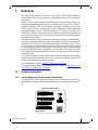
1 Overview
This User Manual provides an overview of the SX6512 QSFP Modular InfiniBand
Switch Platform (known in this document as ‘the chassis or switch’) and its operational
environment.
Mellanox SX6512 switch systems provide the highest
performing fabric solution by
delivering high bandwidth and low latency to Enterprise Data Centers (EDC), High-Per-
formance Computing (HPC) and Embedded environments. Networks built with the
SX6512 sys
tem can carry converged traffic with the combination of assured bandwidth
and granular quality of service. Built with Mellanox’s 5
th
generation SwitchX® VPI
switch device, SX6512 systems provide up to 56Gb/s full bidirectional bandwidth per
port. With up to 216 ports in a 9U high form factor, these systems are among the densest
switching systems available.
The switch platform comes pre-installed with
all necessary firmware for standard opera-
tion within an InfiniBand fabric and requires
an InfiniBand compliant Subnet Manager
running from one of the hosts or the management module of the switch system. The ini-
tial configuration procedure should be followed to initialize the switch before connecting
it to the network after which
normal operation can proceed. (See the installation guide
for details regarding the initial configuration.) Once connected to the network, the Sub-
net Management software automatically discove
rs and configures the fabric and begins
utilizing the switch.
The Mellanox Operating System (MLNX-OS®)
software package provides a subnet
manager and network management tools as well as connectivity software for servers and
storage, and is available on the Mellanox web site.
Basic installation is covered in
Chapter 2, “Installation” on page 18.
Hot-swapping components and hardware maintenance is covered in
Chapter 2.10, “Hot
Swap Insertion and Extraction” on page 43.
1.1 Product Information
1.1.1 Serial Number and Product Version Information
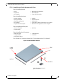
The serial number, GUID identifier and product version information are found on the
label attached to the pull-out tab below the Mellanox logo on the spine side of the chas-
sis.
Figure 1: Product Label
S/N: MT0806X01504
P/N: MSX6506-3R
GUID: 0002C9020027051C
Made in Israel
Rev:A1
MAC: 0002C9020040

InfiniBand FDR Switch Platform Hardware User Manual
Mellanox Technologies
13
The GUID is the System Image GUID according to the IB spec. It is burned on the board
which is in the chassis. All the boards and the management software look for this GUID
in addition to their own Node GUID.
Figure 2: Product Label Tab Location
1.1.2 Management Module MAC
Each management module has a label with its MAC address. See Figure 3 for the loca-
tion of this label.
Figure 3: Management Module MAC Address Location
1.1.3 Product Physical Specifications and Power
The switch ships in a minimum base configuration plus additional modules depending on
the chosen customer configuration. Optional modules included:
• Leaf boards
•
Management modules
• Spine boards
Here is the tab with
the product label
MGTCONSOLE
RST
I2C
MasterL.FANSS.FANSPSU
MAC
MAC address location

InfiniBand FDR Switch Platform Hardware User Manual
Mellanox Technologies
14
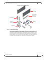
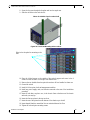
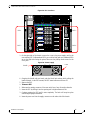
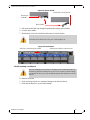
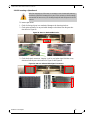
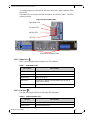
The following figure shows the connector and spine sides fully populated.
Figure 4: SX6512 Switch Views
FRONT SIDE ORCA SX6512
Spine Side
Up to 4 power supply units
12 leaf modules
2 management modules
4 leaf fan modules
6 spine modules
Connector Side

InfiniBand FDR Switch Platform Hardware User Manual
Mellanox Technologies
15
1.2 Features List
• 216 FDR (56Gb/s) InfiniBand ports in a 9U switch
• 24.2 Tb/s aggregate data switching capacity with ultra low latency
• IBTA 1.3 and 1.2.1 compliant
• SDR/DDR/QDR/FDR10/FDR link speed
• N+N power supply
• Congestion control
1
• Adaptive routing
1
• Port mirroring
1
• Chassis High Availability
• sMB High Availability
1.3 InfiniBand FDR and FDR10 Overview
The Mellanox SX6512 switch system supports FDR, standard InfiniBand data rate,
where each lane of a 4X port runs a bit rate of 14.0625Gb/s with a 64b/66b encoding,
resulting in an effective bandwidth of 54.54Gb/s. The FDR physical layer is an IBTA
specified physical layer using different block types, deskew mechanism and framing
rules.
The SX6512 switch also supports FDR10, a n
on-standard InfiniBand data rate, where
each lane of a 4X port runs a bit rate of 10.3125Gb/s with a 64b/66b encoding, resulting
in an effective bandwidth of 40Gb/s.
FDR10 supports 20% more bandwidth over regula
r QDR using the same QSFP cables/
connectors.
Both FDR and FDR10 support Forward Error Corre
ction (FEC), as described in IEEE
Std 802.3ap-2007 (Amendment to IEEE Std 802.3-2005) chapter 74.
1.4 Power Supply Redundancy
The SX6512 platform comes standard with four power supplies and has two order
options:
• SX6512-4R - N+1 redundancy
• SX6512-NR - N+N redundancy
1. Features for a future release.
FDR and FDR10 are only guaranteed to work with approved Mellanox cables.
FDR10 is only guaranteed to work with approved Mellanox ConnectX-3 adapters.

InfiniBand FDR Switch Platform Hardware User Manual
Mellanox Technologies
16
1.4.1 1000W Power Supply Units
The 1000W power supply units (PSUs) deliver 1000W at 48V. The AC source to each
PSU must be able to provide 1176.5W in order to output 1000W in DC.
With 1000W PSUs the only redundancy option is
N+1. In this configuration 1PSU can
be extracted without bringing down the system. When using the 1000W PSUs, the mini-
mum complement of PSUs at start-up is
4 and the chassis will continue to run at full
capacity with only 3 PSUs.
1.4.2 1600W Power Supply Units
The 1600W power supply units (PSUs) deliver 1600W at 48V. The AC source to each
PSU must be able to provide 1882.4W in order to output 1600W in DC.
When using the 1600W PSUs, the minimum complement
of PSUs which allows the
chassis to run at full capacity is 2.
The 1600W PSUs can implement the following two redundancy options:
• No redundancy (combined mode)
•
N+1 configuration (ps-redundant mode)
When supplied from a single 220V power grid, the
chassis supports up to 2 redundant units.
Thereby, the minimum required number of PSUs equals 2. When supplied by a single 110V
power grid, the number of redundant power supplies is only 1.
• N+N configuration (grid-redundant mode)
The chassis PSUs are fed from two power grids for high availability
. The second power grid
can be supplied by any of the following:
• a backup power supply grid
• a generator
• a battery backup system
• any combination of the above
Connecting 2 power supplies to one power supply grid
and the remaining 2 power supplies to
a secondary power supply grid will create N+N redundancy. This is High Availability. Under
these conditions should a power grid fail (an electric company power failure or blackout for
example) power grid High Availability will continue to keep the chassis running at full capac-
ity through the secondary or backup power supply grid.
With N+N optional PSU grid redundancy the chassis can run on 1/2 of the full complement of
PSU
s. N+N allows the chassis to run on 2 PSUs supplied from one power grid while 2 are
connected to a second power grid.
N+N redundancy ONLY works with a supply voltage of 220V.
With power grid A charged with current and power grid B not charged there is only
grid redundancy and not PSU redundancy.

InfiniBand FDR Switch Platform Hardware User Manual
Mellanox Technologies
17
When the power drops below the required minimum due to power supply failure,
MLNX-OS® may power down some leafs. If this happens it may be necessary to reboot
the chassis once the defective PSU has been replaced. Two simple ways to reboot is to
use the reboot command in the CLI or reboot through the WebUI.
The form is identical between the two PSU types while the 1000W PSU weighs 0.3kg
more than the 1600W
PSU.
Table 3 - OPNs for Power Supply Units
OPN
PSU
Wattage
Description
MTP005001 1000W Supplies N+1 redundancy
MTP006002 1600W Supplies N+N redundancy for all switch chassis at 220 Volts

InfiniBand FDR Switch Platform Hardware User Manual
Mellanox Technologies
18
2Installation
Installation and initialization of the chassis is a simple process requiring attention to the
normal mechanical, power, and thermal precautions for rack-mounted equipment. Your
chassis comes only with the power supplies and fans pre-installed. The rest of the open-
ings are populated with blanks. All of the leafs, sp
ines, and management modules come
shipped in a separate package.
The chassis requires initial configuration
to get the chassis and Fabric management up
and running through remote management. See the Installation Guide that is packed in the
box for the instructions to make the initial configuration.
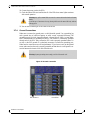
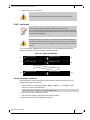
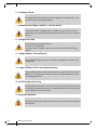
2.1 Installation Safety Warnings
These safety warnings are in English. For French, German, Spanish, Russian, and Roma-
nian see the Appendixes.
1. Installation Instructions
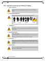
2. Bodily Injury Due to Weight
3. Heavy Equipment
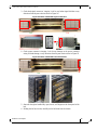
This chassis can be installed in standard 19” racks that have depths between 65cm and
80cm between the vertical supports of the rack.
This unit is intended for installation in a Restricted Access Location. A restricted
access area can be accessed only through the use of a special tool, lock and key, or
other means of security.
Read all installation instructions before connecting the equipment to the power source.
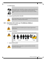
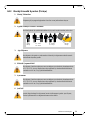
Use enough people to safely lift this product.
This equipment is very heavy and should be moved using a mechanical lift to avoid
injuries.
<40 lbs
<18 kgs
40 - 70 lbs
18 - 32 kgs
70 - 121 lbs
32 - 55 kgs
>121 lbs
>55 kgs

InfiniBand FDR Switch Platform Hardware User Manual
Mellanox Technologies
19
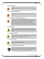
4. Installation in Restricted Access Location
5. Risk of Electric Shock!
6. Over-temperature
7. Stacking the Chassis
8. Redundant Power Supply Connection - Electrical Hazard
9. Double Pole/Neutral Fusing
10. Multiple Power Inlets ,
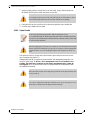
This unit is intended for installation in a Restricted Access Location.
Risk of Electric Shock!
With the fan module removed power pins are accessible within the module cavity.
DO NOT insert tools or body parts into the fan module cavity.
This equipment should not be operated in an area with an ambient temperature exceed-
ing the maximum recommended: 45°C (113°F). Moreover, to guarantee proper air
flow, allow at least 8cm (3 inches) of clearance around the ventilation openings.
The chassis should not be stacked on any other equipment. If the chassis falls, it can
cause bodily injury and equipment damage.
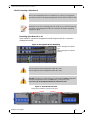
This product includes a redundant power or a blank in its place. In case of a blank
power supply, do not operate the product with the blank cover removed or not securely
fastened.
This system has double pole/neutral fusing. Remove all power cords before opening
the cover of this product or touching any internal parts.
Risk of electric shock and energy hazard.
The PSUs are all independent.
Disconnect all power supplies to ensure a powered down state inside of the switch
platform.

InfiniBand FDR Switch Platform Hardware User Manual
Mellanox Technologies
20
11. During Lightning - Electrical Hazard
12. Copper InfiniBand Cable Connecting/Disconnecting
13. Rack Mounting and Servicing
14. Equipment Installation
15. Equipment Disposal
16. Local and National Electrical Codes
17. Installation Codes
During periods of lightning activity, do not work on the equipment or connect or dis-
connect cables.
Copper InfiniBand cables are heavy and not flexible, as such they should be carefully
attached to or detached from the connectors. Refer to the cable manufacturer for spe-
cial warnings/instructions.
When this product is mounted or serviced in a rack, special precautions must be taken
to ensure that the system remains stable. In general you should fill the rack with equip-
ment starting from the bottom to the top.
This equipment should be installed, replaced, and/or serviced only by trained and qual-
ified personnel.
Disposal of this equipment should be in accordance to all national laws and regula-
tions.
This equipment should be installed in compliance with local and national electrical
codes.
This device must be installed according to the latest version of the country
national electrical codes. For North America, equipment must be installed in
accordance to the applicable requirements in the US National Electrical Code
and the Canadian Electrical Code.
La pagina si sta caricando...
La pagina si sta caricando...
La pagina si sta caricando...
La pagina si sta caricando...
La pagina si sta caricando...
La pagina si sta caricando...
La pagina si sta caricando...
La pagina si sta caricando...
La pagina si sta caricando...
La pagina si sta caricando...
La pagina si sta caricando...
La pagina si sta caricando...
La pagina si sta caricando...
La pagina si sta caricando...
La pagina si sta caricando...
La pagina si sta caricando...
La pagina si sta caricando...
La pagina si sta caricando...
La pagina si sta caricando...
La pagina si sta caricando...
La pagina si sta caricando...
La pagina si sta caricando...
La pagina si sta caricando...
La pagina si sta caricando...
La pagina si sta caricando...
La pagina si sta caricando...
La pagina si sta caricando...
La pagina si sta caricando...
La pagina si sta caricando...
La pagina si sta caricando...
La pagina si sta caricando...
La pagina si sta caricando...
La pagina si sta caricando...
La pagina si sta caricando...
La pagina si sta caricando...
La pagina si sta caricando...
La pagina si sta caricando...
La pagina si sta caricando...
La pagina si sta caricando...
La pagina si sta caricando...
La pagina si sta caricando...
La pagina si sta caricando...
La pagina si sta caricando...
La pagina si sta caricando...
La pagina si sta caricando...
La pagina si sta caricando...
La pagina si sta caricando...
La pagina si sta caricando...
La pagina si sta caricando...
La pagina si sta caricando...
La pagina si sta caricando...
La pagina si sta caricando...
La pagina si sta caricando...
La pagina si sta caricando...
La pagina si sta caricando...
La pagina si sta caricando...
La pagina si sta caricando...
La pagina si sta caricando...
La pagina si sta caricando...
La pagina si sta caricando...
La pagina si sta caricando...
La pagina si sta caricando...
La pagina si sta caricando...
La pagina si sta caricando...
La pagina si sta caricando...
La pagina si sta caricando...
La pagina si sta caricando...
La pagina si sta caricando...
La pagina si sta caricando...
La pagina si sta caricando...
La pagina si sta caricando...
La pagina si sta caricando...
La pagina si sta caricando...
La pagina si sta caricando...
La pagina si sta caricando...
La pagina si sta caricando...
La pagina si sta caricando...
La pagina si sta caricando...
La pagina si sta caricando...
La pagina si sta caricando...
La pagina si sta caricando...
La pagina si sta caricando...
La pagina si sta caricando...
La pagina si sta caricando...
La pagina si sta caricando...
La pagina si sta caricando...
La pagina si sta caricando...
La pagina si sta caricando...
La pagina si sta caricando...
La pagina si sta caricando...
La pagina si sta caricando...
La pagina si sta caricando...
La pagina si sta caricando...
La pagina si sta caricando...
La pagina si sta caricando...
La pagina si sta caricando...
La pagina si sta caricando...
La pagina si sta caricando...
La pagina si sta caricando...
La pagina si sta caricando...
La pagina si sta caricando...
La pagina si sta caricando...
La pagina si sta caricando...
La pagina si sta caricando...
La pagina si sta caricando...
La pagina si sta caricando...
La pagina si sta caricando...
La pagina si sta caricando...
La pagina si sta caricando...
-
 1
1
-
 2
2
-
 3
3
-
 4
4
-
 5
5
-
 6
6
-
 7
7
-
 8
8
-
 9
9
-
 10
10
-
 11
11
-
 12
12
-
 13
13
-
 14
14
-
 15
15
-
 16
16
-
 17
17
-
 18
18
-
 19
19
-
 20
20
-
 21
21
-
 22
22
-
 23
23
-
 24
24
-
 25
25
-
 26
26
-
 27
27
-
 28
28
-
 29
29
-
 30
30
-
 31
31
-
 32
32
-
 33
33
-
 34
34
-
 35
35
-
 36
36
-
 37
37
-
 38
38
-
 39
39
-
 40
40
-
 41
41
-
 42
42
-
 43
43
-
 44
44
-
 45
45
-
 46
46
-
 47
47
-
 48
48
-
 49
49
-
 50
50
-
 51
51
-
 52
52
-
 53
53
-
 54
54
-
 55
55
-
 56
56
-
 57
57
-
 58
58
-
 59
59
-
 60
60
-
 61
61
-
 62
62
-
 63
63
-
 64
64
-
 65
65
-
 66
66
-
 67
67
-
 68
68
-
 69
69
-
 70
70
-
 71
71
-
 72
72
-
 73
73
-
 74
74
-
 75
75
-
 76
76
-
 77
77
-
 78
78
-
 79
79
-
 80
80
-
 81
81
-
 82
82
-
 83
83
-
 84
84
-
 85
85
-
 86
86
-
 87
87
-
 88
88
-
 89
89
-
 90
90
-
 91
91
-
 92
92
-
 93
93
-
 94
94
-
 95
95
-
 96
96
-
 97
97
-
 98
98
-
 99
99
-
 100
100
-
 101
101
-
 102
102
-
 103
103
-
 104
104
-
 105
105
-
 106
106
-
 107
107
-
 108
108
-
 109
109
-
 110
110
-
 111
111
-
 112
112
-
 113
113
-
 114
114
-
 115
115
-
 116
116
-
 117
117
-
 118
118
-
 119
119
-
 120
120
-
 121
121
-
 122
122
-
 123
123
-
 124
124
-
 125
125
-
 126
126
-
 127
127
-
 128
128
-
 129
129


Mellanox Technologies MSX6512-4R Hardware User Manual
- Tipo
- Hardware User Manual
- Questo manuale è adatto anche per
in altre lingue
- English: Mellanox Technologies MSX6512-4R
- română: Mellanox Technologies MSX6512-4R
Documenti correlati
-
Mellanox Technologies SX6005 Manuale utente
-
Mellanox Technologies Switch-IB Manuale utente
-
-
-
-
-
Altri documenti
-
Gold Note PSU-5 Manuale utente
-
IFM DF2208 Istruzioni per l'uso
-
Tyan Thunder S4987 Manuale utente
-
Tyan Transport GT26-B4987 Manuale utente
-
-
Allied Telesis AT-PWR01 Guida d'installazione
-
 Leaf Aptus-II Guida d'installazione
-
 NetShelter AR1000A Manuale utente
-
Allied Telesis AT-9900s Manuale utente

