IMG STAGELINE DIB-100 Manuale utente

Tipo
Manuale utente
DIB-100
Bestellnummer 0241140
© MONACOR INTERNATIONAL
All rights reserved
A-0539.99.05.04.2023
MONACOR INTERNATIONAL GmbH & Co. KG
Zum Falsch 36, 28307 Bremen
Germany
Importer: Epic Audio Ltd, Unit 9 Apollo Park
Station road, Long Buckby, NN6 7PF
United Kingdom, Company Registration: 13878247
THE AUDIO COMPANY THE AUDIO COMPANY THE AUDIO COMPANY THE AUDIO COMPANY THE AUDIO COMPANY THE AUDIO COMPANY THE AUDIO COMPANY THE AUDIO COMPANY
DI B-100
0dB –40–20
PAR. OUT
UNBAL . 50kΩ
INPUT ATT.
GROUND LIFTOUTPUT
BAL. 600Ω OFF ON
PROFESSIONAL
GUITAR AMPLIFI ER
GAIN 1
010
OVERDRIVE CHANNEL
GAIN 2
INPUT
CONTOUR
GAIN
SELECT
1
2
BASS
010
MIDDLE
010
TREBLE
010
LEVEL
010
LEVEL
010
BASS
010
MIDDLE
010
TREBLE
010
REVERB
010
VOLUME
010
MIN. 8 Ω
PHONES
NORMAL CHANNEL
CHANNEL
SELECT
MASTER
POWER
010 010
12-INPUT MIXING CONSOLE
AUX RTN1 AUX RTN2 AUX SEND MAIN OUT
TAPE IN
CH 1CH2 CH 3CH4 CH 5/6 CH 7/8 CH9/10 CH11/12
5/6 7/8 9/10 11/12
LINE LINE LINE LINE
HIGH
AUX1
AUX RTN1 AUX RTN2
LEVEL
HIGH
AUX1
HIGH
AUX1
HIGH
AUX1
HIGH
AUX1
HIGH
AUX1
HIGH
AUX1
HIGH
AUX1
PHANTOM POWER
POWER
PHONES
LEFT RIGHT
LR
C
010
5
-15 +15
0
-15 +15
0
010
5
010
5
GAIN
LOW
AUX2
PAN
10
0
5
+20
U
10
0
5
+20
U
10
0
5
+20
U
10
0
5
+20
U
10
0
5
+20
U
10
0
5
+20
U
10
0
5
+20
U
10
0
5
+20
U
10
0
5
+10
U
10
0
5
+10
U
010
5
010
5
010
5
LR
C
010
5
-15 +15
0
-15 +15
0
010
5
010
5
GAIN
LOW
AUX2
PAN
LR
C
010
5
-15 +15
0
-15 +15
0
010
5
010
5
GAIN
LOW
AUX2
PAN
LR
C
010
5
-15 +15
0
-15 +15
0
010
5
010
5
GAIN
LOW
AUX2
PAN
LR
C
010
5
-15 +15
0
-15 +15
0
010
5
010
5
GAIN
LOW
AUX2
BAL
LR
C
010
5
-15 +15
0
-15 +15
0
010
5
010
5
GAIN
LOW
AUX2
BAL
LR
C
010
5
-15 +15
0
-15 +15
0
010
5
LOW
AUX2
BAL
LR
C
010
5
-15 +15
0
-15 +15
0
010
5
LOW
AUX2
BAL
TAPE OUT
L
R
L
R
1
2
L
R
L
R
L
R
L
R
L
R
L
R
L
R
MIC MIC MIC MIC
LINE
INSER T
LINE
INSER T
LINE
INSER T
LINE
INSER T
+22
+10
+7
+4
+2
0
–2
–4
–7
–10
–20
–30
CLIP
LR1234
Musikinstrument DI-Box
Mischpult Instrumentenverstärker
DI-Box
Diese Anleitung richtet sich an Benutzer
mit Grundkenntnissen in der Audiotechnik.
Bitte lesen Sie die Anleitung vor dem Be-
trieb gründlich durch und heben Sie sie für
ein späteres Nachlesen auf.
1 Übersicht
2
3 4 5
1
DIB-100
PAR. OUT
UNBAL. 50 kΩ
INPUT
OUTPUT
BAL. 600Ω
GROUND LIFT
OFF ON
0 dB – 40–20
ATT.
1 symmetrischer Ausgang (XLR)
2 Groundlift-Schalter zum Trennen der Masse-
verbindung zwischen dem Eingang (3) und
dem Ausgang (1)
3 asymmetrischer Eingang (6,3-mm-Klinke)
4 asym. Durchschleifausgang (6,3-mm-Klinke):
hier kann das durchgeschleifte Eingangssignal
der Buchse (3) abgenommen werden
5 Schalter „ATT.“ zum Abschwächen des Ein-
gangssignals
2 Wichtige Hinweise
Das Produkt entspricht allen relevanten Richt-
linien der EU und trägt deshalb das -Zeichen.
Verwenden Sie das Produkt nur im Innenbereich
und schützen Sie es vor Tropf- und Spritzwasser
sowie vor hoher Luftfeuchtigkeit. Der zulässige
Einsatztemperaturbereich beträgt 0 – 40 °C.
Position „−20“ oder, bei sehr hohen Signalen, in
die Position „−40“ stellen.
4.2 Symmetrischen Ausgang anschließen
Das symmetrische Ausgangssignal steht am XLR-
Ausgang (1) zur Verfügung. Den Ausgang über
ein symmetrisches Kabel an einen hochempfind-
lichen Eingang eines Mischpultes (z. B. Mikrofon-
eingang) anschließen.
4.3 Durchschleifausgang nutzen
Soll das Instrumentensignal auch gleichzei-
tig auf einen Verstärker gegeben werden, den
Verstärker eingang an die Buchse „PAR. OUT“ (4)
anschließen (siehe Abb. unten). Hier liegt direkt
das vom Instrument kommende Signal an.
Achtung! Der Durchschleifausgang ist nicht
zum Anschluss von Lautsprechern geeignet.
Überlastungsgefahr!
4.4 Groundlift-Schalter
Steht der Groundlift-Schalter (2) in der Posi-
tion „OFF“, ist die Masse des asymmetrischen
Eingangs (3) mit der Masse des symmetrischen
Ausgangs (1) verbunden. Diese Schalterstellung
sollte zuerst gewählt werden. Tritt jedoch eine
Brummschleife auf, den Schalter in die Position
„ON“ stellen. Die Masse zwischen dem Ein- und
Ausgang ist dann aufgetrennt (galvanische Tren-
nung).
5 Technische Daten
Frequenzbereich: . . . . . 15 – 30 000 Hz, ±0 dB
Abschwächung des
Eingangsignals: . . . . . . . 0 dB, 20 dB, 40 dB
Eingang
1 × 6,3-mm-Klinke: . . 50 kΩ, asymmetrisch
Ausgänge
1 × 6,3-mm-Klinke: . . Durchschleifausgang,
asymmetrisch
1 × XLR: . . . . . . . . . . . 600 Ω, symmetrisch
Übersetzungsverhältnis: 10 : 1
Einsatztemperatur: . . . . 0 – 40 °C
Abmessungen: . . . . . . . 74 × 45 × 130 mm
Gewicht: . . . . . . . . . . . . 560 g
Änderungen vorbehalten.
Säubern Sie das Produkt nur mit einem trocke-
nen, weichen Tuch, niemals mit Wasser oder
Chemikalien.
Wird das Produkt falsch verwendet oder nicht
fachgerecht repariert, kann keine Haftung für
daraus resultierende Sach- oder Personenschä-
den und keine Garantie für das Produkt über-
nommen werden.
Soll das Produkt endgültig aus dem Be-
trieb genommen werden, entsorgen Sie
es gemäß den örtlichen Vorschriften.
3 Einsatzmöglichkeiten
Die DI-Box (Direct Injection) DIB-100 dient zum
optimalen Anschluss eines Musikinstruments
mit hochohmigem, asymmetrischen Ausgang an
einen niederohmigen, symmetrischen Eingang
eines Mischpults (siehe Abb. unten). Durch die
symmetrische Verbindung zum Mischpult lassen
sich auch bei langen Anschlussleitungen Störein-
strahlungen vermeiden.
Hohe Signalpegel können mit dem Abschwä-
cher reduziert und an den Mischpulteingang an-
gepasst werden. Dadurch lässt sich die DI-Box
auch direkt an den Lautsprecherausgang eines
Instrumentenverstärkers (z. B. Gitarrenverstärker)
anschließen. Die Klangbeeinflussung des Signals
durch den Verstärker bleibt somit erhalten.
4 Inbetriebnahme
Die DI-Box benötigt keine Stromversorgung.
4.1 Asymmetrischen Eingang anschließen
An die Eingangsbuchse „INPUT“ (3) den Ausgang
des Musikinstruments anschließen. Alternativ
kann die Eingangsbuchse auch mit dem Laut-
sprecherausgang eines Instrumentenverstärkers
verbunden werden.
Vorsicht! Lautsprecherausgänge von Verstär-
kern, die in Brückenschaltung arbeiten, nicht
anschließen, weil diese durch die DI-Box kurz-
geschlossen werden.
Steht der Schalter „ATT.“ (5) ganz links auf Posi-
tion „0 dB“, wird der Pegel das Eingangssignals
nicht abgeschwächt. Treten am nachfolgenden
Mischpult Verzerrungen auf, den Schalter in die
Deutsch
© MONACOR INTERNATIONAL
All rights reserved
A-0539.99.05.04.2023
MONACOR INTERNATIONAL GmbH & Co. KG
Zum Falsch 36, 28307 Bremen
Germany
Importer: Epic Audio Ltd, Unit 9 Apollo Park
Station road, Long Buckby, NN6 7PF
United Kingdom, Company Registration: 13878247
THE AUDIO COMPANY THE AUDIO COMPANY THE AUDIO COMPANY THE AUDIO COMPANY THE AUDIO COMPANY THE AUDIO COMPANY THE AUDIO COMPANY THE AUDIO COMPANY
DI B-100
0dB –40–20
PAR. OUT
UNBAL . 50kΩ
INPUT ATT.
GROUND LIFTOUTPUT
BAL. 600Ω OFF ON
PROFESSIONAL
GUITAR AMPLIFI ER
GAIN 1
010
OVERDRIVE CHANNEL
GAIN 2
INPUT
CONTOUR
GAIN
SELECT
1
2
BASS
010
MIDDLE
010
TREBLE
010
LEVEL
010
LEVEL
010
BASS
010
MIDDLE
010
TREBLE
010
REVERB
010
VOLUME
010
MIN. 8 Ω
PHONES
NORMAL CHANNEL
CHANNEL
SELECT
MASTER
POWER
010 010
12-INPUT MIXING CONSOLE
AUX RTN1 AUX RTN2 AUX SEND MAIN OUT
TAPE IN
CH 1CH2 CH 3CH4 CH 5/6 CH 7/8 CH9/10 CH11/12
5/6 7/8 9/10 11/12
LINE LINE LINE LINE
HIGH
AUX1
AUX RTN1 AUX RTN2
LEVEL
HIGH
AUX1
HIGH
AUX1
HIGH
AUX1
HIGH
AUX1
HIGH
AUX1
HIGH
AUX1
HIGH
AUX1
PHANTOM POWER
POWER
PHONES
LEFT RIGHT
LR
C
010
5
-15 +15
0
-15 +15
0
010
5
010
5
GAIN
LOW
AUX2
PAN
10
0
5
+20
U
10
0
5
+20
U
10
0
5
+20
U
10
0
5
+20
U
10
0
5
+20
U
10
0
5
+20
U
10
0
5
+20
U
10
0
5
+20
U
10
0
5
+10
U
10
0
5
+10
U
010
5
010
5
010
5
LR
C
010
5
-15 +15
0
-15 +15
0
010
5
010
5
GAIN
LOW
AUX2
PAN
LR
C
010
5
-15 +15
0
-15 +15
0
010
5
010
5
GAIN
LOW
AUX2
PAN
LR
C
010
5
-15 +15
0
-15 +15
0
010
5
010
5
GAIN
LOW
AUX2
PAN
LR
C
010
5
-15 +15
0
-15 +15
0
010
5
010
5
GAIN
LOW
AUX2
BAL
LR
C
010
5
-15 +15
0
-15 +15
0
010
5
010
5
GAIN
LOW
AUX2
BAL
LR
C
010
5
-15 +15
0
-15 +15
0
010
5
LOW
AUX2
BAL
LR
C
010
5
-15 +15
0
-15 +15
0
010
5
LOW
AUX2
BAL
TAPE OUT
L
R
L
R
1
2
L
R
L
R
L
R
L
R
L
R
L
R
L
R
MIC MIC MIC MIC
LINE
INSER T
LINE
INSER T
LINE
INSER T
LINE
INSER T
+22
+10
+7
+4
+2
0
–2
–4
–7
–10
–20
–30
CLIP
LR1234
Instrument amplifierMixer
DI BoxMusical
instrument
DI Box
These instructions are intended for users
with basic knowledge of audio technology.
Please read these instructions carefully prior
to operation and keep them for later ref-
erence.
1 Overview
2
3 4 5
1
DIB-100
PAR. OUT
UNBAL. 50 kΩ
INPUT
OUTPUT
BAL. 600Ω
GROUND LIFT
OFF ON
0 dB – 40–20
ATT.
1 Balanced output (XLR)
2 Groundlift switch for separating the ground
connection between the input (3) and the
output (1)
3 Unbalanced input (6.3 mm jack)
4 Unbalanced feedthrough output (6.3 mm jack);
at this jack, the fed-through input signal of
jack(3) can be picked up
5 Switch “ATT.” for attenuating the input signal
2 Important Notes
The product corresponds to all relevant directives
of the EU and is therefore marked with .
The product corresponds to the relevant UK legis-
lation and is therefore marked with UKCA.
distortions occur on the following mixer, set the
switch to position “−20” or, in case of very high
signals, to position “−40”.
4.2 Connecting the balanced output
The balanced output signal is available at the XLR
output (1). Connect the output via a balanced
cable to a highly sensitive input of a mixer (e. g.
microphone input).
4.3 Using the feedthrough output
For feeding the instrument signal simultaneously
to an amplifier, connect the amplifier input to the
jack “PAR. OUT” (4) [see fig. below]. This is where
the signal coming from the instrument is directly
applied.
Attention! The feedthrough output is not suit-
able for connecting speakers. Risk of overload!
4.4 Groundlift switch
If the groundlift switch (2) is in “OFF” position,
the ground of the unbalanced input (3) is con-
nected to the ground of the balanced output(1).
This switch position should be chosen first. How-
ever, in case of hum loops, set the switch to “ON”
position. Then the ground between input and
output is separated (galvanic separation).
5 Specifications
Frequency range: . . . . . 15 to 30 000 Hz, ±0 dB
Attenuation of
the input signal: . . . . . . 0 dB, 20 dB, 40 dB
Input
1 × 6.3 mm jack: . . . . . 50 kΩ, unbalanced
Outputs
1 × 6.3 mm jack: . . . . . feedthrough output,
unbalanced
1 × XLR: . . . . . . . . . . . 600 Ω, balanced
Transmission ratio: . . . . 10 : 1
Ambient temperature: . 0 – 40 °C
Dimensions: . . . . . . . . . 74 × 45 × 130 mm
Weight: . . . . . . . . . . . . 560 g
Subject to technical modification.
The product is suitable for indoor use only.
Protect it against dripping water, splash water
and high air humidity. The admissible ambient
temperature range is 0 – 40 °C.
For cleaning only use a dry, soft cloth; never use
water or chemicals.
No guarantee claims for the product and no
liability for any resulting personal damage or
material damage will be accepted if the product
is not correctly used or not expertly repaired.
If the product is to be put out of opera-
tion definitively, dispose of the product
in accordance with local regulations.
3 Applications
The DI Box (Direct Injection) DIB-100 has been
designed for optimum connection of a musical
instrument with unbalanced, high-impedance
output to a balanced, low-impedance input of a
mixer (see fig. below). Due to the balanced con-
nection to the mixer, interferences can be pre-
vented even in case of long connection cables.
High signal levels can be reduced with the
attenuator and be matched to the mixer input.
Thus, the DI Box can also be directly connected
to the speaker output of an instrument amplifier
(e. g. guitar amplifier). Consequently, the effect
of the amplifier on the sound of the signal is
maintained.
4 Setting into Operation
The DI Box does not require a power supply.
4.1 Connecting the unbalanced input
Connect the output of the musical instrument
to the input jack “INPUT” (3). Alternatively, the
input jack can also be connected to the speaker
output of an instrument amplifier.
Caution! Never connect speaker outputs of
amplifiers operating in bridge circuit; the DI Box
will short-circuit them.
If the switch “ATT.” (5) is at the left stop at “0 dB”,
the level of the input signal is not attenuated. If
DIB-100
Order Number 0241140
English
© MONACOR INTERNATIONAL
All rights reserved
A-0539.99.05.04.2023
MONACOR INTERNATIONAL GmbH & Co. KG
Zum Falsch 36, 28307 Bremen
Germany
Importer: Epic Audio Ltd, Unit 9 Apollo Park
Station road, Long Buckby, NN6 7PF
United Kingdom, Company Registration: 13878247
THE AUDIO COMPANY THE AUDIO COMPANY THE AUDIO COMPANY THE AUDIO COMPANY THE AUDIO COMPANY THE AUDIO COMPANY THE AUDIO COMPANY THE AUDIO COMPANY
DI B-100
0dB –40–20
PAR. OUT
UNBAL . 50kΩ
INPUT ATT.
GROUND LIFTOUTPUT
BAL. 600Ω OFF ON
PROFESSIONAL
GUITAR AMPLIFI ER
GAIN 1
010
OVERDRIVE CHANNEL
GAIN 2
INPUT
CONTOUR
GAIN
SELECT
1
2
BASS
010
MIDDLE
010
TREBLE
010
LEVEL
010
LEVEL
010
BASS
010
MIDDLE
010
TREBLE
010
REVERB
010
VOLUME
010
MIN. 8 Ω
PHONES
NORMAL CHANNEL
CHANNEL
SELECT
MASTER
POWER
010 010
12-INPUT MIXING CONSOLE
AUX RTN1 AUX RTN2 AUX SEND MAIN OUT
TAPE IN
CH 1CH2 CH 3CH4 CH 5/6 CH 7/8 CH9/10 CH11/12
5/6 7/8 9/10 11/12
LINE LINE LINE LINE
HIGH
AUX1
AUX RTN1 AUX RTN2
LEVEL
HIGH
AUX1
HIGH
AUX1
HIGH
AUX1
HIGH
AUX1
HIGH
AUX1
HIGH
AUX1
HIGH
AUX1
PHANTOM POWER
POWER
PHONES
LEFT RIGHT
LR
C
010
5
-15 +15
0
-15 +15
0
010
5
010
5
GAIN
LOW
AUX2
PAN
10
0
5
+20
U
10
0
5
+20
U
10
0
5
+20
U
10
0
5
+20
U
10
0
5
+20
U
10
0
5
+20
U
10
0
5
+20
U
10
0
5
+20
U
10
0
5
+10
U
10
0
5
+10
U
010
5
010
5
010
5
LR
C
010
5
-15 +15
0
-15 +15
0
010
5
010
5
GAIN
LOW
AUX2
PAN
LR
C
010
5
-15 +15
0
-15 +15
0
010
5
010
5
GAIN
LOW
AUX2
PAN
LR
C
010
5
-15 +15
0
-15 +15
0
010
5
010
5
GAIN
LOW
AUX2
PAN
LR
C
010
5
-15 +15
0
-15 +15
0
010
5
010
5
GAIN
LOW
AUX2
BAL
LR
C
010
5
-15 +15
0
-15 +15
0
010
5
010
5
GAIN
LOW
AUX2
BAL
LR
C
010
5
-15 +15
0
-15 +15
0
010
5
LOW
AUX2
BAL
LR
C
010
5
-15 +15
0
-15 +15
0
010
5
LOW
AUX2
BAL
TAPE OUT
L
R
L
R
1
2
L
R
L
R
L
R
L
R
L
R
L
R
L
R
MIC MIC MIC MIC
LINE
INSER T
LINE
INSER T
LINE
INSER T
LINE
INSER T
+22
+10
+7
+4
+2
0
–2
–4
–7
–10
–20
–30
CLIP
LR1234
Boîtier d’injection directe
Cette notice s‘adresse aux utilisateurs avec
des connaissances techniques de base en
audio. Veuillez lire la présente notice avant
le fonctionnement et conservez-la pour
pouvoir vous y reporter ultérieurement.
1 Eléments et branchements
2
3 4 5
1
DIB-100
PAR. OUT
UNBAL. 50 kΩ
INPUT
OUTPUT
BAL. 600Ω
GROUND LIFT
OFF ON
0 dB – 40–20
ATT.
1 Sortie symétrique (XLR)
2 Interrupteur Groundlift pour séparer la con-
nexion masse entre l’entrée(3) et la sortie (1)
3 Entrée asymétrique ( jack 6,35)
4 Sortie asymétrique pour repiquage ( jack 6,35):
il est possible de prendre ici le signal d’entrée
de la prise (3)
5 Interrupteur « ATT. » pour l’atténuation du si-
gnal d’entrée
2 Conseils importants
Le produit
répond à toutes les directives néces-
saires de l’Union européenne et porte donc le
symbole
.
Le produit n’est conçu que pour une utilisation
en intérieur. Protégez-le des éclaboussures, de
tout type de projections d’eau et d’une humi-
Si l’interrupteur « ATT. » (5) est entièrement à
gauche sur la position «0 dB», le niveau du si-
gnal d’entrée n’est pas diminué. Si sur la table de
mixage reliée, des distorsions apparaissent, met-
tez l’interrupteur sur la position « −20 » ou, pour
des signaux très élevés, sur la position « −40 ».
4.2 Branchement de la sortie symétrique
Le signal de sortie symétrique est disponible à
la sortie XLR (1). Reliez la sortie via un cordon
symétrique à une entrée à grande sensibilité
d’une table de mixage (p. ex. entrée micro).
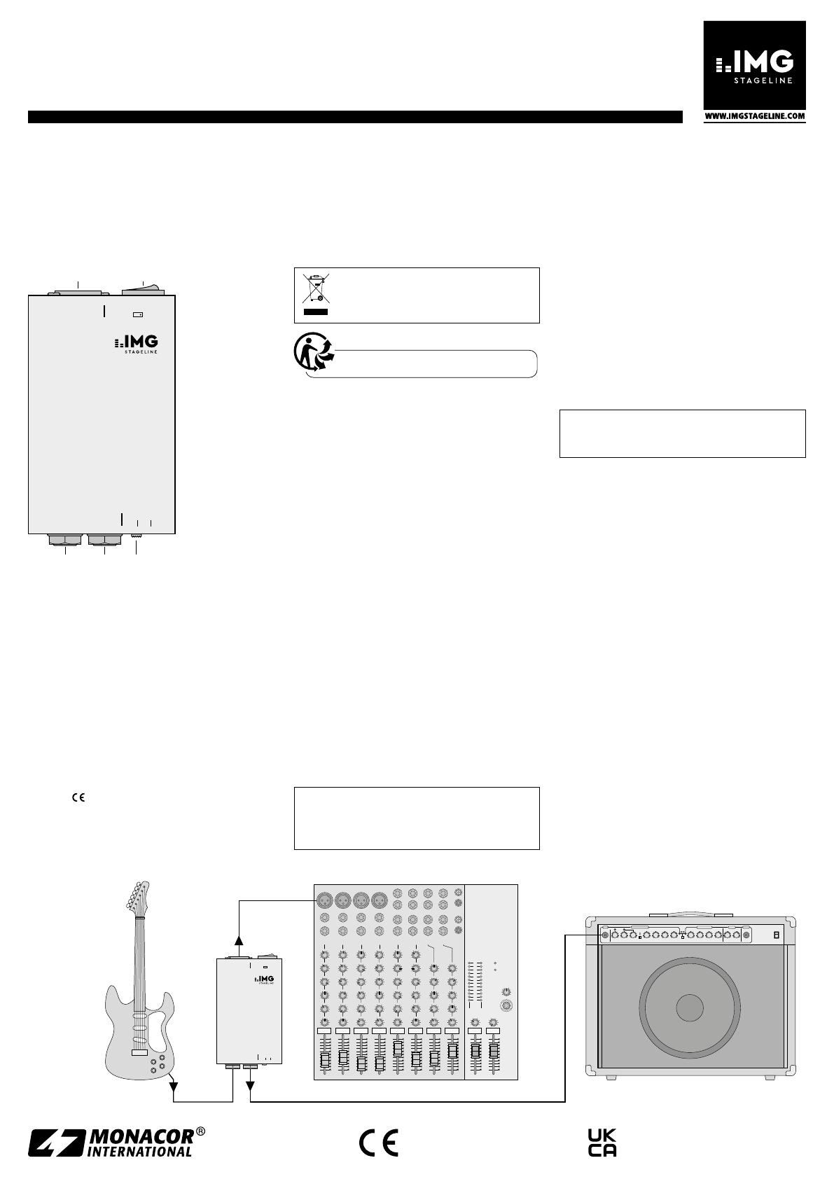
4.3 Utilisation de la sortie pour repiquage
Si le signal d’un instrument doit être distribué
simultanément à un amplificateur, reliez l’entrée
amplificateur à la prise « PAR. OUT » (4) [voir
schéma ci-dessous] ; le signal venant de l’instru-
ment y est directement appliqué.
Attention ! La sortie pour repiquage n’est
pas adaptée pour brancher des haut-parleurs.
Risque de surcharge !
4.4 Interrupteur Groundlift
Si l’interrupteur Groundlift (2) est sur la position
« OFF », la masse de l’entrée asymétrique (3) est
reliée à la masse de la sortie symétrique (1). Sé-
lectionnez tout d’abord cette position. En cas de
ronflement, mettez l’interrupteur sur la position
« ON ». La masse entre l’entrée et la sortie est
séparée (séparation galvanique).
5 Caractéristiques techniques
Bande passante : . . . . . . . 15 – 30 000 Hz, ±0 dB
Atténuation du
signal d’entrée : . . . . . . . 0 dB, 20 dB, 40 dB
Entrée
1 × jack 6,35 : . . . . . . . 50 kΩ, asymétrique
Sorties
1 × jack 6,35 : . . . . . . . sortie pour repiquage,
asymétrique
1 × XLR : . . . . . . . . . . . 600 Ω, symétrique
Rapport de transmission : 10 : 1
Température de fonc. : . . 0 – 40 °C
Dimensions : . . . . . . . . . . 74 × 45 × 130 mm
Poids : . . . . . . . . . . . . . . . 560 g
Tout droit de modification réservé.
dité élevée de l’air. La température ambiante
admissible est 0 – 40 °C.
Pour le nettoyer, utilisez un chiffon sec et doux,
en aucun cas de produits chimiques ou d’eau.
Nous déclinons toute responsabilité en cas de
dommages corporels ou matériels résultants si
le produit n’est pas correctement utilisé ou ré-
paré; en outre, la garantie deviendrait caduque.
Lorsque le produit est définitivement
retiré du service, éliminez-le conformé-
ment aux directives locales.
CARTONS ET EMBALLAGE
PAPIER À TRIER
3 Possibilités d’utilisation
Le boîtier d’injection directe DIB-100, DI-Box
(Direct Injection), permet de brancher de ma-
nière optimale un instrument de musique avec
une sortie haute impédance, asymétrique, à une
entrée basse impédance, symétrique, d’une table
de mixage (voir schéma ci-dessous). La connexion
symétrique à la table permet d’éviter des interfé-
rences en cas de longs branchements.
Les niveaux élevés de signaux peuvent être
réduits avec l’atténuateur et adaptés à l’entrée de
la table de mixage. Il est ainsi possible de connec-
ter directement le boîtier à la sortie haut-parleur
d’un amplificateur d’instrument (p. ex. amplifica-
teur de guitare). L’impact de l’amplificateur sur la
tonalité du signal reste ainsi maintenue.
4 Fonctionnement
Le boîtier d’injection directe ne nécessite aucune
alimentation.
4.1 Branchement de l’entrée asymétrique
Reliez la sortie de l’instrument de musique à la
prise d’entrée « INPUT » (3). Alternativement, la
prise d’entrée peut également être reliée à la sor-
tie haut-parleur d’un amplificateur d’instrument.
Attention ! Ne branchez jamais les sorties
haut-parleur des amplificateurs qui fonctionnent
en mode bridgé car elles sont court-circuitées
par le boîtier d’injection directe.
amplificateur d’instrumenttable de mixage
DI-Boxinstrument
de musique
DIB-100
Référence numérique 0241140
Français
© MONACOR INTERNATIONAL
All rights reserved
A-0539.99.05.04.2023
MONACOR INTERNATIONAL GmbH & Co. KG
Zum Falsch 36, 28307 Bremen
Germany
Importer: Epic Audio Ltd, Unit 9 Apollo Park
Station road, Long Buckby, NN6 7PF
United Kingdom, Company Registration: 13878247
THE AUDIO COMPANY THE AUDIO COMPANY THE AUDIO COMPANY THE AUDIO COMPANY THE AUDIO COMPANY THE AUDIO COMPANY THE AUDIO COMPANY THE AUDIO COMPANY
DI B-100
0dB –40–20
PAR. OUT
UNBAL . 50kΩ
INPUT ATT.
GROUND LIFTOUTPUT
BAL. 600Ω OFF ON
PROFESSIONAL
GUITAR AMPLIFI ER
GAIN 1
010
OVERDRIVE CHANNEL
GAIN 2
INPUT
CONTOUR
GAIN
SELECT
1
2
BASS
010
MIDDLE
010
TREBLE
010
LEVEL
010
LEVEL
010
BASS
010
MIDDLE
010
TREBLE
010
REVERB
010
VOLUME
010
MIN. 8 Ω
PHONES
NORMAL CHANNEL
CHANNEL
SELECT
MASTER
POWER
010 010
12-INPUT MIXING CONSOLE
AUX RTN1 AUX RTN2 AUX SEND MAIN OUT
TAPE IN
CH 1CH2 CH 3CH4 CH 5/6 CH 7/8 CH9/10 CH11/12
5/6 7/8 9/10 11/12
LINE LINE LINE LINE
HIGH
AUX1
AUX RTN1 AUX RTN2
LEVEL
HIGH
AUX1
HIGH
AUX1
HIGH
AUX1
HIGH
AUX1
HIGH
AUX1
HIGH
AUX1
HIGH
AUX1
PHANTOM POWER
POWER
PHONES
LEFT RIGHT
LR
C
010
5
-15 +15
0
-15 +15
0
010
5
010
5
GAIN
LOW
AUX2
PAN
10
0
5
+20
U
10
0
5
+20
U
10
0
5
+20
U
10
0
5
+20
U
10
0
5
+20
U
10
0
5
+20
U
10
0
5
+20
U
10
0
5
+20
U
10
0
5
+10
U
10
0
5
+10
U
010
5
010
5
010
5
LR
C
010
5
-15 +15
0
-15 +15
0
010
5
010
5
GAIN
LOW
AUX2
PAN
LR
C
010
5
-15 +15
0
-15 +15
0
010
5
010
5
GAIN
LOW
AUX2
PAN
LR
C
010
5
-15 +15
0
-15 +15
0
010
5
010
5
GAIN
LOW
AUX2
PAN
LR
C
010
5
-15 +15
0
-15 +15
0
010
5
010
5
GAIN
LOW
AUX2
BAL
LR
C
010
5
-15 +15
0
-15 +15
0
010
5
010
5
GAIN
LOW
AUX2
BAL
LR
C
010
5
-15 +15
0
-15 +15
0
010
5
LOW
AUX2
BAL
LR
C
010
5
-15 +15
0
-15 +15
0
010
5
LOW
AUX2
BAL
TAPE OUT
L
R
L
R
1
2
L
R
L
R
L
R
L
R
L
R
L
R
L
R
MIC MIC MIC MIC
LINE
INSER T
LINE
INSER T
LINE
INSER T
LINE
INSER T
+22
+10
+7
+4
+2
0
–2
–4
–7
–10
–20
–30
CLIP
LR1234
amplificatore per strumenti musicalemixer
DI-boxstrumento
musicale
DI-box
Queste istruzioni sono rivolte a utenti con
conoscenze base nella tecnica audio. Vi
preghiamo di leggerle attentamente prima
della messa in funzione e di conservarle per
un uso futuro.
1 Panoramica
2
3 4 5
1
DIB-100
PAR. OUT
UNBAL. 50 kΩ
INPUT
OUTPUT
BAL. 600Ω
GROUND LIFT
OFF ON
0 dB – 40–20
ATT.
1 Uscita simmetricha (XLR)
2 Interruttore Groundlift per separare la massa
fra l’ingresso (3) e l’uscita (1)
3 Ingresso asimmetrico ( jack 6,3 mm)
4 Uscita di attraversamento asimmetrica ( jack
6,3 mm): possibilità di prelevare il segnale d’in-
gresso della presa (3)
5 Cursore “ATT.” per attenuare il segnale d’in-
gresso
2 Avvertenze importanti
Il prodotto è conforme a tutte le direttive rilevanti
dell’UE e pertanto porta la sigla .
Il prodotto è adatto solo per uso interno. Pro-
teggerlo da gocce e spruzzi d’acqua e da un’e-
levata umidità dell’aria. L’intervallo di tempera-
tura ambiente ammissibile è 0 40 °C.
presenta delle distorsioni, posizionare il cursore su
“−20” oppure, con segnali molto alti, su “−40”.
4.2 Collegare l’uscita simmetrica
Il segnale simmetrico d’uscita è disponibile alla
uscita XLR (1). Collegare l’uscita con l’ingresso ad
alta sensibilità di un mixer (p. es. l’ingresso per
un microfono), servendosi di un cavo simmetrico.
4.3 Sfruttare l’uscita di attraversamento
Se il segnale dello strumento deve arrivare diret-
tamente ad un amplificatore, collegare l’ingresso
dell’amplificatore con la presa “PAR. OUT” (4)
[vedi illustrazione in basso], dove è presente il
segnale proveniente dallo strumento musicale.
Attenzione! L’uscita di attraversamento non è
adatta per il collegamento di altoparlanti. Peri-
colo di sovraccarico!
4.4 Interruttore groundlift
Se l’interruttore groundlift (2) è in posizione
“OFF”, la massa dell’ingresso asimmetrico (3) è
collegata con la massa dell’uscita simmetrica (1).
Questa è la configurazione normale. Se si pre-
sentano invece degli ronzii, portare l’interruttore
su “ON”. La massa fra l’ingresso e l’uscita viene
separata (separazione galvanica).
5 Dati tecnici
Banda passante: . . . . . . . 15 – 30 000 Hz, ±0 dB
Attenuazione del
segnale d’ingresso: . . . . . 0 dB, 20 dB, 40 dB
Ingresso
1 × jack 6,3 mm: . . . . . . 50 kΩ, asimm.
Uscite
1 × jack 6,3 mm: . . . . . . uscita di attraversa-
mento, asimm.
1 × XLR: . . . . . . . . . . . . 600 Ω, simm.
Rapporto di trasmissione: . 10 : 1
Temperatura ambiente: . . 0 – 40 °C
Dimensioni: . . . . . . . . . . . 74 × 45 × 130 mm
Peso: . . . . . . . . . . . . . . . . 560 g
Con riserva di modifiche tecniche.
Per la pulizia usare solo un panno morbido e
asciutto; non impiegare in nessun caso prodotti
chimici o acqua.
Non si accettano richieste di garanzia per il
prodotto e nessuna responsabilità per eventuali
danni alle persone o alle cose che ne derivano,
se il prodotto non viene usato correttamente o
non viene riparato a regola d’arte.
Se il prodotto deve essere messo defini-
tivamente fuori uso, smaltire il prodotto
in conformità alle norme locali.
3 Possibilità d’impiego
La DI-box (direct injection) DIB-100 serve per
collegare in modo ottimale un strumento musi-
cale con uscita asimmetrica, ad alta impedenza,
con gli ingressi simmetrici, a bassa impedenza di
un mixer (vedi illustrazione in basso). Grazie al
collegamento simmetrico con il mixer si possono
escludere, anche nel caso di cavi lunghi, le radia-
zioni di disturbo.
Gli alti livelli del segnale possono essere smor-
zati con il attenuatore e adattati all’ingresso del
mixer. Così è possibile collegare una DI-box diret-
tamente all’uscita per altoparlanti di un amplifica-
tore per strumento musicale (p. es. per chitarre).
La regolazione del suono tramite l’amplificatore
rimane pertanto valida.
4 Messa in funzione
La DI-box non richiede nessuna alimentazione di
corrente.
4.1 Collegare l’ingresso asimmetrico
Collegare l’uscita dello strumento musicale con
la presa d’ingresso “INPUT” (3). In alternativa, la
presa d’ingresso può essere collegata anche con
l’uscita per altoparlanti di un amplificatore per
strumenti musicali.
Attenzione! Non collegare le uscite per al-
toparlanti di amplificatori con circuito a ponte
perché si avrebbe un cortocircuito per mezzo
della DI-box.
Se il cursore “ATT.” (5) si trova completamente a
sinistra in posizione “0 dB”, il livello del segnale
d’ingresso non viene attenuato. Se il mixer a valle
DIB-100
Codice 0241140
Italiano
  • Page 1 1
  • Page 2 2
  • Page 3 3
  • Page 4 4

IMG STAGELINE DIB-100 Manuale utente

Tipo
Manuale utente