ProLights SOLAR27Q Manuale utente
- Categoria
- Stroboscopi
- Tipo
- Manuale utente

USER MANUAL
MANUALE UTENTE
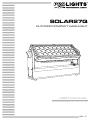
SOLAR27Q
OUTDOOR COMPACT WASHLIGHT
EN - IT

All rights reserved by Music & Lights S.r.l. No part of this instruction manual may be
reproduced in any form or by any means for any commercial use.
In order to improve the quality of products, Music&Lights S.r.l. reserves the right to modify the characteris-
tics stated in this instruction manual at any time and without prior notice.
All revisions and updates are available in the ‘manuals’ section on site www.musiclights.it
REV.002-12/18

1
SOLAR27Q
Packing content
• SOLAR27Q
• S27QFILTER60
• Power cable
• User manual
TABLE OF CONTENTS
Safety
General instructions
Warnings and installation precautions
1 Introduction
1. 1 Description
1. 2 Technical specications
1. 3 Operating elements and connections
2 Installation
2. 1 Mounting
3 Functions and settings
3. 1 Operation
3. 2 Basic
3. 3 Menu structure
3. 4 Linking
3. 5 DMX addressing conguration
3. 6 DMX mode conguration
3. 7 DMX addressing
3. 8 Wireless
3. 9 Screen
3. 10 Dimmer mode
3. 11 White balance
3. 12 LED Frequency
3. 13 Factory reload
3. 14 Information
3. 15 Master/Slave
3. 16 Eect
3. 17 Static
3. 18 Manual
3. 19 Connection of the DMX line
3. 20 Construction of the DMX termination
3. 21 DMX control
4 Maintenance
4. 1 Maintenance and cleaning the unit
4. 2 Trouble shooting
2
2
3
3
5
6
7
7
8
9
9
9
9
10
10
11
11
11
11
11
12
12
12
12
13
13
14
17
17

SOLAR27Q
2
WARNING! Before carrying out any operations with the unit, carefully read this instruction
manual and keep it with cure for future reference. It contains important information about
the installation, usage and maintenance of the unit.
SAFETY
General instruction
• The products referred to in this manual conform to the European Community Directives and are there-
fore marked with .
• The unit is supplied with hazardous network voltage (230V~). Leave servicing to skilled personnel only.
Never make any modications on the unit not described in this instruction manual, otherwise you will
risk an electric shock.
• Connection must be made to a power supply system tted with ecient earthing (Class I appliance ac-
cording to standard EN 60598-1). It is, moreover, recommended to protect the supply lines of the units
from indirect contact and/or shorting to earth by using appropriately sized residual current devices.
• The connection to the main network of electric distribution must be carried out by a qualied electrical
installer. Check that the main frequency and voltage correspond to those for which the unit is designed
as given on the electrical data label.
• This unit is not for home use, only professional applications.
• Never use the xture under the following conditions:
- in places subject to vibrations or bumps;
- in places with an ambient temperature of over 50°C.
• Make certain that no inammable liquids, water or metal objects enter the xture.
• Do not dismantle or modify the xture.
• All work must always be carried out by qualied technical personnel. Contact the nearest sales point for
an inspection or contact the manufacturer directly.
• If the unit is to be put out of operation denitively, take it to a local recycling
plant for a disposal which is not harmful to the environment.
Warnings and installation precautions
• If this device will be operated in any way dierent to the one described in this manual, it may suer
damage and the guarantee becomes void. Furthermore, any other operation may lead to dangers like
short circuit, burns, electric shock, etc.
• Before starting any maintenance work or cleaning the projector, cut o power from the main supply.
• Always additionally secure the projector with the safety rope. When carrying out any work, always com-
ply scrupulously with all the regulations (particularly regarding safety) currently in force in the country
in which the xture’s being used.
• The minimum distance between the xture and surrounding walls must be more than 50 cm and the
air vents at the housing must not be covered in any case.
• Install the xture in a well ventilated place.
• Keep any inammable material at a safe distance from the xture.
• The maximum temperature that can be reached on the external surface of the tting, in a thermally
steady state, is high. After power o, please cool down over 15 minutes.
• Shields, lenses or ultraviolet screens shall be changed if they have become damaged to such an extent
that their eectiveness is impaired.
• The lamp (LED) shall be changed if it has become damaged or thermally deformed.
• Never look directly at the light beam. Please note that fast changes in lighting, e. g. ashing light, may
trigger epileptic seizures in photosensitive persons or persons with epilepsy.

3
SOLAR27Q
- 1 - INTRODUCTION
1.1 DESCRIPTION
SOLAR27Q is a compact fan-free outdoor wash light featuring an outstanding brightness of 10,832
lumens. Equipped with 27x10W RGBW full colour LEDs, delivering superior colour mixing. Featuring a
slim size as well as the multiple interchangeable optics through magnets, including asymmetrical lters
which, all together, make the SOLAR27Q an incredibly exible device for indoor use and outdoor. Whilst
highly-powerful, the SOLAR27Q also benets from being silent.
1.2 TECHNICAL SPECIFICATIONS
LIGHT SOURCE
• Source:27x10 W CREE RGBW
• CT:5960 K
• CRI:71,8
• Luminous Flux:@FULL 10832 lm - With included lter 6987 lm
• Lux:@FULL (25°) 6133 lux - With included lter 1027 lux @3m Full
• Lux:@FULL (25°) 2208 lux - With included lter 370 lux @5m Full
• Source Life Expectancy: >50.000 h
• Other:Magnetic lter included to achieve 45° (60° lter), barndoor not included
OPTICS
• Beam angle:25° - With included lter 45 °
• Field angle:39° - With included lter 69 °
• Lens diameter:36 mm
• Lens type: honeycomb gapless plano-convex optics
• Additional optics:10° / 15° / 45° / 40° lter / 10X60° lter / 30X60° lter
COLOR SYSTEM
• Color Mixing: RGBW/FC
• CTC: CTC control through independent DMX channel
• Color Wheel: Virtual color wheel with presets
DYNAMIC EFFECTS
• Static Color Mode: Selection of static color
• Manual Color Mode: Manual adjustment of color
• Auto Mode: Built-in programs with execution speed adjustment
BODY
• Hardware On-board:Magnetic lter frame with 45° lter
• Tilt Angle:+/- 90 ° Manual
• Body: Sturdy die-cast aluminium body conceived for long-time durability
• Body Color: Black
CONTROL
• Protocols: DMX512, RDM, W-DMX
• DMX channels:5 / 7 / 10 / 13 / 17 channel
• Pixel control:3 horizontal individually select and control sections
• W-DMX: included, wireless solution receiver
• RDM: RDM ready for xture remote monitor and settings

SOLAR27Q
4
• Display: black OLED high resolution display
• Firmware upgrade: yes, via USB-DMX interface (UPBOX1) not included
• Master/Slave: for synchronized operation of more units linked in a chain
ELECTRONICS
• Dimmer: linear 0~100% electronic dimmer
• Dimmer curves: dierent dimming curves available
• Battery backup: battery backup for user operation without connecting to the main power
• Operating temperature: -20° ~ +50°
• Flicker: icker free frequency with adjustable PWM
• Selectable PWM: 600~25K Hz
ELECTRICAL
• Power supply: 100-240V – 50/60Hz
• Power consumption (at 230V):268 W
• Power consumption (at 120V):275 W
• Output (at 230V):9 units on a single power line
• Output (at 120V):5 units on a single power line
• Power factor:0,994
PHYSICAL
• Cooling: natural cooling of the peculiar chassis and to absence of fans
• Sospension and xing: hanging bracket for oor positioning with “Quick-Lock” system
• Signal connection: Seetronic XLR 5p IN/OUT connectors
• Data connection: W-DMX OEM TRX
• Power connection: Seetronic powerCON waterproof IN/OUT connectors
• IP rating:65 for temporary outdoor application, not for xed installation
• Dimensions (WxHxD):454x153x268.5 mm
• Weight:9 kg
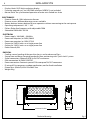
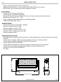
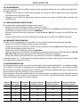
Technical drawing
Fig.1
454mm/17,87in
83mm/
3,26in
268.5mm/11,24in

5
SOLAR27Q
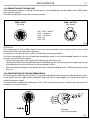
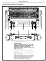
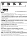
1 32
8
9 9 8
4 5 6 7 1
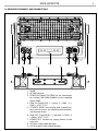
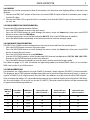
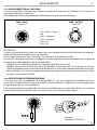
1.3 OPERATING ELEMENTS AND CONNECTIONS
1. KNOB
2. W-DMX receiver
3. POWER IN (PowerCON TRUE IN): for connection
to a socket (100-240V/50-60Hz) via the supplied
mains cable,
4. DMX IN (5-pole XLR): 1 = massa, 2 = DMX -, 3 =
DMX +, 4 N/C, 5 N/C.
5. CONTROL PANEL with display and 4 touch but-
tons used to access the control panel functions
and manage them.
6. DMX OUT (5-pole XLR): 1 = ground, 2 = DMX-, 3
= DMX+, 4 N/C, 5 N/C.
7. POWER OUT: connect to supply power to the
next unit.
8. HOLE for safety cable passage
9. HOLE for quick-lock omega bracket
Fig.2

SOLAR27Q
6
- 2 - INSTALLATION
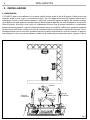
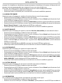
2.1 MOUNTING
The SOLAR27Q may be set up on a solid and even surface. By means of the xing facilities of the baseplate,
the unit can also be mounted upside down to a cross arm. The base plate is shown in g.3. For xing, stable
mounting clips are required. According to the gure, the bolts of the brackets are placed into the openings
provided in the base plate and turned clockwise until they lock (to the stop). Always ensure that the unit
is rmly xed to avoid vibration and slipping while operating. The mounting place must be of sucient
stability and be able to support a weight of 10 times of the unit’s weight. When carrying out any installa-
tion, always comply scrupulously with all the regulations (particularly regarding safety) currently in force
in the country in which the xture’s being used. Always additionally secure the projector with the safety
rope from falling down. For this purpose, fasten the safety rope at a suitable position so that the maximum
fall of the projector will be 20 cm.
Fig.3
OMEGA
QUICK-LOCK
SAFETY
CABLE
SAFETY
CABLE
CLAMP

7
SOLAR27Q
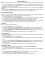
- 3 - FUNCTIONS AND SETTINGS
3.1 OPERATION
Connect the supplied main cable to a socket (100-240V~/50-60Hz). The unit will run built-in program to
reset all motors to their home position. Shortly after that the SOLAR27Q is ready for operation. To switch
o, disconnect the mains plug from the socket. For a more convenient operation it is recommended to
connect the unit to a socket which can be switched on and o via light switch.
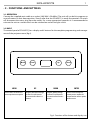
3.2 BASIC
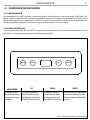
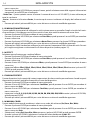
The control panel of SOLAR27Q has a display and 4 buttons for the complete programming and manage-
ment of the projector menu (g.4).
MENU UP DOWN ENTER
Used to access the menu or to
return a previous menu option
Navigates downwards through
the menu list and increases
the numeric value when in a
function
Navigates upwards through
the menu list and decreases
the numeric value when in a
function
Used to select and store the
current menu or conrm the
current function value or option
within a menu
Fig.4 - Functions of the buttons and display icons
Up
Down
Mode
Enter

SOLAR27Q
8
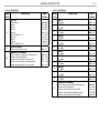
3.3 MENU STRUCTURE
MENU
1 CONNECT
ð
DMX Address
ð
1-512
DMX Mode
ð
5CH
7CH
10CH
13CH
17CH
Wireless
ð
Receive On/O
Receive Reset
ð
ð
On/O
No/Yes
Wireless on DMX
ð
No/Yes
2 SET UP
ð
Screen
ð
Backlight
Key Lock
ð
ð
On/10s/20s/30s
No/Yes
3 ADVANCED
ð
Dimmer Mode
ð
O/Dimmer1/2/3
White Balance
ð
O
Adjust
ð
Red
Green
Blue
White
ð
<125-255>
LED Frequency
ð
600Hz/1200Hz/2000Hz/4000Hz/6000Hz/25kHz
Factory Reload
ð
No/Yes
4 INFORMATION
ð
Fixture Time
Version
UID
ð
ð
ð
0-9999
V1.0
<15D00220****>
5 STAND ALONE
ð
Master/Slave
ð
Master
Slave
Eects
ð
Eect1
…
Eect9
ð
Speed 1-100
Static
ð
Fixed Color
ð
R
G
B
W
GB
RB
RG
RGB
RW
GW
BW
RGW
RBW
GBW
RGBW
ð
Manual color
ð
Red
Green
Blue
White
ð
<000-255>

9
SOLAR27Q
3.4 LINKING
Multiple units can be connected so that all secondary units have the same lighting eect as the main unit
(Master).
1. Connect the DMX OUT output of the main unit to the DMX IN input of the rst secondary unit using a
5 pole XLR cable.
2. Connect the DMX OUT output of the rst secondary unit with the DMX IN input of the second second-
ary unit, etc.
3.5 DMX ADDRESSING CONFIGURATION
To enter the DMX mode proceed as follows:
• Press the ENTER button to access the main menu.
• Press the UP/DOWN button to scroll through the menu, select the Connect icon, then press the ENTER
button to access the next DMX Address.
• Use the arrow buttons to set the desired value (001-512). Press the ENTER button to conrm.
• Press the MENU button repeatedly to exit the menu and to save the changes made.
3.6 DMX MODE CONFIGURATION
SOLAR27Q has 5 DMX channel congurations that can be accessed from the control panel.
• Press the ENTER button to access the main menu.
• Press the UP/DOWN button to scroll through the menu, select the Connect icon, then press the ENTER
button to enter the next menu.
• Press the UP/DOWN button to select DMX Mode.
• Use the UP/DOWN button to select the desired DMX channel conguration (5CH, 7CH, 10CH, 13CH, 17CH),
then press the ENTER button to conrm the selection.
• Press the MENU button repeatedly to exit the menu and to save the changes made.
The tables on page 14, 15 and 16 indicate the operating modes and related DMX values. As an interface
DMX, the unit has 5-pin XLR contacts.
3.7 DMX ADDRESSING
For operation via a light control unit with DMX512 protocol, simply connect SOLAR27Q to the controller.
The projector has a DMX channel conguration that can be accessed from the control panel. In order to
control SOLAR27Q with a light control unit, the DMX start address must be set for the rst DMX channel.
If, for example, the address 33 is provided on the control unit to control the function of the rst DMX chan-
nel, the start address 33 must be set on the SOLAR27Q. The other panel functions will be automatically
assigned to the following addresses.
Number of
DMX chan-
nels
Start address
(example)
DMX Address
occupied
Next possible start
address for unit No. 1
Next possible start
address for unit No. 2
Next possible start
address for unit No. 3
5 33 33-37 38 43 48
7 33 33-39 40 47 54
10 33 33-42 43 53 63
13 33 33-45 46 59 72
17 33 33-49 50 67 84

SOLAR27Q
10
3.8 WIRELESS
To change the wireless control settings, proceed as follows:
• Press the ENTER button to access the main menu.
• Press the UP/DOWN button to scroll through the menu, select the Connect icon, then press the ENTER
button to enter the next menu.
• Press the UP/DOWN button to select Wireless and press the ENTER button to proceed.
• Select the proposed option with the UP/DOWN button and press the ENTER button to conrm your
choice.
3. Receive On/O - Disables/enables the DMX signal via cable. Select OFF to deactivate the function or ON
to activate the function.
4. Receive Reset - Reset the unit’s wireless connection. Select NO to deactivate the function or YES to acti-
vate the function.
5. Wireless on DMX - able or disable this function if you need or not to retransmitt on DMX out of the unit the
same DMX signal received from wireless transmitter.
• Press the ENTER button to conrm the selection.
• Press the MENU button repeatedly to exit the menu and to save the changes made.
NOTE: If the projector is in Blackout mode before synchronizing with the transmitting wireless unit, and
if the wireless signal is lost after synchronization with the transmitting unit, the projector will remain on
according to the last received DMX value.
If the projector was in STATIC or AUTO mode before synchronizing with the wireless transmitter, if the
wireless signal is lost after synchronization with the transmitting unit, the projector will return to the previ-
ously set STATIC or AUTO.
3.9 SCREEN
It is possible to modify the following parameters, related to the display, following the same procedure:
• Press the ENTER button to access the main menu.
• Press the UP/DOWN button to scroll through the menu, select Set Up, then press the ENTER button to
access the next menu.
• Press the UP/DOWN button to select Screen and press the ENTER button to proceed.
• Select the proposed option with the UP/DOWN button and press the ENTER button to conrm.
- Backlight - Auto O display backlight. This function allows you to switch o automatically the backlighting
of the display after a certain time which can be set using the directional keys. To have the display always
on select On or set a value (10s /20s/30s) to turn o the display once the chosen time has elapsed, after exit-
ing the menu.
- Key lock - With this function, you can lock the keys on the control panel to prevent, for example, tampering
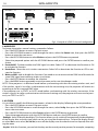
Fig.5 - Example of a DMX 5-channel conguration
DMX Address: 53DMX Address: 43DMX Address: 38 DMX Address: 48
. . . . . . . . . . . .
DMX512 Controller

11
SOLAR27Q
with the settings. If this function is activated, the keys are locked automatically. To disable or temporarily
disable or disable the key lock function, press the keys in the following order to regain access to the menu
commands:
UP, DOWN, UP, DOWN, ENTER. Select YES to activate the function or NO to deactivate it.
• Press the ENTER button to conrm the selection.
• Press the MENU key repeatedly to exit the menu and to save the changes made.
3.10 DIMMER MODE
Select this function to choose to simulate dierent dimming curves.
• Press the ENTER button to access the main menu.
• Press the UP/DOWN button to scroll through the menu, select the Advanced icon, then press the ENTER
button to enter the next menu.
• Press the UP/DOWN button to select Dimmer Mode and press the ENTER button to proceed.
• Press the UP/DOWN button to scroll through the menu, then select O to deactivate or select Dimmer1/
Dimmer2 /Dimmer3. Then select ENTER to conrm.
• Press the MENU button repeatedly to exit the menu and to save the changes made.
3.11 WHITE BALANCE
Select this function to adjust e Red, Green, Blue and White parameter to make dierent whites.
• Press the ENTER button to access the main menu.
• Press the UP/DOWN button to scroll through the menu, select the Advanced icon, then press the ENTER
button to enter the next menu.
• Press the UP/DOWN button to select White Balance and press the ENTER button to proceed.
• Press the UP/DOWN button to scroll through the menu, then select O to deactivate the balance. Select
Adjust to balance with following colors: Red, Green, Blue, White. Then select ENTER to conrm.
• Set the desired value (125-255)and press the ENTER button to conrm..
• Press the MENU button repeatedly to exit the menu and to save the changes made.
3.12 LED FREQUENCY
Select this function to adjust the frequency of LED.
• Press the ENTER button to access the main menu.
• Press the UP/DOWN button to scroll through the menu, select the Advanced icon, then press the ENTER
button to enter the next menu.
• Press the UP/DOWN button to select LED Frequency and press the ENTER button to proceed.
• Press the UP/DOWN button to select one of available setting: 600Hz, 1200Hz, 2000Hz, 4000Hz, 6000Hz25kH.
Then select ENTER to conrm.
• Press the MENU button repeatedly to exit the menu and to save the changes made.
3.13 FACTORY RELOAD
Select this function to reset the unit to the factory settings.
• Press the ENTER button to access the main menu.
• Press the UP/DOWN button to scroll through the menu, select the Advanced icon, then press the ENTER
button to access the next menu.
• Press the UP/DOWN button to select Factory Reload and press the ENTER button to proceed.
• Press the UP/DOWN buttons to select ON or OFF, then press the ENTER button to conrm.
• Press the MENU button repeatedly to exit the menu and to save the changes made.
3.14 INFORMATION
To view all the information on the device, proceed as follows:
• Press the ENTER button to access the main menu.

SOLAR27Q
12
• Press the UP/DOWN button to select Information, then press the ENTER button to enter the next menu.
• Press the UP/DOWN button to scroll through the menu, then select one of the following information
and press the ENTER button to display it.
- Fixture Time - This option shows the user the amount of hours the SOLAR27Q has been in use throughout
its lifetime.
- Version - Through the Version function, the version can be viewed on the display of the installed software.
• Press the MENU button repeatedly to exit the menu and to save the changes made.
3.15 MASTER/SLAVE MODE
This mode will allow you to link up the units together without a controller. Choose a unit to function as the
Master. The unit must be the rst unit in line; other units will work as slave.
• Press the ENTER button to access the main menu.
• Press the UP/DOWN button to select Stand Alone, then press the ENTER button to enter the next menu.
• Press the UP/DOWN button to select Master/Slave and press the ENTER button to proceed.
• Press the MENU button repeatedly to exit the menu and to save the changes made.
• Use standard DMX cables to daisy chain your units together via the DMX connector on the rear of the
units. For longer cable runs we suggest a terminator at the last xture (see page 13).
3.16 EFFECT
Select this function to choose the eect.
• Press the ENTER button to access the main menu.
• Press the UP/DOWN button to select Stand Alone, then press the ENTER button to enter the next menu.
• Press the UP/DOWN button to select Eects, then press the ENTER button to enter the next menu.
• Set the eect Eect1, Eect2, Eect3, Eect4, Eect5, Eect6, Eect7, Eect8, Eect9 through the UP/DOWN but-
tons, then press ENTER.
• Press the MENU button repeatedly to exit the menu and to save the changes made.
3.17 STATIC MODE
This xture has the ability to accept custom static color settings. Access these chases via the control panel
on the back of the xture.
• Press the ENTER button to access the main menu.
• Press the UP/DOWN button to select Stand Alone, then press the ENTER button to enter the Static next
menu.
• Press the UP/DOWN button to select Fixed Color, then press the ENTER button to enter the next menu.
• Set the colors R, G, B, W, GB, RB, RG, RGB, RW, GW, BW, RGW, RBW, GBW, RGBW through the UP/DOWN buttons,
then press ENTER.
• Press the MENU button repeatedly to exit the menu and to save the changes made.
3.18 MANUAL COLOR
This mode allows to combine the colors red, green, blue and white (Red, Green, Blue, White).
• Press the ENTER button to access the main menu.
• Press the UP/DOWN button to select Stand Alone, then press the ENTER button to enter the Static next
menu.
• Select the color Red, Green, Blue, White through the UP/DOWN buttons, then press ENTER.
• Using UP/DOWN buttons, select the desired color value 000 - 255.
• Press the MENU button repeatedly to exit the menu and to save the changes made.

13
SOLAR27Q
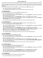
3.19 CONNECTION OF THE DMX LINE
DMX connection employs standard XLR connectors. Use shielded pair-twisted cables with 120Ω imped-
ance and low capacity.
The following diagram shows the connection mode:
Fig.6
DMX - OUTPUT
XLR socket
DMX - INPUT
XLR plug
Pin1 : GND - Shield
Pin2 : - Negative
Pin3 : + Positive
Pin4 : N/C
Pin5 : N/C
ATTENTION
The screened parts of the cable (sleeve) must never be connected to the system’s earth, as this would
cause faulty xture and controller operation.
Over long runs can be necessary to insert a DMX level matching amplier.
For those connections the use of balanced microphone cable is not recommended because it cannot
transmit control DMX data reliably.
• Connect the controller DMX input to the DMX output of the rst unit.
• Connect the DMX output to the DMX input of the following unit. Connect again the output to the input
of the following unit until all the units are connected in chain.
• When the signal cable has to run longer distance is recommended to insert a DMX termination on the
last unit.
3.20 CONSTRUCTION OF THE DMX TERMINATION
The termination avoids the risk of DMX 512 signals being reected back along the cable when they reach-
es the end of the line: under certain conditions and with certain cable lengths, this could cause them to
cancel the original signals.
The termination is prepared by soldering a 120Ω 1/4 W resistor between pins 2 and 3 of the 5-pin male XLR
connector, as shown in gure.
Fig.7
Example:
5 pin XLR connector

SOLAR27Q
14
3.21 DMX CONTROL
5 CHANNEL
MODE
FUNCTION DMX
Value
5 Ch
1
RED
0~100% 000 - 255
2
GREEN
0~100% 000 - 255
3
BLUE
0~100% 000 - 255
4
WHITE
0~100% 000 - 255
5
DIMMER SPEED MODE
Preset dimmer speed from display menu
Dimmer speed mode o
Dimmer speed mode1 (fast speed)
Dimmer speed mode2 (middle speed)
Dimmer speed mode3 (slow speed)
000-051
052-101
102-152
153-203
204-255
10 CHANNEL
MODE
FUNCTION DMX
Value
10 Ch
1
DIMMER
0~100% 000 - 255
2
RED
0~100% 000 - 255
3
GREEN
0~100% 000 - 255
4
BLUE
0~100% 000 - 255
5
WHITE
0~100% 000 - 255
6
STROBE
No function
Strobe Slow to Fast
000 - 010
011 - 255
7
COLOR MACRO
No Function
R 100%, G 0~100%, B 0 %
R 100%~0 %, G 100%, B 0 %
R 0 %, G 100%, B 0~100%
R 0 %, G 100~0 %, B 100%
R 0~100%, G 0 %, B 100%
R 100%, G 0 %, B 100~0 %
R 100%, G 0~100%, B 0~100%
R 100~0 %, G 100~0 %, B 100%
R 100%, G 100%, B 100%, W 100%
2800k
3000k
3200k
4000k
5600k
6000k
6500k
7000k
8000k
9000k
10000k
000 - 010
011 - 030
031 - 050
051 - 070
071 - 090
091 - 110
111 - 130
131 - 150
151 - 170
171 - 200
201 - 205
206 - 210
211 - 215
216 - 220
221 - 225
226 - 230
231 - 235
236 - 240
241 - 245
246 - 250
251 - 255
7 CHANNEL
MODE
FUNCTION DMX
Value
7 Ch
1
DIMMER
0~100% 000 - 255
2
RED
0~100% 000 - 255
3
GREEN
0~100% 000 - 255
4
BLUE
0~100% 000 - 255
5
WHITE
0~100% 000 - 255
6
STROBE
No function
Strobe Slow to Fast
000 - 010
011 - 255
7
DIMMER SPEED MODE
Preset dimmer speed from display menu
Dimmer speed mode o
Dimmer speed mode1 (fast speed)
Dimmer speed mode2 (middle speed)
Dimmer speed mode3 (slow speed)
000-051
052-101
102-152
153-203
204-255

15
SOLAR27Q
13 CHANNEL
MODE
FUNCTION DMX
Value
13 Ch
1
RED 1
0~100% 000 - 255
2
GREEN 1
0~100% 000 - 255
3
BLUE 1
0~100% 000 - 255
4
WHITE 1
0~100% 000 - 255
5
RED 2
0~100% 000 - 255
6
GREEN 2
0~100% 000 - 255
7
BLUE 2
0~100% 000 - 255
8
WHITE 2
0~100% 000 - 255
9
RED 3
0~100% 000 - 255
10
GREEN 3
0~100% 000 - 255
11
BLUE 3
0~100% 000 - 255
12
WHITE 3
0~100% 000 - 255
13
DIMMER SPEED MODE
Preset dimmer speed from display menu
Dimmer speed mode o
Dimmer speed mode1 (fast speed)
Dimmer speed mode2 (middle speed)
Dimmer speed mode3 (slow speed)
000-051
052-101
102-152
153-203
204-255
10 CHANNEL
MODE
FUNCTION DMX
Value
10 Ch
8
EFFECTS
NO Function
Eect 1
Eect 2
Eect 3
Eect4
Eect5 (Eects1- 4)
Eect 6
Eect 7
Eect 8
Eect 9 (Eects6- 8)
000-010
011-037
038-064
065-091
092-118
119-145
146-172
173-199
200-226
227-255
9
EFFECTS SPEED
Eects speed slow to fast 000 - 255
10
DIMMER SPEED MODE
Preset dimmer speed from display menu
Dimmer speed mode o
Dimmer speed mode 1 (fast speed)
Dimmer speed mode 2 (middle speed)
Dimmer speed mode 3 (slow speed)
000 - 051
052 - 101
102 - 152
153 - 203
204 - 255

SOLAR27Q
16
17 CHANNEL
MODE
FUNCTION DMX
Value
17 Ch
1
DIMMER
0~100% 000 - 255
2
STROBE 1
No function
Strobe Slow to Fast
000 - 010
011 - 255
3
STROBE 2
No function
Strobe Slow to Fast
000 - 010
011 - 255
4
STROBE 3
No function
Strobe Slow to Fast
000 - 010
011 - 255
5
RED 1
0~100% 000 - 255
6
GREEN 1
0~100% 000 - 255
7
BLUE 1
0~100% 000 - 255
8
WHITE 1
0~100% 000 - 255
9
RED 2
0~100% 000 - 255
10
GREEN 2
0~100% 000 - 255
11
BLUE 2
0~100% 000 - 255
12
WHITE 2
0~100% 000 - 255
13
RED 3
0~100% 000 - 255
14
GREEN 3
0~100% 000 - 255
15
BLUE 3
0~100% 000 - 255
16
WHITE 3
0~100% 000 - 255
17
DIMMER SPEED MODE
Preset dimmer speed from display menu
Dimmer speed mode o
Dimmer speed mode1 (fast speed)
Dimmer speed mode2 (middle speed)
Dimmer speed mode3 (slow speed)
000 - 051
052 - 101
102 - 152
153 - 203
204 - 255

17
SOLAR27Q
- 4 - MAINTENANCE
4.1 MAINTENANCE AND CLEANING THE UNIT
• Make sure the area below the installation place is free from unwanted persons during setup.
• Switch o the unit, unplug the main cable and wait until the unit has cooled down.
• All screws used for installing the device and any of its parts should be tightly fastened and should not
be corroded.
• Housings, xations and installation spots (ceiling, trusses, suspensions) should be totally free from any
deformation.
• When the lens is visibly damaged due to cracks or deep scratches, it must be replaced.
• The main cables must be in impeccable condition and should be replaced immediately even when a
small problem is detected.
• In order to protect the device from overheating the cooling fans (if any), and ventilation openings
should be cleaned monthly.
To ensure optimal operation and performance for a long time it is essential to periodically clean the parts
subject to dust and grease deposits. The frequency with which the following operations are to be carried
out depends on various factors, such as the amount of the eects and the quality of the working environ-
ment (air humidity, presence of dust, salinity, etc.). Use a soft cloth dampened with any detergent liquid
for cleaning glass to remove the dirt from the reectors, from the lenses and lters.
It is recommended that the projector undergoes an annual service by a qualied technician for special
maintenance involving at least the following operations:
- General cleaning of internal parts..
- Restoring lubrication of all parts subject to friction, using lubricants specically.
- General visual check of the internal components, cabling, mechanical parts, etc.
- Electrical, photometric and functional checks; eventual repairs.
Warning: we strongly recommend internal cleaning to be carried out by qualied personnel!
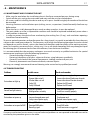
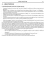
4.2 TROUBLESHOOTING
Problems Possible causes Checks and remedies
Fixture does not light up
• No mains supply
• Dimmer fader set to 0
• All color faders set to 0
• Faulty LED
• Faulty LED board
• Check the power supply voltage
• Increase the value of the dimmer channels
• Increase the value of the color channels
• Replace the LED board
• Replace the LED board
General low light intensity
• Dirty lens assembly
• Misaligned lens assembly
• Clean the xture regularly
• Install lens assembly properly
Fixture does not power up
• No power
• Loose or damaged power cord
• Faulty internal power supply
• Check for power on power outlet
• Check power cord
• Replace internal power supply
Fixture does not respond to DMX
• Wrong DMX addressing
• Damaged DMX cables
• Bouncing signals
• Check control panel and unit addressing
• Check DMX cables
• Install terminator as suggested
Contact an authorized service center in case of technical problems or not reported in the table can not be
resolved by the procedure given in the table.

REV.002-12/18
Music & Lights S.r.l. si riserva ogni diritto di elaborazione in qualsiasi forma delle presenti istruzioni per l’uso.
La riproduzione - anche parziale - per propri scopi commerciali è vietata.
Al ne di migliorare la qualità dei prodotti, la Music&Lights S.r.l. si riserva la facoltà di modicare, in qualun-
que momento e senza preavviso, le speciche menzionate nel presente manuale di istruzioni.
Tutte le revisioni e gli aggiornamenti sono disponibili nella sezione 'Manuali' sul sito www.musiclights.it
La pagina si sta caricando...
La pagina si sta caricando...
La pagina si sta caricando...
La pagina si sta caricando...
La pagina si sta caricando...
La pagina si sta caricando...
La pagina si sta caricando...
La pagina si sta caricando...
La pagina si sta caricando...
La pagina si sta caricando...
La pagina si sta caricando...
La pagina si sta caricando...
La pagina si sta caricando...
La pagina si sta caricando...
La pagina si sta caricando...
La pagina si sta caricando...
La pagina si sta caricando...
La pagina si sta caricando...
La pagina si sta caricando...
La pagina si sta caricando...
-
 1
1
-
 2
2
-
 3
3
-
 4
4
-
 5
5
-
 6
6
-
 7
7
-
 8
8
-
 9
9
-
 10
10
-
 11
11
-
 12
12
-
 13
13
-
 14
14
-
 15
15
-
 16
16
-
 17
17
-
 18
18
-
 19
19
-
 20
20
-
 21
21
-
 22
22
-
 23
23
-
 24
24
-
 25
25
-
 26
26
-
 27
27
-
 28
28
-
 29
29
-
 30
30
-
 31
31
-
 32
32
-
 33
33
-
 34
34
-
 35
35
-
 36
36
-
 37
37
-
 38
38
-
 39
39
-
 40
40


ProLights SOLAR27Q Manuale utente
- Categoria
- Stroboscopi
- Tipo
- Manuale utente
in altre lingue
- English: ProLights SOLAR27Q User manual
Documenti correlati
-
ProLights IP65 160 W zoomable LED ellipsoidal Manuale utente
-
-
-
-
-
-
-
-
-