Olimpia Splendid Bi2 SL inverter Guida d'installazione
- Categoria
- Bilance da cucina
- Tipo
- Guida d'installazione
Questo manuale è adatto anche per
La pagina si sta caricando...

GB
F
D
2
I
4
4
4
4
6
8
10
12
16
16
18
18
20
22
22
22
24
24
24
26
28
30
30
32
34
34
34
36
38
40
40
42
44
46
46
48
48
50
50
52
1 GENERALITA’
1.1 INFORMAZIONI
GENERALI
1.1.1 Conformità
1.1.2 Simbologia
1.3 AVVERTENZE GENERALI
1.4 REGOLE FONDAMENTALI
DI SICUREZZA
1.5 GAMMA PRODOTTI
1.6 CONOSCIAMO IL Bi2+
1.7 DIMENSIONI
D’INGOMBRO Bi2+ 2 TUBI
1.8 CARATTERISTICHE
TECNICHE NOMINALI
VERSIONE Bi2+ 2 TUBI
2
INSTALLAZIONE
2.1 POSIZIONAMENTO
DELL’UNITA’
2.2 MODALITA’ DI
INSTALLAZIONE
2.3 DISTANZE MINIME DI
INSTALLAZIONE
2.4 APERTURA FIANCHI
2.5 INSTALLAZIONE A
PARETE O PAVIMENTO
VERTICALE
2.6 INSTALLAZIONE
A SOFFITTO O
ORIZZONTALE
2.7 COLLEGAMENTI
IDRAULICI
2.7.1 Diametro tubazioni
2.7.2 Collegamenti
2.8 SCARICO CONDENSA
2.8.1 Montaggio del dispositivo
di scarico della condensa
nella versione verticale
2.8.2 Montaggio del dispositivo
di scarico della condensa
nella versione orizzontale
2.9 ROTAZIONE ATTACCHI
2.9.1 Smontaggio pannellature
2.9.2 Smontaggio pannello
radiante (solo per modello
SLR+)
2.9.3 Smontaggio pannello di
comando (se presente)
2.9.4 Smontaggio scambiatori
2.10 MONTAGGIO SOSTEGNO
SICUREZZA GRIGLIA
ANTERIORE
2.11 RIEMPIMENTO IMPIANTO
2.12 EVACUAZIONE DELL’ARIA
DURANTE IL RIEMPIMENTO
DELL’IMPIANTO
2.13 MANUTENZIONE
2.14 PULIZIA ESTERNA
2.15 PULIZIA FILTRO
ASPIRAZIONE ARIA
(VWUD]LRQHFHOOH¿OWUDQWL
nelle versioni con griglia
aspirazione ad alette
3XOL]LDVHWWL¿OWUDQWL
2.15.3 Termine operazioni di
pulizia
2.16 CONSIGLI PER
IL RISPARMIO
ENERGETICO
3
ANOMALIE E RIMEDI
3.1 TABELLA DELLE
ANOMALIE E DEI RIMEDI
1
GENERAL
1.1 GENERAL INFORMATION
1.1.1 Conformity
1.1.2 Symbols
1.3 GENERAL WARNINGS
1.4 FUNDAMENTAL SAFETY
RULES
1.5 PRODUCT RANGE
1.6 MORE ABOUT THE Bi2+
1.7 OVERALL DIMENSIONS
Bi2+ 2 PIPES
1.8 NOMINAL TECHNICAL
CHARACTERISTICS Bi2+
2 PIPE VERSION
2
INSTALLATION
2.1 POSITIONING THE UNIT
2.2 INSTALLATION MODES
2.3 MINIMUM INSTALLATION
DISTANCES
2.4 SIDE OPENING
2.5 VERTICAL FLOOR OR
WALL INSTALLATION
2.6 HORIZONTAL OR
CEILING INSTALLATION
2.7 HYDRAULIC
CONNECTIONS
2.7.1 Pipeline diameter
2.7.2 Connections
2.8 CONDENSATION
DISCHARGE
2.8.1 Mounting the condensation
discharge device in the
vertical version
2.8.2 Mounting the condensation
discharge device in the
horizontal version
2.9 FIXTURE ROTATION
2.9.1 Dismounting panels
2.9.2 Dismounting the radiant
plate (SLR+ model only)
2.9.3 Dismounting control panel
(if present)
2.9.4 Dismounting exchangers
2.10 MOUNTING FRONT
GRILL SAFETY SUPPORT
2.11 FILLING THE SYSTEM
2.12 EVACUATING AIR WHILE
FILLING THE SYSTEM
2.13 MAINTENANCE
2.14 CLEANING THE OUTSIDE
2.15 CLEANING AIR SUCTION
FILTER
([WUDFWLRQRI¿OWHUFHOOVLQ
the versions with aspiration
JULOOZLWKÀDSV
&OHDQLQJ¿OWHULQJVHDWV
2.15.3 Ending Cleaning
Operations
2.16 ENERGY SAVING TIPS
3
TROUBLESHOOTING
3.1 TABLE OF ANOMALIES
AND REMEDIES
1
GENERALITES
1.1 INFORMATIONS
GENERALES
1.1.1 Conformité
1.1.2 Symboles
1.3 AVERTISSEMENT
GENERAUX
1.4 REGLES
FONDAMENTALES DE
SECURITE
1.5 GAMME DE PRODUITS
1.6 DECOUVRONS LE Bi2+
1.7 DIMENSIONS HORS
TOUT Bi2+ 2 TUBES
1.8 CARACTERISTIQUES
TECHNIQUES
NOMINALES VERSION
Bi2+ 2 TUBES
2
INSTALLATION
2.1 MISE EN PLACE DE
L’UNITE
2.2 MODALITES
D’INSTALLATION
2.3 DISTANCES MINIMUM
D’INSTALLATION
2.4 OUVERTURE FLANCS
2.5 INSTALLATION MURALE
OU AU SOL VERTICALE
2.6 INSTALLATION
AU PLAFOND OU
HORIZONTALE
2.7 BRANCHEMENTS
HYDRAULIQUES
2.7.1 Diamètre tubes
2.7.2 Branchements
2.8 EVACUATION DES
CONDENSATS
2.8.1 Montage du dispositif
d’évacuation des
condensats dans la version
verticale
2.8.2 Montage du dispositif
d’évacuation des
condensats dans la version
horizontale
2.9 ROTATION DES
FIXATIONS
2.9.1 Démontage des panneaux
2.9.2 Démontage de la plaque
rayonnante (uniquement
pour le modèle SLR+)
2.9.3 Démontage du panneau de
commande (si présent)
2.9.4 Démontage des
échangeurs
2.10 MONTAGE DU SUPPORT
DE SECURITE GRILLE
AVANT
2.11 REMPLISSAGE DU
CIRCUIT
2.12 PURGE DE L’AIR
PENDANT LE
REMPLISSAGE DU
CIRCUIT
2.13 ENTRETIEN
2.14 NETTOYAGE EXTERNE
2.15 NETTOYAGE FILTRE
ASPIRATION AIR
2.15.1 Enlèvement des cellules
¿OWUDQWHVVXUOHVYHUVLRQVj
grille d’aspiration à ailettes
2.15.2 Nettoyage des éléments
¿OWUDQWV
2.15.3 Fin des opérations de
nettoyage
2.16 CONSEILS POUR LES
ECONOMIES D’ENERGIE
3
ANOMALIES ET
REMEDES
3.1 TABLEAU DES
ANOMALIES ET DES
REMEDES
1
ALLGEMEINES
1.1 ALLGEMEINE
INFORMATIONEN
1.1.1 Konformität
1.1.2 Symbolgebung
1.3 ALLGEMEINE HINWEISE
1.4 GRUNDLEGENDE
SICHERHEITSREGELN
1.5 PRODUKTPALETTE
1.6 Bi2+ KENNEN
1.7 AUSSENABMESSUNGEN
Bi2+ 2 SCHLÄUCHE
1.8 TECHNISCHE NENN-
EIGENSCHAFTEN
AUSFÜHRUNG Bi2+ / 2
SCHLÄUCHE
2
INSTALLATION
2.1 POSITIONIERUNG DER
EINHEIT
2.2 INSTALLATIONSWEISE
2.3 MINDEST-
INSTALLATIONSABSTÄNDE
2.4 ÖFFNUNG DER SEITEN
2.5 INSTALLATION AN
DER WAND ODER AM
FUSSBODEN / VERTIKAL
2.6 INSTALLATION AN
DER DECKE ODER
HORIZONTAL
2.7 WASSERANSCHLÜSSE
2.7.1 Durchmesser der
Schlauch-/Rohrleitungen
2.7.2 Anschlüsse
2.8 KONDENSWASSERABFLUSS
2.8.1 Montage der
Kondenswasserabflussvorrichtung
in der Ausführung
2.8.2 Montage der
Kondenswasserabflussvorrichtung
in der Ausführung
2.9 DREHUNG DER
ANSCHLÜSSE
2.9.1 Ausbau der Verkleidungen
2.9.2 Ausbau der Strahlplatte
(nur bei Modell SLR+)
2.9.3 Ausbau der Bedientafel
(falls vorhanden)
2.9.4 Ausbau der
Wärmetauscher
2.10 MONTAGE DER
SICHERUNGSHALTERUNG
FÜR DEN VORDEREN
ROST
2.11 FÜLLEN DER ANLAGE
2.12 AUSLEITEN DER
LUFT WÄHREND DES
FÜLLENS DER ANLAGE
2.13 WARTUNG
2.14 Außenreinigung
2.15 REINIGUNG DES
LUFTANSAUGFILTERS
2.15.1 Ausziehen der Filterzellen
in den Ausführungen mit
geripptem Saugrost
2.15.2 Reinigung der
Filtereinsätze
2.15.3 Ende der
Reinigungsarbeiten
2.16 ENERGIESPARHINWEISE
3 STÖRUNGEN UND
BEHELFE
3.1 TABELLE DER
STÖRUNGEN UND
BEHELFE
La pagina si sta caricando...

GB
F
D
4
I
1
GENERALITA’
INFORMAZIONI GENERALI
Grazie per aver scelto un
ventil-radiatore ventilconvettore
Olimpia Splendid Bi2+ per la
climatizzazione dei vostri ambienti.
Vi invitiamo a leggere questo
manuale d’uso e installazione
attentamente prima di installare e
mettere in funzione l’apparecchio.
Seguendo i suggerimenti riportati
riuscirete a mantenere nel
tempo inalterate le prestazioni
dell’apparecchio. In conformità
alla normativa europea 99/44/EEC
la ditta costruttrice garantisce la
macchina 24 mesi dalla data di acquisto
(fatto salve eventuali estensioni di
garanzia commerciale) per difetti
imputabili a vizi di fabbricazione. Resta
escluso qualsiasi altro problema
legato a errata installazione,
eventi atmosferici straordinari,
dimensionamento non conforme e
manomissioni non autorizzate.
Conformità
I ventil-radiatori/ventilconvettori
Bi2+ OLIMPIA SPLENDID sono
conformi alle Direttive Europee:
'LUHWWLYDEDVVDWHQVLRQH
EC: EN 60335-1:2002 + A11:2004
+ A1:2004 + A12:2006 + A2:2006
+ A13:2008; EN 60335-2-40:2003
+ A11:2004 + A12:2005 + A1:2006
+ A2:2009; EN 62233:2008.
'LUHWWLYD FRPSDWLELOLWj
elettromagnetica 2004/108/EC:
EN 55014-1:2006 + A1:2009;
EN 55014-2:1997 + A1:2001 +
A2:2008; EN 61000-3-2:2006 +
A2:2009 + A1:2009; EN 61000-
3-3:2008.
In ogni caso, essendo incorporati
all'interno dell'impianto, la conformità
dei ventil-radiatori / ventilconvettori
QHOOLQVWDOOD]LRQH VSHFL¿FD GRYUj
essere verificata e garantita
dall'installatore in ottemperanza
alle leggi e ai regolamenti applicabili.
Simbologia
I pittogrammi riportati nel seguente
capitoloconsentono di fornire
rapidamente ed in modo univoco
informazioni necessarie alla corretta
utilizzazione della macchina in
condizioni di sicurezza.
Indice
- I paragrafi preceduti da
questo simbolo contengono
informazioni e prescrizioni molto
importanti, particolarmente per
quanto riguarda la sicurezza.
Il mancato rispetto può comportare:
- pericolo per l’incolumità degli
operatori
- perdita della garanzia contrattuale
- declinazione di responsabilità da
parte della ditta costruttrice.
1
1.1
1.1.1
1.1.2
GENERAL
GENERAL INFORMATION
Thank you for choosing an Olimpia
Splendid Bi2+ cooler-radiator/
cooler-convector for controlling the
climate in your home. Please read
this instruction use and installation
manual carefully before installing
and starting up the appliance.
Following the indications contained
in this manual will ensure that the
appliance continues to function
perfectly over time. In compliance
with European standard 99/44/
EEC the manufacturer guaranteed
the machine for 24 months from
the date of purchase (except for
any warranty extensions) against
any defects that can be attributed
to manufacturing defects. Excluded
are all other problems linked to
incorrect installation, extraordinary
atmospheric events, non-compliant
dimensioning or unauthorised
interventions.
Conformity
The OLIMPIA SPLENDID Bi2+
cooler-radiator/cooler-convectors
conform to the following European
Directives:
/RZWHQVLRQGLUHFWLYH(&
EN 60335-1:2002 + A11:2004 +
A1:2004 + A12:2006 + A2:2006 +
A13:2008; EN 60335-2-40:2003 +
A11:2004 + A12:2005 + A1:2006
+ A2:2009; EN 62233:2008.
(OHFWURPDJQHWLF FRPSDWLELOLW\
2004/108/EC: EN 55014-1:2006
+ A1:2009; EN 55014-2:1997 +
A1:2001 + A2:2008; EN 61000-
3-2:2006 + A2:2009 + A1:2009;
EN 61000-3-3:2008.
In any case, as they are built into the
system, the compliance of the ventil
UDGLDWRUVIDQ FRLOV LQ WKH VSHFL¿F
LQVWDOODWLRQ PXVW EH YHUL¿HG DQG
guaranteed by the installer in order
to comply with the applicable laws
and regulations.
Symbols
The pictograms in the next chapter
provide the necessary information
for correct, safe use of the machine
in a rapid, unmistakable way.
Index
- Paragraphs marked with this
symbol contain very important in-
formation and recommendations,
particularly as regards safety.
Failure to comply with them may
result in:
- danger of injury to the operators
- loss of the warranty
- refusal of liability by the manufac-
turer.
GENERALITES
INFORMATIONS GENERALES
Merci d’avoir choisi un ventilateur-
radiateur/ventilateur-convecteur
Olimpia Splendid Bi2+ pour la
climatisation de vos pièces. Nous
vous invitons à lire le présent
manuel d’utilisation et d’installation
attentivement avant d’installer et
de mettre en fonction l’appareil. En
suivant les suggestions fournies, vous
parviendrez à garder inchangées au
cours du temps les performances de
l’appareil. Conformément à la norme
européenne 99/44/EEC, l’entreprise
constructrice garantit la machine
pendant 24 mois à compter de la date
d’achat (sous réserve des éventuelles
extensions de garantie commerciale)
pour les défauts imputables à des
vices de fabrication. Reste exclu
tout autre problème lié à une
mauvaise installation, événements
atmosphériques extraordinaires,
dimensionnement non conforme et
altérations non autorisées.
Conformité
Les ventilateurs-radiateurs/
ventilateurs-convecteurs Bi2+
OLIMPIA SPLENDID sont conformes
aux directives européennes:
'LUHFWLYHEDVVHWHQVLRQ
EC: EN 60335-1:2002 + A11:2004
+ A1:2004 + A12:2006 + A2:2006
+ A13:2008; EN 60335-2-40:2003
+ A11:2004 + A12:2005 + A1:2006
+ A2:2009; EN 62233:2008.
'LUHFWLYH FRPSDWLELOLWp
électromagnétique 2004/108/
EC: EN 55014-1:2006 + A1:2009;
EN 55014-2:1997 + A1:2001 +
A2:2008; EN 61000-3-2:2006 +
A2:2009 + A1:2009; EN 61000-
3-3:2008.
Dans tous les cas, étant incorporés à
l’intérieur du système, la conformité
des ventilateurs radiateurs /
ventilateurs convecteurs au système
VSpFL¿TXH GHYUD rWUH YpUL¿pH HW
garantie par l’installateur selon les
lois et les règlements en vigueur.
Symbologie
Les pictogrammes reportés au cha-
pitre suivant permettent de fournir
rapidement et de manière univoque
les informations nécessaires pour
une utilisation correcte de la machine
dans des conditions de sécurité.
Index
- Les paragraphes précédés par ce
symbole contiennent des infor-
mations et des prescriptions très
importantes, notamment pour ce
qui concerne la sécurité.
Le non-respect peut comporter:
- danger pour la sécurité des
opérateurs.
- perte de la garantie du contrat.
- dégagement de la responsabilité
du fabricant.
ALLGEMEINES
ALLGEMEINE INFORMATIONEN
Wir bedanken uns dafür, dass Sie
sich für einen Olimpia Splendid Bi2+
Ventil-Radiator/Ventil-Konvektor
zur Klimatisierung Ihrer Räume
entschieden haben. Bitte lesen
Sie dieses Bedienungs- und
Wartungshandbuch sorgfältig,
bevor Sie das Gerät installieren und
in Betrieb nehmen. Wenn Sie die
enthaltenen Anweisungen befolgen,
bleiben die Betriebsleistungen
des Geräts auf Dauer erhalten.
In Übereinstimmung mit der
Europanorm 99/44/EWG gewähr
GLH +HUVWHOOHU¿UPD HLQH *DUDQWLH
von 24 Monaten ab Kaufdatum
(mit der Möglichkeit eventueller
Handelsgarantie-Erweiterungen)
auf Fertigungsmängel der
Maschine. Alle weiteren,
auf fehlerhafte Installation,
außergewöhnliche atmosphärische
Ereignisse, unsachgemäße
Bemessung sowie unerlaubte
Öffnungen des Geräts
zurückzuführende Anomalien sind
von der Garantie ausgeschlossen.
Konformität
Die Ventil-Radiatoren/
Ventil-Konvektoren Bi2+
OLIMPIA SPLENDID stehen
in Übereinstimmung mit den
Europarichtlinien:
1LHGHUVSDQQXQJVULFKWOLQLH
2006/95/EC: EN 60335-1:2002
+ A11:2004 + A1:2004 + A12:2006
+ A2:2006 + A13:2008; EN
60335-2-40:2003 + A11:2004 +
A12:2005 + A1:2006 + A2:2009;
EN 62233:2008.
5LFKWOLQLH]XUHOHNWURPDJQHWLVFKHQ
Verträglichkeit 2004/108/EC: EN
55014-1:2006 + A1:2009; EN
55014-2:1997 + A1:2001 +
A2:2008; EN 61000-3-2:2006 +
A2:2009 + A1:2009; EN 61000-
3-3:2008.
Da die Ventil-Radiatoren / Ventil-
Konvektoren in die Anlage eingebaut
werden, ist In jedem Fall die
Konformität der Geräte in der
VSH]L¿VFKHQ ,QVWDOODWLRQ]X SUIHQ
und vom Monteur den geltenden
Gesetzen und Reglements gemäß
zu garantieren.
Bildsymbole
Die im folgenden Kapitel aufgeführten
Bildsymbole liefern schnell und
eindeutig Informationen zum
korrekten und sicheren Gebrauch
des Gerätes.
Inhaltsverzeichnis
- Die Paragrafen, denen dieses
Symbol vorausgeht, enthalten
sehr wichtige Informationen
und Vorschriften, insbesondere
bezüglich der Sicherheit.
Die Nichtbeachtung dieser
Informationen und Vorschriften
kann dazu führen, dass:
- die Unversehrtheit des
Personals an den Geräten
gefährdet ist
- die vertragliche Garantie
verfällt
- die Herstellerfirma jede
Verantwortung ablehnt.
La pagina si sta caricando...

GB
F
D
6
I
1
1.3
Pericolo generico
- che l’operazione descritta
presenta, se non effettuata
nel rispetto delle normative di
sicurezza, il rischio di subire
GDQQL¿VLFL
AVVERTENZE GENERALI
Dopo aver tolto l’imballo
assicurarsi dell’integrità e della
completezza del contenuto.
In caso di non rispondenza
rivolgersi all’Agenzia OLIMPIA
SPLENDID che ha venduto
l’apparecchio.
L’installazione degli apparecchi
OLIMPIA SPLENDID deve
essere effettuata da impresa
DELOLWDWDFKHD¿QHODYRURULODVFLDO
responsabile dell’impianto una
dichiarazione di conformità
in ottemperanza alle Norme
vigenti ed alle indicazioni fornite
dalla OLIMPIA SPLENDID nel
libretto d’istruzione a corredo
dell’apparecchio.
Questi apparecchi sono stati
realizzati per il condizionamento
e/o il riscaldamento degli
ambienti e dovranno essere
destinati a questo uso
compatibilmente con le loro
caratteristiche prestazionali.
È esclusa qualsiasi responsabilità
contrattuale ed extracontrattuale
della OLIMPIA SPLENDID per
danni causati a persone, animali
o cose, da errori di installazione,
di regolazione e di manutenzione
o da usi impropri.
In caso di fuoriuscite di acqua,
posizionare l’interruttore
generale dell’impianto su
³VSHQWR´ H FKLXGHUH L UXELQHWWL
dell’acqua.
Chiamare, con sollecitudine, il
Servizio Tecnico di Assistenza
OLIMPIA SPLENDID, oppure
personale professionalmente
qualificato e non intervenire
personalmente sull’apparecchio.
Nell’installazione del Bi2 è
necessario garantire la non
accessibilità della zona
posteriore dell’apparecchio.
Nei casi in cui ciò non sia
garantito dalla parete o dal
VRI¿WWRqREEOLJDWRULRXWLOL]]DUH
il kit di chiusura posteriore
disponibile come accessorio.
Il non utilizzo dell’apparecchio
per un lungo periodo comporta
l’effettuazione delle seguenti
operazioni:
- Posizionare l’interruttore
generale dell’impianto su
³VSHQWR´
- Chiudere i rubinetti dell’acqua
- Se c’è pericolo di gelo, accer-
tarsi che l’impianto sia stato
addizionato con del liquido
antigelo, altrimenti vuotare
l’impianto.
Generic danger
- Signals to the personnel that the
operation described could cause
physical injury if not performed
according to the safety rules.
GENERAL WARNINGS
After unpacking, make sure that
all the components are present.
If not, contact the OLIMPIA
SPLENDID agent who sold the
appliance to you.
OLIMPIA SPLENDID appliances
must be installed by an authorised
installer who, on completion of the
work, will release a declaration
of conformity to the client in
respect of the laws in force and
the indications given by OLIMPIA
SPLENDID in the instructions
OHDÀHWVXSSOLHGWRJHWKHUZLWKWKH
appliance.
These appliances have been
designed both for conditioning
and/or heating environments
and must be destined for this
use only and compatibly with
their performance characteristics.
OLIMPIA SPLENDID accepts no
responsibility, either contractual
or extra-contractual, for any
damage caused to persons,
animals of property as a result of
incorrect installation, adjustment
or maintenance or improper use.
In case of water leaks, turn the
master switch of the system to
“OFF” and close the water taps.
As soon as possible, call
the OLIMPIA SPLENDID
technical service department
RU HOVH SURIHVVLRQDOO\ TXDOL¿HG
personnel and do not intervene
personally on the appliance.
In the Bi2 installation,
inaccessibility to the rear of the
appliance must be guaranteed.
In the event this is not guaranteed
by the wall or ceiling, it is
obligatory to use the rear closure
kit available as an accessory.
If the appliance is not used for a
log period of time, the following
operations should be performed:
- Turn the master switch of the
system to “OFF”
- Close the water taps
- If there is the risk of freezing,
make sure that anti-freeze
has been added to the system
otherwise empty the system.
Danger général
- Signale au personnel concerné
que l’opération décrite présen-
te, si elle n’est pas effectuée
conformément aux normes de
sécurité, le risque de provoquer
des dommages physiques.
AVERTISSEMENT GENERAUX
Après avoir enlevé l’emballage,
s’assurer de l’intégrité et du
caractère complet du contenu.
En cas de non conformité,
s’adresser à l’agence OLIMPIA
SPLENDID qui a vendu l’appareil.
L’installation des appareils
2/,03,$ 63/(1',' GRLW rWUH
effectuée par une entreprise
KDELOLWpH TXL HQ ¿Q GH WUDYDLO
doit remettre au
responsable de l’équipement une
déclaration de conformité selon
les normes en vigueur et les
indications fournies par OLIMPIA
SPLENDID dans le manuel
d’utilisation accompagnant
l’appareil.
Ces appareils ont été réalisés
pour la climatisation et/ou le
chauffage des pièces, et ils
GRLYHQWrWUHGHVWLQpVjFHWXVDJH
de façon compatible avec leurs
performances.
Toute responsabilité tant
contractuelle qu’extracontractuelle
d’OLIMPIA SPLENDID est exclue
pour les dommages causés à des
personnes, des animaux ou des
biens par des erreurs d’installation,
de réglage ou d’entretien, ou par un
usage non approprié.
En cas de fuites d’eau, amener
l’interrupteur général de
O¶DSSDUHLOVXU³pWHLQW´ HW IHUPHU
les robinets d’eau.
Appeler dans les meilleurs délais
le Service technique d’assistance
OLIMPIA SPLENDID, ou bien du
personnel professionnellement
qualifié et ne pas intervenir
personnellement sur l’appareil.
Sur le système Bi2 il est
nécessaire de garantir la non
accessibilité de la zone arrière
de l’appareil.
Dans les cas où cela n’est pas
garanti par le mur ou le plafond,
il est obligatoire d’utiliser le kit
de fermeture arrière disponible
comme accessoire.
L’inutilisation prolongée de
l’appareil nécessite la réalisation
des opérations suivantes:
- Amener l’interrupteur général
GHO¶DSSDUHLOVXU³pWHLQW´
- Fermer les robinets d’eau
- S’il y a danger de gel, s’assurer
que le circuit a été additionné
de liquide antigel, sinon vider
le circuit.
Allgemeine Gefahr
- Zeigt dem betreffenden Personal
an, dass bei der beschriebenen
Tätigkeit Verletzungsgefahr besteht,
wenn diese nicht unter Beachtung
der Sicherheitsvorschriften
durchgeführt wird.
ALLGEMEINE HINWEISE
Stellen Sie nach Entfernung der
Verpackung die Unversehrtheit
und Vollständigkeit des Inhalts
sicher. Wenden Sie sch bei
Unstimmigkeiten an die OLIMPIA
SPLENDID Niederlassung, bei
der Sie das Gerät gekauft haben.
Die Installation der OLIMPIA
SPLENDID Geräte ist durch
HLQH)DFK¿UPDDXV]XIKUHQGLH
bei Abschluss der Arbeiten dem
Verantwortlichen der Anlage
eine Erklärung zur Konformität
in Übereinstimmung mit den
geltenden Vorschriften und den
von OLIMPIA SPLENDID in
diesem Handbuch festgesetzten
Anweisungen übergibt.
Diese Geräte wurden zur
Klimatisierung und/oder Heizung
von Räumen hergestellt und
sind ausschließlich für mit ihren
Leistungsdaten verträgliche
Zwecke einzusetzen.
Jegliche vertragliche oder
außervertragliche Haftung
seitens OLIMPIA SPLENDID
für Schäden an Personen,
Tieren oder Gegenständen
aufgrund fehlerhafter Installation,
Einstellung, Wartung oder
unsachgemäßen Gebrauchs ist
ausgeschlossen.
Stellen Sie beim Austreten von
Wasser den Hauptschalter der
Anlage auf “Aus” und schließen
Sie die Wasserhähne.
Rufen Sie unverzüglich den
Technischen Kundendienst
von OLIMPIA SPLENDID oder
entsprechendes Fachpersonal
und greifen Sie nicht selbst am
Gerät ein.
Bei der Installation des Bi2 ist
die Nichtzugänglichkeit des
hinteren Bereiches des Geräts
zu gewährleisten.
Wenn dies nicht von der Wand
oder der Decke garantiert
wird, ist es obligatorisch, das
als Zubehör erhältliche Kit für
den hinteren Verschluss zu
verwenden.
Bei Nichtbenutzung des Geräts
für einen langen Zeitraum sind
folgende Schritte durchzuführen:
- Stellen Sie den Hauptschalter
der Anlage auf “Aus”
- Schließen Sie die
Wasserhähne.
- Bei Frostgefahr vergewissern
Sie sich, dass die
Frostschutzmittel in die Anlage
gegeben wurde. Andernfalls
entleeren Sie die Anlage.
La pagina si sta caricando...

GB
F
D
8
I
1
E’ necessario che l’impianto
elettrico sia realizzato nel pieno
rispetto delle norme e dei
regolamenti applicabili, sia dotato
GLXQ¶HI¿FDFHFRQQHVVLRQHGLWHUUD
e di adeguate protezioni contro
sovraccarichi e/o cortocircuiti.
Si consiglia di inserire una
disconnessione onnipolare e una
opportuna protezione elettrica
sulla linea di alimentazione di
ciascun apparecchio installato.
Una temperatura troppo bassa
o troppo alta (a seconda della
modalità di funzionamento) è
dannosa alla salute e costituisce
un inutile spreco di energia.
Evitare il contatto diretto con il
ÀXVVR GHOO¶DULD SHU XQ SHULRGR
prolungato.
Evitare che il locale rimanga
chiuso a lungo. Periodicamente
DSULUHOH¿QHVWUHSHUDVVLFXUDUH
un corretto ricambio d’aria.
Questo libretto d’istruzione è
parte integrante dell’apparecchio
e di conseguenza deve essere
conservato con cura e dovrà
SEMPRE accompagnare
l’apparecchio anche in caso
di sua cessione ad altro
proprietario o utente oppure
di un trasferimento su un
altro impianto. In caso di suo
danneggiamento o smarrimento
richiederne un altro esemplare al
Servizio Tecnico di Assistenza
OLIMPIA SPLENDID di zona.
Gli interventi di riparazione o
manutenzione devono essere
eseguiti dal Servizio Tecnico
di Assistenza o da personale
qualificato secondo quanto
previsto dal presente libretto.
1RQPRGL¿FDUHRPDQRPHWWHUH
l’apparecchio in quanto si
possono creare situazioni di
pericolo ed il costruttore
dell’apparecchio non sarà
responsabile di eventuali danni
provocati.
REGOLE FONDAMENTALI DI
SICUREZZA
Ricordiamo che l’utilizzo di
prodotti che impiegano energia
elettrica ed acqua, comporta
l’osservanza di alcune regole
fondamentali di sicurezza quali:
È vietato l’uso dell’apparecchio
ai bambini e alle persone inabili
non assistite.
È vietato toccare l’apparecchio
se si è a piedi nudi e con parti del
corpo bagnate o umide.
1.4
The electrical system must be
made in full compliance with the
applicable laws and regulations,
it must be earthed and have
adequate protection against
overloads and/or short-circuits.
Installation of an omnipolar
disconnection switch and
suitable electrical protection is
advisable on the power line of
each appliance installed.
An excessively high or low
temperature (depending on the
operating mode) is harmful to
the health and wastes energy
needlessly.
Avoid prolonged contact with the
GLUHFWDLUÀRZ
Do not leave the room closed for
long periods. Periodically open
the windows to ensure a correct
change of air.
This instruction leaflet is an
integral part of the appliance
and consequently must be kept
carefully and must ALWAYS
accompany the appliance,
even when it is passed to a new
owner or user or transferred
onto another system. If it is lost
or damaged, please contact
the local OLIMPIA SPLENDID
technical service centre.
All repair or maintenance
interventions must be performed
by the technical service
department or by professionally
TXDOL¿HGSHUVRQQHODVIRUHVHHQ
in this booklet. Do not modify
or intervene on the appliance
as this could create dangerous
situations and the manufacturer
will not be responsible for any
damage caused.
FUNDAMENTAL SAFETY
RULES
Remember that some
fundamental safety rules should
be followed when using a product
that uses electricity and water,
such as:
It is forbidden for the appliance to
be used by children or unassisted
disabled persons.
It is forbidden to touch the
appliance with wet hands or body
when barefoot.
Il est nécessaire que l’équipement
électrique soit réalisé dans le
respect total des normes et des
règlements en vigueur, soit doté
G¶XQH PLVH j OD WHUUH HI¿FDFH
et de protections appropriées
contre les surcharges et / ou les
courts-circuits.
Il est conseillé d’insérer une
déconnexion omnipolaire et une
protection électrique appropriée
sur la ligne d’alimentation de
chaque appareil installé
Une température trop basse ou
trop élevée (selon les modes de
fonctionnement) est nuisible à
la santé et constitue une perte
inutile d’énergie.
Eviter le contact direct prolongé
DYHFOHÀX[G¶DLU
Eviter que la pièce reste fermée
pendant longtemps. Ouvrir
UpJXOLqUHPHQWOHVIHQrWUHVSRXU
assurer un renouvellement d’air
correct.
Le présent manuel d’utilisation
fait partie intégrante de l’appareil
est doit par conséquent
rWUH FRQVHUYp DYHF VRLQ HW
TOUJOURS accompagner
O¶DSSDUHLO PrPH HQ FDV GH
cession de ce dernier à un
autre propriétaire ou utilisateur
ou bien de transfert sur une
autre installation. En cas de
détérioration ou de perte
du manuel, il convient d’en
demander un autre exemplaire
au Service technique
d’assistance OLIMPIA
SPLENDID secteur.
Les interventions de réparation
RX G¶HQWUHWLHQ GRLYHQW rWUH
effectuées par le Service
technique d’assistance ou par
du personnel
TXDOL¿p VHORQ OHV LQGLFDWLRQV
du présent manuel. Ne pas
modifier ou altérer l’appareil
car cela pourrait créer des
situations de danger et le
fabricant de l’appareil n’est
pas responsable des éventuels
dommages provoqués.
REGLES FONDAMENTALES
DE SECURITE
Rappelons que l’utilisation de
produits employant de l’énergie
électrique et de l’eau nécessite
le respect de quelques règles
fondamentales de sécurité,
telles que:
L’utilisation de l’appareil par
des enfants et des personnes
handicapées non assistées est
interdite.
Il est défendu de toucher
l’appareil pieds nus ou si des
parties du corps sont mouillées
ou humides.
Es ist notwendig, dass die
elektrische Anlage unter voller
Einhaltung der geltenden Normen
und Vorschriften ausgeführt
wird und mit einer wirksamen
Erdung sowie ausreichenden
Überlastungs- und/oder
Kurzschlussvorrichtungen
ausgestattet ist.
(V HPS¿HKOW VLFK GHU (LQVDW]
einer allpoligen Trennung
sowie eines passenden
elektrischen Schutzes auf
der Versorgungsleitung jedes
installierten Gerätes.
Eine zu niedrige oder
zu hohe Temperatur (je
nach Betriebsmodus) ist
gesundheitsschädlich
und stellt eine unnütze
Energieverschwendung dar.
Vermeiden Sie den direkten
Kontakt mit dem Luftstrom für
einen längeren Zeitraum.
Vermeiden Sie, dass der Raum
für einen längeren Zeitraum
geschlossen bleibt. Öffnen Sie
regelmäßig die Fenster, um
einen korrekten Luftaustausch
zu gewährleisten.
Diese Bedienungsanleitung
ist Bestandteil des Geräts
und entsprechend sorgfältig
aufzubewahren. Sie hat das
Gerät STETS zu begleiten,
auch bei Übergabe an einen
anderen Besitzer oder Anwender
oder bei Übertragung auf eine
andere Anlage. Fordern Sie
bei Beschädigung oder Verlust
ein anderes Exemplar beim
Technischen Kundendienst
von OLIMPIA SPLENDID Ihres
Gebietes an.
Reparatur- oder
Wartungseingriffe sind vom
technischen Kundendienst
oder durch Fachpersonal
den Vorschriften in diesem
Handbuch gemäß auszuführen.
Ändern oder öffnen Sie das
Gerät nicht, da es dabei zu
Gefährdungssituationen
kommen könnte und der
Hersteller des Gerätes nicht
für eventuell herbeigeführte
Schäden haftbar ist.
GRUNDLEGENDE
SICHERHEITSREGELN
Bitte beachten Sie, dass bei der
Verwendung von Produkten, die
elektrische Energie und Wasser
verbrauchen, die Einhaltung
einiger grundlegender Regeln
erforderlich ist, darunter:
Die Benutzung des Geräts
durch Kinder und ungeeignete,
nicht unterstützte Personen ist
verboten.
Die Berührung des Gerätes,
wenn Sie barfuß sind, oder
mit nassen oder feuchten
Körperteilen ist verboten.
La pagina si sta caricando...

GB
F
D
10
I
1.5
1
È vietata qualsiasi operazione di
pulizia, prima di aver scollegato
l’apparecchio dalla rete di
alimentazione elettrica
posizionando l’interruttore
generale dell’impianto su
³VSHQWR´
ÊYLHWDWRPRGL¿FDUHLGLVSRVLWLYL
di sicurezza o di regolazione
senza l’autorizzazione e le
indicazioni del costruttore
dell’apparecchio.
È vietato tirare, staccare, torcere
i cavi elettrici fuoriuscenti
dall’apparecchio, anche se
questo è scollegato dalla rete di
alimentazione elettrica.
È vietato introdurre oggetti e
sostanze attraverso le griglie di
aspirazione e mandata d’aria.
È vietato aprire gli sportelli
di accesso alle parti interne
dell’apparecchio, senza aver
prima posizionato l’interruttore
JHQHUDOHGHOO¶LPSLDQWRVX³VSHQWR´
È vietato disperdere e lasciare
alla portata di bambini il materiale
dell’imballo in quanto può essere
potenziale fonte di pericolo.
È vietato salire con i piedi
sull’apparecchio e/o appoggiarvi
qualsiasi tipo di oggetto.
L’apparecchio può raggiungere
temperature, sui componenti
esterni, superiori ai 70°C.
PRESTARE MOLTA
ATTENZIONE AL CONTATTO,
PERICOLO SCOTTATURE.
GAMMA PRODOTTI
I ventil-radiatori/ventilconvettori
della gamma Bi2+ si suddividono
in due tipologie base SL+ e
SLR+, ciascuna delle quali è
realizzata in cinque taglie di
diverse prestazioni e dimensioni
SL+
ventilconvettore (adatto per
installazioni orizzontali o
verticali).
SLR+
ventil-radiatore con pannello
radiante (adatto per installazioni
verticali).
It is forbidden to carry out
any cleaning before having
disconnected the appliance from
the electricity mains supply by
turning the system master switch
to “OFF”.
It is forbidden to modify the
safety or adjustment devices or
adjust without authorisation and
indications of the manufacturer.
It is forbidden to pull, cut or knot
the electrical cables coming out
of the appliance, even if it is
disconnected from the mains
supply.
It is forbidden to poke objects or
anything else through the inlet or
outlet grills.
It is forbidden to open the doors
which access the internal parts
RI WKH DSSOLDQFH ZLWKRXW ¿UVW
turning the system master switch
to “OFF”.
It is forbidden to dispose of or
leave in the reach of children the
packaging materials which could
become a source of danger.
It is forbidden to climb onto the
appliance or rest any object on it.
The external parts of the appliance
can reach temperatures of more
than 70°C.
DANGER FROM BURNS - TAKE
CARE WHEN TOUCHING
PRODUCT RANGE
The there are two basic types
of Bi2+ cooler-radiators/cooler-
convectors, SL+ and SLR+, each
RIZKLFKLVRIIHUHGLQ¿YHVL]HV
with different performances and
dimensions.
SL+
cooler-convector (suitable
for horizontal or vertical
installations).
SLR+
ventil radiator with radiant plate
(suitable for vertical installations).
Toute opération de nettoyage
est défendue, avant d’avoir
débranché l’appareil du réseau
d’alimentation électrique en
amenant l’interrupteur général
GHO¶DSSDUHLOVXU³pWHLQW´
,O HVW GpIHQGX GH PRGL¿HU OHV
dispositifs de sécurité ou de
réglage sans l’autorisation et
les indications du constructeur
de l’appareil.
Il est défendu de tirer, détacher,
tordre les câbles électriques
VRUWDQWGHO¶DSSDUHLOPrPHVLFH
dernier est débranché du réseau
d’alimentation électrique.
Il est défendu d’introduire des
objets ou des produits à travers
les grilles d’aspiration et de
refoulement d’air.
Il est défendu d’ouvrir les
portillons d’accès aux parties
internes de l’appareil, sans avoir
au préalable amené l’interrupteur
JpQpUDOGHO¶DSSDUHLOVXU³pWHLQW´
Il est défendu de jeter dans
la nature ou de laisser à la
portée des enfants le matériau
G¶HPEDOODJHFDULOSHXWrWUHXQH
source potentielle de danger.
Il est défendu de monter avec
les pieds sur l’appareil et/ou d’y
poser quelque objet que ce soit.
L’appareil peut atteindre des
températures, sur les composants
externes, supérieures à 70°C.
FAIRE TRES ATTENTION
AU CONTACT, DANGER DE
BRULURES.
GAMME DE PRODUITS
Les ventilateurs-radiateurs/
ventilateurs-convecteurs de la
gamme Bi2+ se subdivisent en
trois types de base SL+ e SLR+,
chacun desquels est réalisé en
cinq tailles aux performances et
aux dimensions différentes
SL+
ventilateur-convecteur (pour
installations horizontales ou
verticales).
SLR+
ventilateur-radiateur à plaque
rayonnante (pour installations
verticales).
Jeglicher Reinigungseingriff
vor dem Abtrennen des
Gerätes von der elektrischen
Stromversorgung durch Stellen
des Hauptschalters der Anlage
auf “Aus” ist verboten.
Es ist verboten die Sicherheits-
oder Regelvorrichtungen ohne
Genehmigung und Anweisungen
des Herstellers des Gerätes zu
ändern.
Es ist verboten, die aus dem
Gerät tretenden Elektrokabel
zu ziehen, zu lösen oder zu
verdrehen, auch wenn das
Gerät von der Stromversorgung
getrennt ist.
Es ist verboten, Gegenstände
oder Substanzen durch die
Luftsaug- und -druckleitungen
einzuführen
Die Öffnung der Zugangstüren
zu den Innenteilen des Gerätes,
ohne zuvor den Hauptschalter
der Anlage auf “Aus” gestellt zu
haben, ist verboten.
Es ist verboten, das
Verpackungsmaterial für Kinder
zugänglich zu lassen, da dieses
eine mögliche Gefahrenquelle
darstellt.
Es ist verboten, mit den Füßen
auf das Gerät zu steigen und/
oder jeglichen Gegenstand
darauf abzustellen.
Das Gerät kann an seinen
Außenkomponenten
Temperaturen von mehr als
70°C erreichen.
GEHEN SIE MIT ÄUSSERSTER
VORSICHT BEI BERÜHRUNG
UM, ES BESTEHT DIE GEFAHR
VON VERBRENNUNGEN.
PRODUKTPALETTE
Die Ventil-Radiatoren/Ventil-
Konvektoren der Palette Bi2+
gliedern sich in drei Grundtypen
SL+ und SLR+, die jeweils in
fünf Größen mit verschiedenen
Formaten und Abmessungen
ausgeführt werden
SL+
Ventil-Konvektor (geeignet
für horizontale oder vertikale
Installationen).
SLR+
Ventil-Radiator mit Strahlplatte
(geeignet für vertikale
Installationen).
La pagina si sta caricando...

GB
F
D
12
I
1
1.6
1
CONOSCIAMO IL Bi2+
%LWXEL¿J
A - Struttura portante in
lamiera elettrozincata ad alta
resistenza.
B - Batteria di scambio
termico ad acqua fredda in
tubi di rame e alettatura a pacco
d’alluminio con turbolenziatura
ad alta efficienza. Raccordi
filettati tipo eurokonus 3/4,
conformi alle nuove esigenze di
standardizzazione comunitarie.
La batteria è equipaggiata da
un sensore per la rilevazione
della temperatura dell’acqua
(versione SLR+ e SL+
elettroniche).
C - Batteria di scambio
termico ad acqua calda in
tubi di rame e alettatura a
pacco d’alluminio. Raccordi
filettati tipo eurokonus 3/4,
conformi alle nuove esigenze di
standardizzazione comunitarie.
La batteria è equipaggiata da
uno specifico sensore per la
rilevazione della temperatura
dell’acqua (versione SLR+ e
SL+ elettroniche).
MORE ABOUT THE Bi2+
%LSLSHV¿J
A - Supporting structure
in high resistance electro-
galvanised steel sheet.
B-Cold water heat
exchange battery in copper
SLSHV DQG DOXPLQLXP ¿QV ZLWK
high efficiency turbulence.
eurokonus ¾ type threaded
unions in compliance with the
new European community
standardisation requirements.
The battery is equipped with
a special sensor for detecting
the water temperature (SL+
electronic and SLR+ version).
C - Hot water heat exchange
battery in copper pipes and
aluminium fins. eurokonus
¾ type threaded unions
in compliance with the new
European community
standardisation requirements.
The battery is equipped with
a special sensor for detecting
the water temperature (SL+
electronic and SLR+ version).
DECOUVRONS LE Bi2+
%LWXEHV¿J
A - Structure portante en tôle
galvanisée haute résistance.
B - Batterie d’échange
thermique à eau froide en
tubes de cuivre et ailettage
à paquet d’aluminium à
turbulence haute efficacité.
5DFFRUGV¿OHWpVW\SHHXURNRQXV
3/4, conformes aux nouvelles
exigences communautaires de
standardisation.
La batterie est équipée d’un
capteur de détection de la
température de l’eau (version
SLR+ et SL+ électroniques).
C - Batterie d’échange
thermique à eau chaude en
tubes de cuivre et ailettage à
paquet d’aluminium. Raccords
filetés type eurokonus 3/4,
conformes aux nouvelles
exigences communautaires
de standardisation. La batterie
est équipée d’un capteur de
détection spécifique de la
température de l’eau (version
SLR+ et SL+ électroniques).
Bi2+ KENNEN
Bi2+ 2 Schläuche Abb. 1
A - Tragkonstruktion
in hochbeständigem
elektroverzinktem Blech.
B-Kaltwasser-
Wärmetauscherbatterie
in Kupferrohren und
Aluminiumblock-Verrippung
mit hochwirksamer
Wirbelung. Gewindefittings
Typ Eurokonus 3/4, in
Übereinstimmung mit den neuen
Standardisierungsvorgaben der
Europäischen Gemeinschaft.
Die Batterie ist ausgestattet
mit einem Sensor zur
Wassertemperaturerfassung
(Ausführung SLR+ und SL+
elektronisch).
C-Warmwasser-
Wärmetauscherbatterie
in Kupferrohren und
$OXPLQLXPEORFN*HZLQGH¿WWLQJV
Typ Eurokonus 3/4, in
Übereinstimmung mit den neuen
Standardisierungsvorgaben der
Europäischen Gemeinschaft.
Die Batterie ist ausgestattet
mit einem Spezialsensor zur
Wassertemperaturerfassung
(Ausführung SLR+ und SL+
elektronisch).
G
B
A
C
D
E
F
H
I
L
M
La pagina si sta caricando...

GB
F
D
14
I
D - Pannello radiante ad
elevata efficienza collegata
alla batteria ad acqua calda
(versione SLR).
Per le versioni a due tubi il
gruppo idraulico è dotato di una
valvola calostat che impedisce
l’ingresso dell’acqua fredda al
pannello.
E - Gruppo ventilante
comprendente ventilatore
tangenziale in materiale sintetico
ad alette sfalsate (elevata
silenziosità) montato su supporti
antivibranti in EPDM, bilanciato
staticamente e dinamicamente,
calettato direttamente sull’albero
motore.
F - Motore elettrico in corrente
continua ad alta efficienza a
pacco resinato montato su
supporti antivibranti in EPDM.
G - Griglia aria mandata
reversibile in alluminio
verniciato con polveri
epossidiche (tinta argento
metallizzato) essiccate a forno.
Il generoso dimensionamento
ne esalta l’elevata resistenza
meccanica.
H - Griglia aria aspirazione in
lamiera elettrozincata verniciata
con polveri epossidiche (tinta
argento metallizzato o RAL
9010) essiccate a forno, con
dispositivo di sganciamento
rapido per pulizia filtri e
microinterruttore di sicurezza.
I - Bacinella raccolta
condensa per installazione
verticale, in ABS, facilmente
smontabile per operazioni
di pulizia. Per l’installazione
orizzontale delle versioni SL
è disponibile l’accessorio kit
bacinella raccolta condensa
orizzontale SL.
L - Schienale strutturale
insonorizzante in filato
compresso (FIMBORD GR900)
ad alta resistenza.
M - Mantello frontaleH¿DQFKL
laterali smontabili in lamiera
elettrozincata verniciata con
polveri epossidiche (tinta
argento metallizzato o RAL
9010) essiccate a forno.
1
D - High efficiency radiant
plate connected to hot water
battery (SLR version).
For two-pipe versions the
hydraulic unit is fitted with a
Calostat valve that prevents cold
water from entering the plate.
E - Ventilating unit consisting
of a tangential fan with unphased
blades in synthetic material
(extremely quiet) mounted
on anti-vibration supports in
EPDM, balanced statically and
dynamically, and splined directly
onto the motor shaft.
F-High efficiency direct
current electric motor with
resin-coated coil mounted on
anti-vibration supports in EPDM.
G - Reversible air outlet
grill in aluminium painted with
epoxy powder paint (metallic
silver colour) and oven-dried.
The large size exalts its high
mechanical resistance.
H - Air suction grill in electro-
galvanised steel sheet painted
with epoxy powders (metallic
silver colour or RAL 9010) and
oven dried, with rapid release
device for filter cleaning and
safety micro-switch.
I - condensation collection
basin for vertical installation,
made from ABS and easy
to remove for cleaning. For
horizontal installation of the SL
versions, a horizontal
condensation collection basin
accessory kit is available SL.
L - Structural back-plate
sound-insulated in high
UHVLVWDQFHFRPSUHVVHG¿ODPHQW
(FIMBORD GR900).
M - Dismountable front casing
and lateral plates made from
electro-galvanised steel sheet
painted with epoxy powders
(metallic silver colour or RAL
9010) and oven dried.
D - Plaque rayonnante haute
HI¿FDFLWp UHOLpH j OD EDWWHULH j
eau chaude (version SLR).
Pour les versions à deux
tubes, le groupe hydraulique
est doté d’une valve Calorstat
HPSrFKDQWO¶HQWUpH GH O¶HDX
froide sur la plaque.
E - Groupe de ventilation
comprenant un ventilateur
tangentiel en matériau
synthétique à ailettes en
quinconce (très silencieux),
monté sur des supports anti-
vibrations en EPDM, équilibré
statiquement et dynamiquement,
calé directement sur l’arbre
moteur.
F - Moteur électrique à courant
continu, haute performance, à à
enroulement isolés par de la
résine monté sur des supports
anti-vibrations en EPDM.
G - Grille air refoulement
réversible en aluminium peint à
la peinture époxy (teinte argent
métallisé), séchée au four. Ses
dimensions généreuses en
mettent en valeur la résistance
mécanique élevée.
H - Grille air aspiration en tôle
galvanisée peinte à la peinture
époxy (teinte argent métallisé
ou RAL 9010), séché au four,
avec dispositif de décrochage
UDSLGHSRXUQHWWR\DJH¿OWUHVHW
micro-interrupteur de sécurité.
I - Bac de récupération des
condensats pour installation
verticale, en ABS, facilement
démontable pour les
opérations de nettoyage. Pour
l’installation horizontale des
versions SL, un bac horizontal
de récupération des condensats
est disponible comme
accessoire SL.
L - Dossier structurel
LQVRQRULVDQW HQ ¿O FRPSUHVVp
(FIMBORD GR900) haute
résistance.
M - Manteau frontal HW ÀDQFV
latéraux démontables en tôle
galvanisée peinte à la peinture
époxy (teinte argent métallisé ou
RAL 9010), séchée au four.
D - Strahlpatte mit hohem
Wirkungsgrad, angeschlossen
an die Warmwasserbatterie
(Ausführung SLR).
Bei den Ausführungen
mit zwei Schläuchen ist die
Wassergruppe mit einem
Calostat-Ventil ausgestattet, das
GHQ=XÀXVVGHV.DOWZDVVHUV]XU
Platte unterbindet.
E - Belüftungsgruppe,
mit Tangentialventilator
aus Kunststoff und
versetzten Rippen (hohe
Geräuschdämpfung), montiert
auf schwingungsdämpfenden
Halterungen aus EPDM,
statisch und dynamisch
abgeglichen, direkt auf die
Motorwelle aufgezogen.
F -Elektromotor im
Gleichstrombetrieb mit hohem
Wirkungsgrad und Block mit
Harzüberzug, montiert auf
schwingungsdämpfenden
Halterungen aus EPDM.
G - Umkehrbarer Zuluftrost
aus mit Epoxidpulvern
lackiertem Aluminium (Farbton
Metallic-Grau), ofengetrocknet.
Die großzügige Bemessung
verstärkt die hohe mechanische
Festigkeit.
H - Saugluftrost aus mit
Epoxidpulvern lackiertem,
elektroverzinktem Blech
(Farbton Metallic-Grau oder
RAL 9010), ofengetrocknet,
mit Schnellauskupplungsvorrichtung
zur Filterreinigung und
Sicherheitsmikroschaltern.
I - Kondenswasserauffangschale
zur vertikalen Installation,
in ABS, abmontierbar zu
Reinigungszwecken. Für
die horizontale Installation
der SL Versionen steht das
Zubehör- Kit für die horizontale
Kondensflüssigkeitssammelschale
SL zur Verfügung.
L - Schalldämmstruktur aus
Pressgarn (FIMBORD GR900),
hochbeständig.
M- Vordermantel und
6HLWHQÀDQNHQDEPRQWLHUEDUDXV
mit Epoxidpulvern lackiertem,
elektroverzinktem Blech
(Farbton Metallic-Grau oder
RAL 9010), ofengetrocknet.
La pagina si sta caricando...

GB
F
D
16
I
DIMENSIONI D’INGOMBRO
Bi2+ 2 TUBI
9HGHUH¿JXUDHIDUHULIHULPHQWR
al modello in possesso.
CARATTERISTICHE
TECNICHE NOMINALI
VERSIONE Bi2+ 2 TUBI
9HGHUH WDEHOOD GL ¿JXUD H
fare riferimento al modello in
possesso.
A Contenuto acqua batteria
B Contenuto acqua pannello
radiante
C Pressione massima
esercizio
D Massima temperatura
ingresso acqua
E Minima temperatura
ingresso acqua
F Attacchi idraulici
G Tensione di alimentazione
H Peso SLR+
I Peso SL+
Per i dati degli assorbimenti
elettrici fare riferimento alla targa
delle caratteristiche tecniche
dell’unità.
659
579
129
A
SLR+200 SLR+400 SLR+600 SLR+800 SLR+1000
SL+200 SL+400 SL+600 SL+800 SL+1000
A 697 897 1097 1297 1497
1.7
1.8
1
3
OVERALL DIMENSIONS Bi2+
2 PIPES
6HH ¿JXUH DQG UHIHU WR WKH
model in question.
NOMINAL TECHNICAL
FEATURES Bi2+ 2 PIPE
VERSION
Refer to the data for the
respective model in the table
LQ¿JXUH
A Battery water contents
B Radiant plate water content
C Maximum working pressure
D Maximum water inlet
temperature
E Minimum inlet water
temperature
F +\GUDXOLF¿[WXUHV
G Power supply
H Weight SLR+
I Weight SL+
For information on electrical
consumption see the technical
features plate on the unit.
DIMENSIONS HORS TOUT
Bi2+ 2 TUBES
9RLU ¿JXUH HW VH UHSRUWHU DX
modèle possédé.
CARACTERISTIQUES
TECHNIQUES NOMINALES
VERSION Bi2+ 2 TUBES
9RLUWDEOHDXGHOD¿JXUHHWVH
reporter au modèle possédé.
A Contenu eau batterie
B Contenu eau plaque
rayonnante
C Pression maximum de
service
D Température maximum
d’entrée eau
E Température minimum
d’entrée eau
F Prises hydrauliques
G Tension d’alimentation
H Poids SLR+
I Poids SL+
Pour les données des absorptions
électriques, se reporter à la
plaque des caractéristiques de
l’unité.
AUSSENABMESSUNGEN
Bi2+ 2 SCHLÄUCHE
Siehe Abbildung 3. Nehmen Sie
Bezug auf das Modell in Ihrem
Besitz.
TECHNISCHE NENN-
EIGENSCHAFTEN
AUSFÜHRUNG Bi2+ 2
SCHLÄUCHE
Siehe Abbildung 5. Nehmen Sie
Bezug auf das Modell in Ihrem
Besitz.
A Wasserinhalt Batterie
B Wasserinhalt Strahlplatte
C Maximaler Betriebsdruck
D Maximale
Einlaufwassertemperatur
E Einlaufwasser-
Mindesttemperatur
F Wasseranschlüsse
G Versorgungsspannung
H Gewicht SLR+
I Gewicht SL+
Entnehmen Sie die
Stromaufnahmewerte dem
Typenschild mit den technischen
Daten der Einheit.
La pagina si sta caricando...

GB
F
D
18
I
2
2.1
2.2
INSTALLAZIONE
POSIZIONAMENTO
DELL’UNITA’
Evitare l’installazione
dell’unità in prossimità di:
- posizioni soggette
all’esposizione diretta dei
raggi solari;
- in prossimità di fonti di calore;
- in ambienti umidi e zone
con probabile contatto con
l’acqua;
- in ambienti con vapori d’olio
- in ambienti sottoposti ad alte
frequenze.
Accertarsi che:
- la parete su cui si intende
installare l’unità abbia una
struttura e una portata
adeguata;
- la zona della parete
interessata non sia percorsa
da tubazioni o linee elettriche
- la parete interessata sia
perfettamente in piano;
- sia presente un’area libera
da ostacoli che potrebbero
compromettere la circolazione
dell’aria in ingresso ed uscita;
- la parete di installazione sia
possibilmente una parete
di perimetro esterno per
consentire lo scarico della
condensa all’esterno;
MODALITA’ D’INSTALLAZIONE
Le seguenti descrizioni sulle
varie fasi di montaggio ed i
relativi disegni fanno riferimento
ad una versione di macchina
con attacchi a sinistra.
Le descrizioni per le operazioni
di montaggio delle macchine
con attacchi a destra sono le
medesime.
Solo le immagini sono da
considerarsi rappresentate
specularmente.
Per ottenere una buona riuscita
dell’installazione e prestazioni
di funzionamento ottimali,
seguire attentamente quanto
indicato nel presente manuale.
La mancata applicazione
delle norme indicate, che può
causare mal funzionamenti
delle apparecchiature, sollevano
la ditta OLIMPIA SPLENDID
da ogni forma di garanzia e
da eventuali danni causati a
persone, animali o cose.
INSTALLATION
POSITIONING THE UNIT
Avoid installing the unit in
proximity to:
- positions subject to exposure
to direct sunlight;
- in proximity to sources of
heat;
- in damp areas or places with
probable contact with water;
- in places with oil fumes
- places subject to high
frequencies.
Make sure that:
- the wall on which the unit is to
be installed is strong enough
to support the weight;
- the part of the wall interested
does not have pipes or electric
wires passing through;
- the interested wall is perfectly
ÀDW
- there is an area free
of obstacles which could
interfere with the inlet and
RXWOHWDLUÀRZ
- the installation wall is
preferably an outside
perimeter wall to allow the
discharge of the condensation
outside;
INSTALLATION MODES
The following descriptions of
the various mounting phase
and the relative designs refer
to a version of the machine with
¿[WXUHVRQWKHOHIW
The operations for the mounting
RIPDFKLQHVZLWK¿[WXUHVRQWKH
right are exactly the same.
Only the images are to be
considered as a mirror image.
To ensure that the installation is
performed correctly and that the
appliance will perform perfectly
carefully follow the instructions
indicated in this manual. Failure
to respect the rules indicated not
only can cause malfunctions
of the appliance but will also
invalidate the warranty and
hence OLIMPIA SPLENDID
shall not respond for any
damage to persons, animals or
property.
INSTALLATION
MISE EN PLACE
DE L’UNITE
Eviter l’installation de l’unité
à proximité de :
- positions soumises à
l’exposition directe aux
rayons solaires;
- à proximité de sources de
chaleur;
- dans des endroits humides
ou des zones de contact
probable avec l’eau;
- dans des locaux présentant
des vapeurs d’huile
- dans des locaux soumis à des
hautes fréquences.
S’assurer que:
- le mur sur lequel l’on prévoit
d’installer l’unité présente
une structure et une capacité
appropriées;
- la zone du mur concernée
n’est pas parcourue par
des tubes ou des lignes
électriques
- le mur concerné est
parfaitement plan;
- est présente une zone
libre d’obstacles pouvant
compromettre la circulation
de l’air à l’entrée et à la sortie;
- le mur d’installation est dans
la mesure du possible un mur
de périmètre externe pour
permettre l’évacuation des
condensats à l’extérieur;
MODALITES D’INSTALLATION
Les descriptions suivantes
sur les différentes phases
de montage et les dessins
correspondants se réfèrent à
une version de la machine ayant
les prises à gauche.
Les descriptions pour les
opérations de montage des
machines ayant les prises à
GURLWHVRQWOHVPrPHV
Seulement les images doivent
rWUH FRQVLGpUpHV FRPPH
représentées de façon
représentative.
Pour obtenir une bonne
installation et des performances
de fonctionnement optimales,
suivre attentivement les
indications du présent
manuel. Le non respect des
instructions, qui peut entraîner
des dysfonctionnements des
appareils, déchargent la société
OLIMPIA SPLENDID de toute
forme de garantie et de toute
responsabilité concernant les
dommages éventuels causés à
des personnes, des animaux ou
des biens.
INSTALLATION
POSITIONIERUNG DER
EINHEIT
Vermeiden Sie die Installation
der Einheit in der Nähe von:
- direkt an Sonnenstrahlen
ausgesetzten Stellen
- in der Nähe von Wärmequellen
- in feuchten Umgebungen und
Zonen mit möglichem Kontakt
mit Wasser
- in Umgebungen mit Öldampf
- in hohen Frequenzen
ausgesetzten Umgebungen
Stellen Sie sicher, dass:
- die Wand, an der die Einheit
installiert werden soll, einen
angemessene Struktur und
Tragfähigkeit hat.
- im betreffenden Wandbereich
keine Rohrleitungen oder
elektrischen Leitungen
verlaufen.
- der betreffende Wandbereich
vollkommen eben ist.
- ein von Hindernissen, welche
die Zirkulation der Zu- und
Abluft behindern könnte,
freier Bereich vorhanden ist.
- Die Installationswand
sollte möglichst eine
Außenumfangswand sein,
sodass die Abführung der
Kondensflüssigkeit nach
außen möglich ist.
INSTALLATIONSHINWEISE
Die nachfolgenden
Beschreibungen der
verschiedenen Montagephasen
und die zugehörigen
Zeichnungen beziehen sich auf
eine Maschinenausführung mit
Anschlüssen auf der linken Seite.
Die Beschreibungen für die
Montagearbeiten bei Maschinen
mit Anschlüssen auf der rechten
Seite sind dieselben.
Nur die Abbildungen sind
spiegelverkehrt zu betrachten.
Zur Gewährleistung einer
einwandfreien Installation und
optimaler Betriebsleistungen
sind die Anweisungen in diesem
Handbuch strikt zu befolgen.
Die nicht erfolgte Anwendung
der angegebenen Vorschriften
kann Betriebsstörungen an
den Geräten verursachen und
entbindet die Firma OLIMPIA
SPLENDID aus jeder Form der
Gewährleistungspflicht sowie
der Haftung für eventuelle
Schäden an Personen, Tieren
oder Gegenständen.
La pagina si sta caricando...

GB
F
D
20
I
2.3
2.4
2
7
20 mm 20 mm 400 mm
80 mm
140 mm
2500 mm
L’apparecchio deve essere
installato in una posizione tale
da consentire facilmente la
manutenzione ordinaria (pulizia
del filtro) e straordinaria,
nonchè l’accesso alle valvole
di sfiato dell’aria (batteria e
piastre) raggiungibili dalla griglia
superiore, lato attacchi.
DISTANZE MINIME DI
INSTALLAZIONE
1HOOD ¿JXUD VRQR LQGLFDWH OH
distanze minime di montaggio
del ventilconvettore da pareti
e mobili presenti nell’ambiente.
APERTURA FIANCHI
- Smontare la griglia superiore
¿JULI$VYLWDQGROHGXH
viti di fissaggio (fig. 8 rif.
B).
- Aprire lo sportello laterale
¿JULI&
- Sul lato sinistro svitare la
YLWH¿JULI)FKH ¿VVD LO
¿DQFKHWWR VLQLVWUR ¿J ULI
G),spostarlo leggermente
verso sinistra e sollevarlo.
- Sul alto opposto sollevare il
FRSHUFKLHWWR¿J ULI + GL
FRSHUWXUDYLWH¿JULI/H
svitarla.
- Spostare leggermente verso
GHVWUDLO¿DQFKHWWRHVROOHYDUOR
¿JULI3
The appliance must be installed
in a position that allows the
routine maintenance (filter
cleaning) and the extraordinary
interventions to be carried out
easily, giving access to the air
breather valves (battery and
plates), reachable from the
XSSHUJULOORQWKH¿[WXUHVVLGH
MINIMUM INSTALLATION
DISTANCES
Figure 7 indicates the minimum
mounting distances between the
wall-mounted cooler-convector
and furniture present in the room.
SIDE OPENING
'LVPRXQWWKHXSSHUJULOO¿J
ref. A) by unscrewing the two
¿[LQJVFUHZV¿JUHI%
2SHQWKHVLGHLQVSHFWLRQÀDS
¿JUHI&
- On the left-hand side loosen
WKH VFUHZ ¿J UHI ) WKDW
¿[HVWKHOHIWSDQHO¿JUHI
G), then move it slightly to the
left and lift it up.
- On the opposite side, lift
WKH FRYHU ¿J UHI + WKDW
SURWHFWVWKHVFUHZ¿JUHI
L) and unscrew it.
- Move the side panel slightly
WRWKHULJKWDQGOLIWLWRXW¿J
8 ref. P).
/¶DSSDUHLO GRLW rWUH LQVWDOOp
dans une position permettant
facilement l’entretien ordinaire
(nettoyage du filtre) et
extraordinaire, ainsi que l’accès
aux valves d’évent (batterie et
plaques) accessibles par la grille
supérieure, côté prises.
DISTANCES MINIMUM
D’INSTALLATION
/D¿JXUHLQGLTXHOHVGLVWDQFHV
minimum de montage du
ventilateur-convecteur mural et
mobile présent dans la pièce.
OUVERTURE FLANCS
- Démonter la grille supérieure
¿JUpI$HQGpYLVVDQWOHV
GHX[YLVGH¿[DWLRQ¿JUpI
B).
2XYULUOHSRUWLOORQODWpUDO¿J
8 réf. C).
- Sur le côté gauche, dévisser
ODYLV¿JUpI)TXL¿[HOH
ÀDQFJDXFKH¿JUpI*OH
déplacer légèrement vers la
gauche et le soulever.
- Sur le côté opposé, soulever
le cache (fig. 8 réf. H) de
FRXYHUWXUHYLV¿JUpI/HW
la dévisser.
'pSODFHUOpJqUHPHQWOHÀDQF
vers la droite et le soulever
¿JUpI3
Das Gerät ist in einer
Position zu installieren, die
eine leichte programmierte
Wartung (Filterreinigung) und
außerordentliche Wartung
sowie den Zugriff auf die
Entlüftungsventile (Batterien
und Platten), die vom oberen
Rost aus erreicht werden können
(anschlussseitig), zulässt.
MINDEST-
INSTALLATIONSABSTÄNDE
In der Abbildung 7 sind die
Mindest-Installationsabstände
des Ventil-Konvektors von
Wänden und Möbeln im Raum
angegeben.
ÖFFNUNG DER SEITEN
- Montieren Sie den oberen
Rost (Abb. 8 Pos. A) ab,
indem Sie die beiden
Befestigungsschrauben (Abb.
8 Pos. B) lösen.
- Öffnen Sie die seitliche
Abdeckung (Abb. 8 Pos. C).
- Lösen Sie auf der linken
Seite die Schraube (Abb. 8
Pos. F) zur Befestigung des
linken Flügels(Abb. 8 Pos. G),
versetzen diesen leicht nach
links und heben ihn an.
- Entfernen Sie auf der
gegenüberliegenden Seite
die Schutzkappe (Abb. 8 Pos.
H) der Schraube (Abb. 8 Pos.
L) nach oben und lösen die
Schraube.
- Verschieben Sie den Flügel
leicht nach rechts und
entfernen diesen nach oben
(Abb. 8 Pos. P).
La pagina si sta caricando...

GB
F
D
22
I
12
INSTALLAZIONE A PARETE O
PAVIMENTO VERTICALE
In caso di montaggio a
pavimento con gli zoccoli, per
il montaggio di questi, fare
riferimento ai singoli fogli
istruzione in dotazione e al
manuale relativo.
Utilizzare la dima di carta,
e tracciare sulla parete la
posizione delle due staffe di
fissaggio (fig. 9). Forare con
XQDSXQWDDGHJXDWDHGLQ¿ODUH
LWDVVHOOLSHURJQLVWDIID¿J
ULI$ ¿VVDUH OH GXH VWDIIH
(fig. 10 rif. B). Non stringere
eccessivamente le viti, in
modo da poter effettuare una
regolazione delle staffe con una
EROODGLOLYHOOR¿J
%ORFFDUHGH¿QLWLYDPHQWHOHGXH
staffe serrando completamente
le quattro viti.
9HUL¿FDUQHODVWDELOLWjVSRVWDQGR
manualmente le staffe verso
destra e sinistra, alto e basso.
Montare l’unità, verificando il
corretto aggancio sulle staffe e
ODVXDVWDELOLWj¿J
2.5
A AB
B
10
9
VERTICAL FLOOR OR WALL
INSTALLATION
When mounting on the floor
with support feet, refer to the
LQGLYLGXDO LQVWUXFWLRQV OHDÀHWV
supplied and the relative manual
for the mounting of the feet.
Using the paper template, trace
the position of the two fixing
EUDFNHWVRQWKHZDOO¿J8VH
a suitable drill to make the holes
with and insert the toggle bolts
IRUHDFKEUDFNHW¿JUHI
$¿[WKHWZREUDFNHWV¿J
ref. B). Do not over-tighten the
screws so that the brackets can
be adjusted with a spirit level
¿J
Fully tighten the four screws to
block the two brackets.
Check the stability by manually
moving the brackets to the right
and to the left, up and down.
Mount the unit, checking that it
¿WV FRUUHFWO\ RQWR WKH EUDFNHWV
and checking that it is stable
¿J
INSTALLATION MURALE OU
VERTICALE AU SOL
En cas de montage au sol avec
les socles, pour le montage de
ces derniers, se reporter aux
¿FKHVG¶LQVWUXFWLRQVIRXUQLHVHW
au manuel correspondant.
Utiliser le gabarit en papier et
tracer sur le mur la position des
GHX[pWULHUVGH¿[DWLRQ¿J
Percer avec un foret approprié
et insérer les chevilles (2 par
pWULHU¿JUpI$¿[HUOHV
GHX[pWULHUV¿JUpI%1H
pas trop serrer les vis, de façon
à pouvoir effectuer un réglage
des étriers avec un niveau
¿J
%ORTXHUGp¿QLWLYHPHQWOHVGHX[
étriers en serrant complètement
les quatre vis.
En vérifier la stabilité en
déplaçant manuellement les
étriers vers la droite et vers la
gauche, le haut et le bas.
Monter l’unité, en vérifiant
l’accrochage sur les étriers et
VDVWDELOLWp¿J
INSTALLATION AN DER WAND
ODER AM FUSSBODEN /
VERTIKAL
Bei Installation am Fußboden
mit den Sockeln ist bei der
Montage derselben Bezug auf
die einzelnen mitgelieferten
Anweisungsblätter und das
zugehörige Handbuch Bezug
zu nehmen.
Verwenden Sie die
Papierschablone (Abb. 9) und
zeichnen Sie an der Wand
die Position der beiden
Befestigungsbügel (Abb. 9)
vor. Bohren Sie mit einem
geeigneten Bohrer und führen
Sie die Dübel ein (2 pro Bügel)
(Abb. 10 Pos. A); Sichern Sie
die beiden Bügel (Abb. 10 Pos.
B). Ziehen Sie die Schrauben
nicht zu fest an, damit eine
Regulierung des Bügels mit Hilfe
einer Wasserwaage möglich ist
(Abb. 11).
Blockieren Sie die beiden
Bügel endgültig, indem Sie
die vier Schrauben vollständig
festdrehen.
Überprüfen Sie die Stabilität,
indem Sie die Bügel von Hand
nach rechts und links, oben und-
unten verstellen.
Montieren Sie die Einheit, wobei
Sie die das korrekte Einhängen
auf den Bügeln und die Stabilität
prüfen (Abb. 12).
La pagina si sta caricando...

GB
F
D
24
I
12
2.6
2.7
2.7.1
1÷2°
13
AA
B
B
CD
HORIZONTAL OR CEILING
INSTALLATION
This installation is not
permitted for the “Full Flat”
version.
Using the paper template, trace
on the ceiling the position of the
WZR¿[LQJEUDFNHWVDQGWKHWZR
rear screws. Using a suitable
drill, make the holes and insert
the toggle bolts (2 for each
EUDFNHW¿J UHI$¿[ WKH
two brackets (fig. 13 ref. B).
Do not over-tighten the screws.
Position the machine on the two
brackets, keeping it in position
DQGWKHQ¿[WKHWZRVFUHZVLQWR
WKHUHDUWRJJOHEROWV¿JUHI
C), one on each side.
0DNHVXUHWKDWWKHUHLVVXI¿FLHQW
inclination of the unit towards the
drainage pipe to facilitate the
ZDWHUGUDLQDJH¿JUHI'
)XOO\WLJKWHQDOO¿[LQJVFUHZV
For installation of the
SL+ versions, horizontal
condensation collection basin
accessory kits are available SL.
HYDRAULIC CONNECTIONS
Pipeline diameter
The minimum internal diameter
that must be respected for
the pipelines of the hydraulic
connections varies according
to the model:
SLR+/SL+ 200 ø12 mm
SLR+/SL+ 400 ø14 mm
SLR+/SL+ 600 ø16 mm
SLR+/SL+ 800 ø18 mm
SLR+/SL+ 1000 ø20 mm
For the position of the pipeline
and the wall fixings, refer
to the designs shown in the
following sections, based on
WKHVSHFL¿FFRQ¿JXUDWLRQ
INSTALLATION AU PLAFOND
OU HORIZONTALE
Cette installation n’est pas
permise pour la version “Full
Flat”.
Utiliser le gabarit en papier et
tracer au plafond la position des
GHX[pWULHUV GH ¿[DWLRQ HW GHV
deux vis arrière. Percer avec
un foret approprié et insérer les
FKHYLOOHVSDUpWULHU¿J
UpI$¿[HUOHVGHX[pWULHUV¿J
13 réf. B). Ne pas trop serrer
les vis.
Mettre en place la machine sur
les deux étriers, en la maintenant
HQSRVLWLRQSXLV¿[HUOHVGHX[
YLVGDQVOHVFKHYLOOHVDUULqUH¿J
13 réf. C), une par côté.
Il est conseillé de conférer
une inclinaison appropriée
de l’appareil vers le tube de
drainage pour faciliter la sortie
GHO¶HDX¿JUpI'
6HUUHUGp¿QLWLYHPHQW OHV YLV
GH¿[DWLRQ
Pour l’installation des versions
SL+, un bac horizontal de
récupération des condensats est
disponible comme accessoire
SL.
BRANCHEMENTS
HYDRAULIQUES
Diamètre tubes
Le diamètre interne minimum
à respecter pour les tubes des
branchements hydrauliques
varie selon le modèle:
SLR+/SL+ 200 ø12 mm
SLR+/SL+ 400 ø14 mm
SLR+/SL+ 600 ø16 mm
SLR+/SL+ 800 ø18 mm
SLR+/SL+ 1000 ø20 mm
Pour la position des tubes
pour les prises
murales, voir les dessins
figurant aux paragraphes
suivants, sur la base de la
FRQ¿JXUDWLRQVSpFL¿TXH
INSTALLATION AN DER
DECKE ODER HORIZONTAL
Bei den “Full Flat” Modellen ist
die horizontale Installation nicht
zulässig.
Verwenden Sie die Papierschablone
und zeichnen Sie an der
Decke die Position der beiden
Befestigungsbügel und der beiden
hinteren Schrauben vor. Bohren
Sie mit einem geeigneten Bohrer
und führen Sie die Dübel ein (2 pro
Bügel) (Abb. 13 Pos. A); Sichern
Sie die beiden Bügel (Abb. 13 Pos.
B). Ziehen Sie die Schrauben nicht
zu fest an
Führen Sie die Maschine auf den
beiden Bügeln ein, wobei Sie die
Position erhalten, und befestigen
anschließend die beiden Schrauben
in den hinteren Dübeln (Abb. 13
Pos. C), jeweils eine pro Seite.
Bitte achten Sie unbedingt auf eine
angemessene Neigung der Einheit in
Richtung des Entwässerungsrohrs,
um das Austreten des Wassers zu
unterstützen (Abb. 13 Pos. D).
Ziehen Sie alle 6
Befestigungsschrauben endgültig
fest.
Für die Installation der SL+
Versionen steht das Zubehör-Kit
für die h o r i z o n t a l e
.RQGHQVÀVVLJNHLWVVDPPHOVFKDOH
SL zur Verfügung.
WASSERANSCHLÜSSE
Durchmesser der
Schlauch-/Rohrleitungen
Der einzuhaltende
Mindestdurchmesser für
die Rohrleitungen der
Wasseranschlüsse ist je nach
Modell unterschiedlich:
SLR+/SL+ 200 ø12 mm
SLR+/SL+ 400 ø14 mm
SLR+/SL+ 600 ø16 mm
SLR+/SL+ 800 ø18 mm
SLR+/SL+ 1000 ø20 mm
Bezüglich der Position der
Schlauch-/Rohrleitungen für
die Wandanschlüsse nehmen
Sie je nach spezifischer
.RQ¿JXUDWLRQ %H]XJ DXI GLH LQ
den nachfolgenden Abschnitten
wiedergegebenen Zeichnungen.
INSTALLAZIONE A SOFFITTO
O ORIZZONTALE
Questa installazione non è
consentita per la versione
“Full Flat”.
Utilizzare la dima di carta, e
WUDFFLDUHDVRI¿WWRODSRVL]LRQH
GHOOH GXH VWDIIH GL ¿VVDJJLR H
delle due viti posteriori. Forare
con una punta adeguata ed
infilare i tasselli (2 per ogni
VWDIID¿J ULI$¿VVDUH OH
GXH VWDIIH¿J ULI % 1RQ
stringere eccessivamente le viti.
Infilare la macchina sulle
due staffe, mantenendola in
SRVL]LRQHTXLQGL¿VVDUHOHGXH
YLWLQHLWDVVHOOLSRVWHULRUL¿J
rif. C), una per ogni lato.
Si raccomanda di conferire
un’adeguata inclinazione
dell’unità verso il tubo di
drenaggio per agevolare la
fuoriuscita dell’acqua (fig. 13
rif. D).
6WULQJHUHGH¿QLWLYDPHQWHWXWWHOH
YLWLGL¿VVDJJLR
Per l’installazione delle versioni
SL+ sono disponibili come
accessori i kit bacinella raccolta
condensa orizzontale SL.
COLLEGAMENTI IDRAULICI
Diametro tubazioni
Il diametro interno minimo da
rispettare per le tubazioni dei
collegamenti idraulici varia a
secondo del modello:
SLR+/SL+ 200 ø12 mm
SLR+/SL+ 400 ø14 mm
SLR+/SL+ 600 ø16 mm
SLR+/SL+ 800 ø18 mm
SLR+/SL+ 1000 ø20 mm
Per la posizione delle
tubazioni per gli attacchi a
parete fare riferimento ai
GLVHJQLULSRUWDWLQHLSDUDJUD¿
successivi, in base alla
VSHFL¿FDFRQ¿JXUD]LRQH
La pagina si sta caricando...

GB
F
D
26
I
12
Collegamenti
La scelta ed il dimensionamento
delle linee idrauliche è
demandato per competenza al
progettista, che dovrà operare
secondo le regole della buona
tecnica e delle legislazioni
vigenti.
Per effettuare i collegamenti:
- posizionare le linee idrauliche
- serrare le connessioni
XWLOL]]DQGRLOPHWRGR³FKLDYH
FRQWURFKLDYH´¿JULI%
YHUL¿FDUH O¶HYHQWXDOH SHUGLWD
di liquido
- rivestire le connessioni con
PDWHULDOHLVRODQWH¿JULI
C).
Le linee idrauliche e le
giunzioni devono essere isolate
termicamente.
Evitare isolamenti parziali delle
tubazioni.
Evitare di stringere troppo per
non danneggiare l’isolamento.
Per la tenuta idrica delle
FRQQHVVLRQL ¿OHWWDWH XWLOL]]DUH
canapa e pasta verde; l’utilizzo
GLQDVWURGLWHÀRQqFRQVLJOLDWR
in presenza di liquido antigelo
nel circuito idraulico.
2.7.2
14
AB
C
Connections
The choice and sizing of the
hydraulic lines must be made
by an expert who must operate
according to the rules of good
technique and the laws in force.
To make the connections:
- position the hydraulic lines
- tighten the connections using
the “spanner and counter
VSDQQHU´PHWKRG¿JUHI
B)
- check for any leaks of liquid
- coat the connections with
LQVXODWLQJPDWHULDO¿JUHI
C).
The hydraulic lines and joints
must be thermally insulated.
Avoid partially insulating the
pipes.
Do not over-tighten to avoid
damaging the insulation.
Use hemp and green paste to
seal the threaded connections;
the use of Teflon is advised
when there is anti-freeze in the
hydraulic circuit.
Branchements
Le choix et le dimensionnement
des lignes hydrauliques
incombent au concepteur, qui
doit se conformer aux règles de
l’art et à la législation en vigueur.
Pour effectuer les branchements:
- mettre en place les lignes
hydrauliques
- serrer les connexions en
XWLOLVDQW OD PpWKRGH ³FOHI
FRQWUHFOHI´¿JUpI%
YpUL¿HU O¶pYHQWXHOOH SHUWH GH
liquide
UHYrWLU OHV FRQQH[LRQV DYHF
GXPDWpULDX LVRODQW ¿J
réf. C).
Les lignes hydrauliques et les
MRQFWLRQV GRLYHQW rWUH LVROpHV
thermiquement.
Eviter les isolations partielles
des tubes.
Eviter de trop serrer pour ne pas
abîmer l’isolation.
Pour l’étanchéité des connexions
¿OHWpHV XWLOLVHU GX FKDQYUH HW
de la pâte verte ; l’utilisation
de Téflon est conseillée en
présence de liquide antigel dans
le circuit hydraulique.
Anschlüsse
Wahl und Bemessung der
Wasserleitungen unterliegen der
Zuständigkeit des Entwurfs, der
gemäß den Regeln der Kunst
und den geltenden Gesetzen
durchzuführen ist.
Zur Herstellung der Anschlüsse:
- Positionieren Sie die
Wasserleitungen
- Ziehen Sie die Verbindungen
mit der “Schlüssel-gegen-
Schlüssel” Methode fest (Abb.
14 Pos. B)
- Überprüfen Sie den möglichen
Flüssigkeitsverlust.
- Umhüllen Sie die
Verbindungen mit
Isoliermaterial (Abb. 14 Pos.
C).
Wasserleitungen und
Verbindungsstellen sind
thermisch zu isolieren.
Vermeiden Sie partielle
Isolierungen der Rohrleitungen.
Vermeiden Sie einen zu festen
Anzug, um die Rohrleitungen
nicht zu beschädigen.
Verwenden Sie Hanf
und grüne Paste zur
wasserfesten Abdichtung der
Gewindeverbindungen. Die
Verwendung von Teflonband
HPS¿HKOWVLFKEHL9RUKDQGHQVHLQ
von Frostschutzmittel im
Wasserkreislauf nicht.
La pagina si sta caricando...

GB
F
D
28
I
SCARICO CONDENSA
La rete di scarico della condensa
deve essere opportunamente
dimensionata (diametro interno
tubo minimo 16 mm) e la
tubazione posizionata in modo
da mantenere sempre lungo
il percorso una determinata
pendenza, mai inferiore a 1%.
Nell’installazione verticale
il tubo di scarico si collega
direttamente alla vaschetta di
scarico, posizionata in basso
sulla spalla laterale, sotto gli
attacchi idraulici.
Nell’installazione orizzontale il
tubo di scarico viene allacciato
a quello già presente sulla
macchina.
Per installare le versioni SL+
in posizione orizzontale sono
disponibili come accessori i kit
bacinella raccolta condensa
orizzontale SL.
- Se possibile fare defluire
il liquido di condensa
direttamente in una grondaia
R LQ XQR VFDULFR GL ³DFTXD
ELDQFKH´
- In caso di scarico nella
rete fognaria, si consiglia
di realizzare un sifone per
impedire la risalita dei cattivi
odori verso gli ambienti.
La curva del sifone deve
essere più in basso rispetto
alla bacinella di raccolta
condensa.
- Nel caso si debba scaricare
la condensa all’interno di
un recipiente, questo deve
restare aperto all’atmosfera
ed il tubo non deve essere
immerso in acqua, evitando
fenomeni di adesività
e contropressioni che
ostacolerebbero il libero
GHÀXVVR
- Nel caso si debba superare un
dislivello che ostacolerebbe il
deflusso della condensa,
è necessario montare una
pompa (kit accessorio):
- per l’installazione verticale
montare la pompa sotto
la vaschetta di drenaggio
laterale;
- per l’installazione
orizzontale la posizione
della pompa deve essere
decisa in funzione delle
VSHFL¿FKHHVLJHQ]H
In ogni caso consultare le
VSHFL¿FKH LVWUX]LRQL SUHVHQWL
nel kit pompa smaltimento
condensa.
E’ comunque opportuno, al
termine dell’installazione,
YHUL¿FDUHLOFRUUHWWRGHÀXVVR
del liquido di condensa
versando molto lentamente
(circa 1/2 l di acqua in circa
5-10 minuti) nella vaschetta
di raccolta.
2.8
12
CONDENSATION DISCHARGE
The condensation discharge
network must be suitably
sized (minimum inside pipe
diameter 16 mm) and the
pipeline positioned so that it
keeps a constant inclination,
never less than 1%. In the
vertical installation, the
discharge pipe is connected
directly to the discharge tray,
positioned at the bottom of the
side shoulder underneath the
K\GUDXOLF¿[WXUHV,QDKRUL]RQWDO
installation the discharge tube
is connected to the one already
present on the machine.
For installation of the SL+
versions in a horizontal position,
horizontal condensation
collection basin
accessory kits are available SL.
- If possible, make the
condensation liquid flow
directly in a gutter or a
“rainwater” discharge.
- When discharging directly into
the main drains, it is advisable
to make a siphon to prevent
bad smells returning up the
pipe towards the room. The
curve of the siphon must be
lower than the condensation
collection bowl.
- If the condensation needs
to be discharged into a
container, it must be open
to the atmosphere and the
tube must not be immerged
in water to avoid problems of
adhesiveness and counter-
pressure that would interfere
ZLWKWKHQRUPDORXWÀRZ
- If there is a height difference
that could interfere with the
RXWÀRZRI WKH FRQGHQVDWLRQ
a pump must be mounted
(accessory kit):
- in a vertical installation
mount the pump under the
lateral drainage tray;
- in a horizontal installation
the pump position must be
decided according to the
VSHFL¿FUHTXLUHPHQWV
In any case, consult the
specific instructions in the
condensation discharge pump
kit.
However, on completion of
the installation it is advisable
WR FKHFN WKH FRUUHFW RXWÀRZ
of the condensation liquid by
slowly pouring about ½ l of
water into the collection tray
in about 5-10 minutes.
EVACUATION DES
CONDENSATS
Le réseau d’évacuation
GHV FRQGHQVDWV GRLW rWUH
dimensionné de façon
appropriée (diamètre interne
tube minimum 16 mm) et le tube
positionné de façon à conserver
tout au long du parcours une
pente donnée, jamais inférieure
à 1%. Dans l’installation
verticale, le tube d’évacuation
se branche directement au bas
d’évacuation, placé en bas sur
le montant latéral, sous les prises
hydrauliques. Dans l’installation
horizontale, le tube d’évacuation
est branché au tube déjà présent
sur la machine.
Pour l’installation des versions
SL+ en position horizontale, un
bac horizontal de récupération
des condensats est disponible
comme accessoire SL.
- Si possible, faire s’écouler les
condensats directement dans
une gouttière ou dans une
pYDFXDWLRQG¶´HDX[EODQFKHV´
- En cas d’évacuation vers le
tout à l’égout, il est conseillé
de réaliser un siphon pour
HPSrFKHU OD UHPRQWpH GHV
mauvaises odeurs vers les
pièces. La courbe du siphon
GRLWrWUHSOXVEDVVHSDUUDSSRUW
au bac de récupération des
condensats.
- Si l’on doit évacuer les
condensats à l’intérieur d’un
récipient, celui-ci doit rester
ouvert à l’atmosphère et il
QHGRLWSDVrWUHSORQJpGDQV
l’eau, de façon à éviter des
phénomènes d’adhérence
et de contre-pression qui
SRXUUDLWJrQHUO¶pFRXOHPHQW
- Si l’on doit passer un dénivelé
SRXYDQWJrQHU O¶pFRXOHPHQW
des condensats, il est
nécessaire de monter une
pompe (kit accessoire):
- pour l’installation verticale,
monter la pompe sous le
bac de drainage latéral;
- pour l’installation
horizontale, la position de
ODSRPSHGRLWrWUHGpFLGpH
en fonction des exigences
VSpFL¿TXHV
En tout état de cause, consulter
les instructions spécifiques
présentes dans le kit pompe
élimination condensats.
Il convient de toute façon,
à l’issue de l’installation, de
s’assurer du bon écoulement
des condensats, en versant
lentement (environ 1/2 l d’eau
en 5-10 minutes environ) dans
le bac des condensats.
KONDENSWASSERABFLUSS
Das Kondenswasserabflussnetz
ist geeignet zu dimensionieren
(Mindestinnendurchmesser für das
Rohr 16 mm). Die Rohrleitung ist derart
zu positionieren, dass entlang dem
Verlauf stets ein bestimmtes Gefälle
beibehalten wird, niemals unter 1 %.
Bei der vertikalen Installation wird
GDV $EÀXVVURKU GLUHNW PLW GHU XQWHQ
auf der Seitenschulter unter den
Wasseranschlüssen positionieren
Abflusswanne verbunden. Bei der
horizontalen Installation wird das
Abflussrohr mit dem bereits auf
der Maschine verbundenen Rohr
verbunden.
Für die Installation der SL+Versionen
in horizontaler Position steht das
Zubehör-Kit für die horizontale
.RQGHQVÀVVLJNHLWVVDPPHOVFKDOH
SL zur Verfügung.
6HSRVVLELOHIDUHGHÀXLUHLOOLTXLGR
di condensa direttamente in una
grondaia o in uno scarico di
“acqua bianche”.
- In caso di scarico nella rete
fognaria, si consiglia di realizzare
un sifone per impedire la risalita
dei cattivi odori verso gli ambienti.
La curva del sifone deve essere
più in basso rispetto alla bacinella
di raccolta condensa.
- Lassen Sie die
Kondensflüssigkeit möglichst
direkt in eine Regenrinne oder
einen “Regenwasser”-Abfluss
ÀLHHQ
%HLP$EÀXVVLQGLH.DQDOLVDWLRQ
empfiehlt sich die Ausführung
eines Siphons, der das Aufsteigen
unangenehmer Gerüche in
die Räume unterbindet. Die
Kurve des Siphons muss
niedriger in Bezug auf die
Kondenswasserauffangschale
liegen.
)DOOV GLH .RQGHQVÀVVLJNHLW LQ
einem Behälter aufgefangen
werden muss, muss dieser
offen an der Luft bleiben,
und das Rohr darf nicht in
das Wasser eingetaucht
werden, um Adhäsions- und
Gegendruckerscheinungen zu
YHUPHLGHQGLHGHQIUHLHQ$EÀXVV
behindern könnten.
- Falls ein Höhenunterschied zu
EHUZLQGHQLVWGHUGHQ$EÀXVV
GHU.RQGHQVÀVVLJNHLWEHKLQGHUQ
würde, ist die Montage einer
Pumpe erforderlich (Zubehör-
Kit).
- Montieren Sie bei der
vertikalen Installation die
Pumpe unter der seitlichen
Entwässerungswanne.
- Bei der horizontalen Installation
ist die Position der Pumpe in
$EKlQJLJNHLW GHU VSH]L¿VFKHQ
Anforderungen festzulegen.
,QMHGHP)DOOVLQGGLHVSH]L¿VFKHQ
Anweisungen im Kondenswasser-
Entsorgungspumpen-Kit zu
befolgen.
In jedem Fall sollte nach
Abschluss der Installation
GHUHLQZDQGIUHLH$EÀXVVGHU
Kondensflüssigkeit geprüft
werden, indem sehr langsam
(zirka 1/2 l Wasser in zirka 5-10
Minuten) in die Sammelwanne
gegeben wird.
La pagina si sta caricando...

GB
F
D
30
I
12
2.8.1
2.8.2
B
15
A
C
Mounting the condensation
discharge device in the vertical
version
Connect to the condensation
collection tray discharge union
(fig. 15 ref. A) a pipe for the
RXWÀRZRIWKHOLTXLG¿JUHI
B) blocking it adequately. Check
that the drip-collector extension
¿J UHI & LV SUHVHQW DQG
correctly installed.
Mounting the condensation
discharge device in the
horizontal version
To mount the horizontal bowl
on the SL+ versions refer to the
instructions in kits.
- check that the “L” pipe and
WKH ÀH[LEOH UXEEHU KRVH DUH
correctly connected to the
ERZO¿JUHI$
- slide in the side of the
machine keeping the pipe in
position up against the front
grill.
- fully close the side checking
that the pipe remains
blocked in the special grove
RQWKHVLGH¿JUHI%
N.B. for the horizontal
installation carefully note the
following precautions:
- make sure that the machine
is installed perfectly level
or with a slight inclination
towards the condensation
discharge;
LQVXODWHFDUHIXOO\WKHLQÀRZ
DQGRXWÀRZSLSHVXSWRWKH
machine union to prevent
any drops of condensation
outside the same collection
bowl;
- insulate the bowl
condensation discharge
pipe along all of its length.
Montaggio del dispositivo di
scarico della condensa nella
versione verticale
Collegare al raccordo di
scarico della vaschetta raccogli
FRQGHQVD¿JULI$XQWXER
SHU LO GHÀXVVR GHO OLTXLGR ¿J
15 rif. B) bloccandolo in modo
adeguato. Verificare che la
SUROXQJDURPSLJRFFLD¿JULI
C) sia presente e correttamente
installata.
Montaggio del dispositivo di
scarico della condensa nella
versione orizzontale
Per il montaggio della bacinella
orizzontale sulle versioni SL+
fare riferimento alle istruzioni
contenute nei kit.
YHUL¿FDUH FKH LO WXER DG ³/´
HTXHOOR LQ JRPPD ÀHVVLELOH
siano correttamente allacciati
DOODEDFLQHOOD¿JULI$
LQ¿ODUHLO¿DQFRGHOODPDFFKLQD
tenendo il tubo in posizione a
battuta sulla griglia anteriore.
- chiudere definitivamente il
fianco verificando che il
tubo rimanga bloccato
nell’apposito scasso presente
VXO¿DQFR¿JULI%
N.B. per l’installazione
orizzontale osservare le
seguenti avvertenze:
- assicurarsi che la macchina
sia installata perfettamente
a livello, o con una leggera
inclinazione nel verso dello
scarico della condensa;
- coibentare bene i tubi di
mandata e ritorno fino
all’imbocco della macchina,
in modo da impedire
gocciolamenti di condensa
all’esterno della bacinella di
raccolta stessa;
- coibentare il tubo di scarico
della condensa della
bacinella per tutta la sua
lunghezza.
Montage du dispositif
d’évacuation des condensats
dans la version verticale
Brancher au raccord
d’évacuation du bac de
récupération des condensats
(fig. 15 réf. A) un tube pour
O¶pFRXOHPHQWGXOLTXLGH¿J
réf. B) en le bloquant de façon
appropriée. S’assurer que la
UDOORQJHEULVHJRXWWH¿JUpI
C) est présente et correctement
installée.
Montage du dispositif
d’évacuation des condensats
dans la version horizontale
Pour le montage du bac
horizontal sur les versions SL+,
se reporter aux instructions
¿JXUDQWGDQVOHVNLWV
V¶DVVXUHUTXHOHWXEH HQ ³/´
et le tube en caoutchouc
souple sont correctement
EUDQFKpVDXEDF¿JUpI$
HQ¿OHUOHÀDQFGHODPDFKLQH
en maintenant le tube en
butée sur la grille avant.
IHUPHUGp¿QLWLYHPHQWOHÀDQF
en s’assurant que le tube
reste bloqué dans la fente
SUpYXHjFHWHIIHWVXUOHÀDQF
¿JUpI%
Note: pour l’installation
horizontale, respecter les
consignes suivantes:
- s’assurer que la machine
est installée parfaitement
à niveau, ou avec une
légère inclinaison dans le
sens de l’écoulement des
condensats;
- bien isoler les tubes de
refoulement et de retour
jusqu’à l’entrée de
la machine, de façon à
empêcher les égouttements
de condensats à l’extérieur
du bac de récupération;
- isoler le tube d’évacuation
des condensats du bac sur
toute sa longueur.
Montage der
Kondenswasserabflussvorrichtung
in der Ausführung
Verbinden Sie ein Rohr für den
$EÀXVVGHU)OVVLJNHLW$EE
Pos. B) mit dem Auslassstutzen
der Kondenswasserauffangschale
(Abb. 15 Pos. A) indem Sie die-
sesauf geeignete Weise befe-
stigen. Stellen Sie sicher, dass
die Tropfenfängerverlängerung
(Abb. 15 Pos. C) vorhanden
und korrekt installiert ist.
Montage der
Kondenswasserabflussvorrichtung
in der Ausführung
Für die Montage der horizontalen
Schale auf den Versionen SL+
nehmen Sie Bezug auf die in
den Kits enthaltenen Anwei-
sungen.
- Stellen Sie sicher, dass das
“L”- Rohr und der
Gummischlauch korrekt an
die Schale (Abb. 16 Pos. A)
angeschlossen sind.
- Führen Sie die Seite der
Maschine ein, wobei Sie das
Rohr in Position auf
Anschlag am vorderen Rost
halten.
- Schließen Sie die Seite
endgültig, wobei Sie
sicherstellen, dass das Rohr
in der an der Seite
vorgesehenen Aussparung
blockiert bleibt (Abb. 16 Pos.
B).
N.B. Bei der horizontalen
Installation sind folgende
Punkte zu beachten:
- Stellen Sie sicher, dass die
Maschine perfekt nivelliert
ist beziehungsweise eine
leichte Neigung in
Richtung des
Kondenswasserabflusses
aufweist.
- Stellen Sie eine gute
Wärmedämmung der
Druck-und Rücklaufrohre
bis zur Mündung in die
Maschine her, um das
Tropfen von Kondens
wasser außerhalb der
Sammelschale selbst zu
vermeiden.
- Isolieren Sie das
Kondensflüssigkeitsabflussrohr
auf seiner ganzen Länge.
La pagina si sta caricando...

GB
F
D
32
I
2.9
2.9.1
12
17
A
B
B
C
F
G
H
P
L
ROTAZIONE ATTACCHI
Le operazioni descritte, e le
immagini relative, si riferiscono
ad una macchina con attacchi
a sinistra su cui necessita la
rotazione degli attacchi sul
lato destro. Nel caso si abbia
a disposizione una macchina
con attacchi a destra con
necessità di rotazione a sinistra,
la sequenza delle operazioni è la
medesima, solo le immagini sono
da considerarsi speculari.
Per la connessione del motore
ai kit di comando è necessario
utilizzare l’apposito cablaggio
opzionale B0632 per unità
200/400/600 e B0633 per
800/1000.
Smontaggio pannellature
- Smontare la griglia superiore
¿JULI$VYLWDQGROHGXH
YLWLGL¿VVDJJLR¿JULI%
$SULUHORVSRUWHOORODWHUDOH¿J
17 rif. C).
- Sul lato sinistro svitare la
YLWH¿JULI)FKH ¿VVD LO
¿DQFKHWWR VLQLVWUR ¿J ULI
G),spostarlo leggermente
verso sinistra e sollevarlo.
- Sul alto opposto sollevare il
FRSHUFKLHWWR¿JULI+GL
FRSHUWXUDYLWH¿JULI/H
svitarla; sollevare il tappino
¿JULI0HVYLWDUHODYLWH
VRWWRVWDQWH¿JULI1
- Spostare leggermente verso
GHVWUDLO¿DQFKHWWRHVROOHYDUOR
¿JULI3
- Togliere la griglia anteriore
LQIHULRUH¿JULI$
6YLWDUHOHYLWL¿JULI%'
GL¿VVDJJLRSDQQHOORIURQWDOH
¿JULI(
6YLWDUHLGXHUDFFRUGL¿J
rif. F) dai gruppi collettori e
V¿ODUHLOSDQQHOORUDGLDQWH
FIXTURE ROTATION
The operations described and
the relative images refer to a
PDFKLQHZLWK¿[WXUHVRQWKHOHIW
RQZKLFKWKH¿[WXUHVRQWKHULJKW
side must be rotated.
If there is a machine available
with right side fixtures that
require rotation to the left, the
sequence of the operations is
the same, only the images are
a mirror image.
To connect the motor to the
control kits, use the special
optional cabling B0632 for unit
200/400/600 and B0633 for
800/1000.
Dismounting panels
'LVPRXQWWKHXSSHUJULOO¿J
17 ref. A) unscrewing the two
¿[LQJVFUHZV¿JUHI%
- Open the side inspection
KDWFK¿JUHI&
- On the left-hand side loosen
WKH VFUHZ ¿J UHI ) WKDW
¿[HVWKHOHIWSDQHO¿JUHI
G), then move it slightly to the
left and lift it up.
- On the opposite side lift the
FRYHU¿JUHI+FRYHULQJ
WKHVFUHZ¿JUHI/DQG
XQVFUHZLWOLIWWKHVWRSSHU¿J
17 ref. M) and
ORRVHQWKHVFUHZ EHORZ¿J
17 ref. N).
- Move the side panel slightly to
WKHULJKWDQGOLIWLW¿JUHI
P).
- Remove the lower front grill
¿JUHI$
8QVFUHZ WKH VFUHZV ¿J
ref. B-D) fastening the front
SODWH¿JUHI(
8QVFUHZWKHWZRXQLRQV¿J
18 ref. F) from the collector
units and remove the radiant
plate
ROTATION DES FIXATIONS
Les opérations décrites, et les
images correspondantes, se
rapportent à une machine avec
les prises à gauche sur laquelle les
prises doivent tourner sur le côté
droit. Si l’on dispose d’une machine
avec les prises à droite avec
nécessité de rotation à gauche,
la séquence des opérations est
OD PrPH VHXOHPHQW OHV LPDJHV
GRLYHQW rWUH FRQVLGpUpHV FRPPH
spéculaires.
Pour la connexion du moteur
aux kits de commande, il est
nécessaire d’utiliser le câblage
B0632 pour l’unité 200/400/600
et B0633 pour l’unité 800/1000
en option.
Démontage des panneaux
- Démonter la grille supérieure
¿JUpI$HQGpYLVVDQWOHV
GHX[YLVGH¿[DWLRQ¿JUpI
B).
2XYULUOHSRUWLOORQODWpUDO¿J
17 réf. C).
- Sur le côté gauche, dévisser
ODYLV¿JUpI)TXL¿[HOH
ÀDQFJDXFKH¿JUpI*OH
déplacer légèrement vers la
gauche et le soulever.
- Sur le côté opposé, soulever
OHFDFKH ¿J UpI + GH
FRXYHUWXUHYLV¿JUpI/
et la dévisser ; soulever le
ERXFKRQ¿JUpI0HW
dévisser la vis située en
GHVVRXV¿JUpI1
'pSODFHUOpJqUHPHQWOHÀDQF
vers la droite et le soulever
¿JUpI3
- Enlever la grille avant
LQIpULHXUH¿JUpI$
'pYLVVHU OHV YLV ¿J UpI
%'GH¿[DWLRQGXSDQQHDX
DYDQW¿JUpI(
- Dévisser les deux
raccordements (fig. 18 réf.
F) des groupes collecteurs et
ôter la plaque rayonnante.
DREHUNG DER
ANSCHLÜSSE
Die beschrieben Vorgänge und
zugehörigen Bilder beziehen
sich auf eine Maschine mit
Anschlüssen auf der linken
Seite, wo die Drehung der
Anschlüsse auf die rechte Seite
erforderlich ist. Bei Maschinen
mit Anschlüssen auf der rechten
Seite mit erforderlicher Drehung
nach links ist die Abfolge
dieselbe, die Bilder sind lediglich
spiegelverkehrt zu betrachten.
Für den Anschluss des
Motors an die Steuer-Kits ist
die Verwendung der eigens
vorgesehenen optionalen
Verkabelung B0632 für die
Einheiten 200/400/600 und
B0633 für die Einheiten
800/1000 erforderlich.
Ausbau der Verkleidungen
- Montieren Sie den oberen Rost
(Abb. 17 Pos. A) ab, indem Sie
die Befestigungsschrauben
(Abb. 17 Pos. B) lösen.
- Öffnen Sie die seitliche
Abdeckung (Abb. 17 Pos. C).
- Lösen Sie auf der linken
Seite die Schraube (Abb. 8
Pos. F) zur Befestigung des
linken Flügels(Abb. 8 Pos. G),
versetzen diesen leicht nach
links und heben ihn an.
- Entfernen Sie auf der
gegenüberliegenden Seite die
Schutzkappe (Abb. 17 Pos. H)
der Schraube (Abb. 17 Pos.
L) nach oben und lösen die
Schraube. Entfernen Sie den
Stopfen (Abb. 17 Pos. M) nach
oben und lösen Sie die darunter
EH¿QGOLFKH6FKUDXEH$EE
Pos. N).
- Verschieben Sie den Flügel
leicht nach rechts und entfernen
diesen (Abb. 17 Pos. P).
- Entfernen Sie den unteren
vorderen Rost (Abb. 18 Pos. A).
- Lösen Sie Schrauben(Abb. 18
Pos. B-D) zur Befestigung der
Vorderblende (Abb. 18 Pos.
E)
- Lösen Sie die beiden Fittings
(Abb. 18 Pos. F) von den
Kollektorgruppen und ziehen
Sie die Strahlplatte ab.
La pagina si sta caricando...

GB
F
D
34
I
12
2.9.2
2.9.3
19
Dismounting the radiant plate
(SLR+ model only)
- Unscrew the two connecting nuts
¿JUHI$%
- Detach the two adhesive
insulating protections (fig. 23
ref. H) inside the machine
'LVPRXQW WKH UDGLDQW SODWH ¿J
19 ref. C) by unscrewing the
two top fastening screws (fig.
19 ref. D) and the three bottom
IDVWHQLQJVFUHZV¿JUHI(
Dismounting control panel
- Position the system master
switch to OFF.
- Dismount the door that accesses
WKHFROOHFWRUXQLWV¿JUHI$
XQVFUHZLQJWKHWZR¿[LQJVFUHZV
¿JUHI%
'LVPRXQWWKHFRQWUROSDQHO¿J
20 ref. C) unscrewing the two
¿[LQJVFUHZV¿JUHI'
8QSOXJWKHFRQWUROERDUG¿J
ref. E).
- Unplug the connectors of the
electrical connections.
- Remove the cables inside the
machine and re-insert them from
the opposite side.
- To connect the motor, use
the special cable for right-
hand fixtures B0632 for unit
200/400/600 and B0633 for
800/1000, available as an
accessory.- Invert the
mounting positions of the door
¿J UHI $ ZLWK WKH FRQWURO
SDQHO¿JUHI&DQGUHPRXQW
them in their respective positions.
- Dismount the condensation
FROOHFWLRQWUD\¿JUHI)DQG
remount it on the opposite side
ZLWK WKH UHODWLYH ¿[LQJ VFUHZV
¿JUHI*
5HPRYHWKHWZRXQLRQV¿J
ref. H-I)
Démontage de la plaque
rayonnante (uniquement pour
le modèle SLR+)
- Dévisser les deux écrous de
UDFFRUGHPHQW¿JUpI$%
- Détacher les deux protections
G¶LVRODQWDGKpVLI¿JUpI+j
l’intérieur de la machine.
- Démonter la plaque rayonnante
¿JUpI&HQGpYLVVDQWOHV
GHX[YLV GH ¿[DWLRQ VXSpULHXUH
¿JUpI'HWOHVWURLVYLVGH
¿[DWLRQLQIpULHXUH¿JUpI(
Démontage du panneau de
commande
- Amener l’interrupteur général de
O¶DSSDUHLOVXU³(WHLQW´
- Démonter le portillon d’accès aux
JURXSHVFROOHFWHXUV ¿JUpI
A) en dévissant les deux vis de
¿[DWLRQ¿JUpI%
- Démonter le panneau de
commande (fig. 20 réf. C) en
GpYLVVDQWOHVGHX[YLVGH¿[DWLRQ
¿JUpI'
'pWDFKHUODFDUWHGHFRQWU{OH¿J
20 réf. E).
- Débrancher les connecteurs des
branchements électriques.
- Enlever les câblages à l’intérieur
de la machine et les remettre en
place du côté opposé.
- Utiliser, pour la connexion du
moteur, le câblage prévu à cet
HIIHWSRXU OHV ¿[DWLRQV j GURLWH
B0632 pour l’unité 200/400/600
et B0633 pour l’unité 800/1000,
disponible comme accessoire.-
Inverser les positions de montage
GXSRUWLOORQ¿JUpI$DYHFOH
SDQQHDXGHFRPPDQGH¿J
réf. C) et les remonter dans leurs
positions
respectives.
- Démonter le bac de récupération
des condensats (fig. 20 réf.
F) et le remonter du côté
RSSRVpDYHFOHVYLVGH¿[DWLRQ
FRUUHVSRQGDQWHV¿JUpI*
'pPRQWHUOHVGHX[UDFFRUGV¿J
20 réf. H-I)
Ausbau der Strahlplatte (nur
bei Modell SLR+)
- Lösen Sie die beiden
Verbindungsmuttern (Abb. 19
Pos. A-B)
- Lösen Sie die beiden
Haftwärmeisolierungs-
Schutzvorrichtungen (Abb. 23
Pos. H) im Innern der Maschine
- Montieren Sie die Strahlplatte
(Abb. 19 Pos. C) ab, indem
Sie die beiden oberen
Befestigungsschrauben (Abb.
19 Pos. D) und die drei unteren
Befestigungsschrauben (Abb. 19
Pos. E) lösen
Ausbau der Bedientafel
- Stellen Sie den Hauptschalter der
Anlage auf “Aus”
- Montieren Sie den Zugang zu
den Kollektorgruppen (Abb. 20
Pos. A) ab, indem Sie die beiden
Befestigungsschrauben (Abb. 20
Pos. B) lösen.
- Montieren Sie die Bedientafel
(Abb. 20 Pos. C) ab, indem Sie
die beiden Befestigungsschrauben
(Abb. 20 Pos. D) lösen.
- Lösen Sie die Kontrollkarte (Abb.
20 Pos. E).
- Lösen Sie die Verbinder der
elektrischen Anschlüsse.
- Ziehen Sie die Verkabelungen im
Innern der Maschine ab und führen
diese von der gegenüberliegenden
Seite wieder ein.
- Verwenden Sie für den
Anschluss des Motors die eigens
vorgesehene Verkabelung für
Anschlüsse auf der rechten
Seite B0632 für die Einheiten
200/400/600 und B0633 für
800/1000, erhältlich als Zubehör.
- Kehren Sie die Positionen zur
Montage des Zugangs (Abb.
20 Pos. A) mit der Bedientafel
(Abb. 20 Pos. C) um und führen
die erneute Montage in den
entsprechenden Positionen
durch.
- Montieren Sie die
Kondenswasserauffangschale
(Abb. 20 Pos. F) ab und montieren
diese mit den vorgesehenen
Befestigungsschrauben (Abb.
20 Pos. G) wieder auf der
gegenüberliegenden Seite.
- Montieren Sie beiden Fittings
(Abb. 20 Pos. H-I) ab.
Smontaggio pannello radiante
(solo per modello SLR+)
6YLWDUHLGXHGDGLGLUDFFRUGR¿J
19 rif. A-B)
- Staccare le due protezioni di
FRLEHQWDQWHDGHVLYR ¿J ULI
H) all'interno della macchina
- Smontare il pannello radiante
¿JULI&VYLWDQGROHGXHYLWL
GL¿VVDJJLRVXSHULRUH¿JULI
'HOHWUHYLWLGL¿VVDJJLRLQIHULRUH
¿JULI(
Smontaggio pannello di
comando
- Posizionare l’interruttore
generale dell’impianto su spento.
- Smontare lo sportellino di
accesso gruppi collettori (fig.
20 rif. A) svitando le due viti di
¿VVDJJLR¿JULI%
- Smontare il pannello di comando
¿JULI&VYLWDQGROHGXHYLWL
GL¿VVDJJLR¿JULI'
- Smontare la scatola della scheda
GLFRQWUROOR¿JULI(
- Staccare i connettori dei
collegamenti elettrici.
6¿ODUHLFDEODJJLDOO¶LQWHUQRGHOOD
macchina e reinfilarli dal lato
opposto.
- Utilizzare, per la connessione
del motore, l’apposito cablaggio
per attacchi a destra B0632
per unità 200/400/600 e B0633
per 800/1000, disponibile come
accessorio.
- Invertire le posizioni di montaggio
GHOORVSRUWHOOLQR¿JULI$FRQ
LO SDQQHOOR GL FRPDQGR ¿J
rif. C) e rimontarli nelle rispettive
posizioni.
- Smontare la vaschetta di
UDFFROWDFRQGHQVD¿JULI)
e rimontarla sul lato opposto con
OHUHODWLYHYLWLGL¿VVDJJLR¿J
rif. G).
6PRQWDUHLGXHUDFFRUGL¿J
rif. H-I)
G
B
A
C
D
D
E
E
H
H
La pagina si sta caricando...

GB
F
D
36
I
2.9.4
12
Smontaggio scambiatori
- Svitare le due viti laterali
¿J ULI$ FKH ¿VVDQR LO
GHÀHWWRUHDQWHULRUH¿JULI
B).
- Svitare le quattro viti che
¿VVDQROR VFDPELDWRUH ¿J
21 rif. C);
V¿ODUH OD VRQGD DFTXD GHOOD
batteria;
V¿ODUHORVFDPELDWRUH¿J
rif. F);
V¿ODUHODSUROXQJDURPSLJRFFLD
GDOODYDVFKHWWDFHQWUDOH¿J
21 rif. D);
- sul lato opposto sfilare il
tappo sul foro di evacuazione
FRQGHQVD¿JULI(
- svitare la vite di fissaggio
vaschetta di raccolta
condensa centrale (fig. 21
rif. G), portare la vaschetta
in appoggio sul lato opposto
in modo che dalla struttura
fuoriesca il bocchettone
di attacco per la prolunga
rompigoccia indi bloccare
la bacinella con la vite
precedentemente smontata;
- reinfilare la prolunga
rompigoccia e sul lato opposto
il tappo;
- aprire i fori esagonali
pretranciati sull’isolante
laterale destro e chiudere
con isolante i fori esagonali
sulla spalla sinistra (per
versione Bi2+ 4 tubi);
- ruotare lo scambiatore
portando gli attacchi sul
lato opposto, e reinfilarlo
VXOODPDFFKLQD¿JSHU
versione Bi2+ 4 tubi);
21
Dismounting exchangers
- Unscrew the two side screws
¿JUHI$WKDWIDVWHQWKH
IURQWGHÀHFWRU¿JUHI%
- Loosen the four screws that
¿[WKHH[FKDQJHU¿JUHI
C);
- remove the battery water
probe;
UHPRYHWKHH[FKDQJHU¿J
ref. F);
- remove the drip-collector
extension from the central
WUD\¿JUHI'
- on the opposite side remove
the plug on the condensation
HYDFXDWLRQ KROH ¿J UHI
E);
- loosen the central
condensation collection tray
¿[LQJ VFUHZ ¿J UHI *
move the tray and rest it on
the opposite side so that the
fixture mouth for the drip-
collector extension comes out
of the structure, and block the
tray with the screw previously
removed;
- re-insert the drip-collector
extension and the plug on the
opposite side;
- open the pre-cut hexagonal
holes on the right side
insulation and close with
insulation the hexagonal
holes on the left shoulder (for
the Bi2+ 4 pipe version);
- rotate the exchanger moving
WKH ¿[WXUHV WR WKH RSSRVLWH
side, and reinsert it on the
PDFKLQH¿JIRUWKH%L
4 pipe version);
Démontage des échangeurs
- Dévisser les deux vis latérales
(fig. 21 réf. A) fixant le
GpÀHFWHXUDYDQW ¿J UpI
B).
- Dévisser les quatre vis qui
¿[HQWO¶pFKDQJHXU¿JUpI
C);
- enlever la sonde eau de la
batterie;
HQOHYHU O¶pFKDQJHXU ¿J
réf. F);
- sortir la rallonge brise-goutte
GXEDFFHQWUDO¿JUpI'
- Sur le côté opposé, enlever
le bouchon sur l’orifice
d’évacuation des condensats
¿JUpI(
'pYLVVHUODYLVGH¿[DWLRQGX
bac central de récupération
GHV FRQGHQVDWV ¿J UpI
G), amener le bac en appui
sur le côté opposé de telle
sorte que le raccord de
prise pour la rallonge brise-
goutte sorte, puis bloquer
le bac au moyen de la vis
précédemment enlevée;
- remettre en place la rallonge
brise-goutte et, du côté
opposé, le bouchon;
RXYULUOHVRUL¿FHVKH[DJRQDX[
prédécoupés sur l’isolant
latéral droit et fermer
avec l’isolant les orifices
hexagonaux sur le montant
gauche (pour version Bi2+ 4
tubes);
- tourner l’échangeur en portant
les prises du côté opposé,
et le remettre en place sur
la machine (fig. 22) (pour
version Bi2+ 4 tubes);
Ausbau der Wärmetauscher
- Lösen Sie die beiden
seitlichen Schrauben (Abb.
21 Pos. A) zur Befestigung
des vorderen Abweisers (Abb.
21 Pos. B).
- Lösen Sie die vier Schrauben (Abb.
21 Pos. C) zur Befestigung des
Wärmetauschers.
- Ziehen Sie die Wassersonde der
Batterie ab.
- Ziehen Sie den Wärmetauscher ab
(Abb. 21 Pos. F);
- Ziehen Sie die
Tropfenfängerverlängerung von
der mittleren Wanne ab (Abb.
21. Pos. D);
- Ziehen Sie auf der
gegenüberliegenden Seite
den Stopfen auf der
Kondenswasserableitungsöffnung
ab (Abb. 21 Pos. E);
- Lösen Sie die Schraube zur
Befestigung der mittleren
Kondenswasserauffangschale (Abb.
21 Pos. G) und stützen diese auf
der gegenüberliegenden Seite ab,
sodass der Anschlussstutzen für
die Tropfenfängerverlängerung aus
der Struktur austritt und sichern die
Schale mit der zuvor abmontierten
Schraube.
- Setzen Sie die
Tropfenfängerverlängerung und auf
der gegenüberliegenden Seite den
Stopfen wieder ein.
- Öffnen Sie die vorgestanzten
Sechskantöffnungen auf der
seitlichen Isolierung und verschließen
Sie die Sechskantöffnungen auf der
linken Schulter (bei Ausführung Bi2+
4 Schläuche).
- Drehen Sie den Wärmetauscher,
indem Sie die Anschlüsse auf die
gegenüberliegende Seite bringen
und führen ihn wieder in das Gerät
ein (Abb. 22) (bei Ausführung Bi2+ 4
Schläuche).
A
B
A
C
C
F
G
D
E
La pagina si sta caricando...

GB
F
D
38
I
12
DYYLWDUHWXWWHOHYLWLGL¿VVDJJLR
dello scambiatore
- aprire le quattro linguette del
SDQQHOORIURQWDOH ¿J ULI
A) di bloccaggio pannello
isolante
- staccare l'isolante dello
VFDPELDWRUH¿JDULI$LO
SDQQHOORLVRODQWH¿JDULI
%HODVHUSHQWLQD¿JDULI
&GDO SDQQHOOR IURQWDOH ¿J
23a rif. D)
- ruotare il pannello isolante
¿JEULI$HODVHUSHQWLQD
¿JE ULI % SRUWDQGR JOL
DWWDFFKLVXOODWRRSSRVWR¿J
23b)
- rimontare l'isolante dello
VFDPELDWRUH¿JE ULI&
LOSDQQHOORLVRODQWH¿JDULI
%HODVHUSHQWLQD¿JDULI
&VXO SDQQHOOR IURQWDOH ¿J
23b rif. D) e bloccarli con le
quattro linguette.
L'isolante dello scambiatore
¿JE ULI & GHYH HVVHUH
infilato tra il risvolto della
lamiera del pannello frontale
¿JE ULI ( H LO SDQQHOOR
isolante e posizionato tra i due
scassi presenti sul pannello
IURQWDOHODWRLQWHUQR¿JE
rif. F).
Completato tutte le operazioni
descritte rimontate tutti i
componenti precedentemente
smontati seguendo le operazioni
di smontaggio in senso inverso.
WLJKWHQDOOWKH¿[LQJVFUHZVRI
the exchanger
- open the four tabs on the front
SODWH¿JUHI$IDVWHQLQJ
the insulating panel
- detach the exchanger
insulation (fig. 23a ref. A),
WKHLQVXODWLQJSDQHO¿JD
UHI % DQG WKH FRLO ¿J D
UHI&IURPWKHIURQWSODWH¿J
23a ref. D)
- turn the insulating panel
¿J E UHI$ DQG WKH FRLO
¿JEUHI%EULQJLQJWKH
¿[WXUHV WR WKH RSSRVLWH VLGH
¿JE
UH¿WWKHH[FKDQJHULQVXODWLRQ
¿JEUHI&WKHLQVXODWLQJ
SDQHO¿JDUHI%DQGWKH
FRLO¿JDUHI&RQWRWKH
IURQWSODWH¿JEUHI&DQG
fasten them with the four tabs.
7KHH[FKDQJHULQVXODWLRQ¿J
23b ref. C) must be inserted
between the lip of the front
SODWH VKHHW ¿J E UHI (
and the insulating panel and
positioned between the two
grooves on the inside of the
IURQWSODWH¿JEUHI)
When all the operations
described have been completed,
remount all the components
dismounted previously following
the dismounting operations in
the opposite order.
YLVVHUWRXWHVOHVYLVGH¿[DWLRQ
de l’échangeur
- Ouvrir les quatre langues du
SDQQHDXDYDQW ¿J UpI
A) de blocage du panneau
isolant.
- Détacher l'isolant de
O¶pFKDQJHXU¿J D UpI$
OH SDQQHDX LVRODQW ¿J D
UpI%HWOHVHUSHQWLQ¿JD
UpI&GXSDQQHDXDYDQW¿J
23a réf. D).
- Tourner le panneau isolant
¿JEUpI$HWOHVHUSHQWLQ
¿JE UpI %HQDPHQDQW
les attaches sur le côté
RSSRVp¿JE
- Remonter l'isolant de
O¶pFKDQJHXU¿JEUpI&
OH SDQQHDX LVRODQW ¿J D
UpI%HWOHVHUSHQWLQ¿JD
réf. C) sur le panneau avant
¿JEUpI'HWOHVEORTXHU
à l’aide des quatre langues.
/LVRODQWGHO¶pFKDQJHXU¿J
EUpI&GRLWrWUHLQWURGXLW
entre le revers de la tôle du
SDQQHDXDYDQW¿JEUpI(
et le panneau isolant et placé
entre les deux logements
présents sur le panneau
DYDQWF{Wp LQWHUQH ¿J E
réf. F).
Une fois toutes les opérations
décrites terminées, remonter
tous les composants
précédemment démontés
en effectuant les opérations
de démontage dans le sens
inverse.
- Drehen Sie alle Schrauben
zur Befestigung des
Wärmetauschers wieder zu
- Öffnen Sie die vier Laschen
der Vordertafel (Abb. 23
Pos. A) zur Sicherung der
Isolierplatte.
- Lösen Sie den Isolierer des
Wärmeübertragers (Abb. 23a
Pos. A), die Isolierplatte (Abb.
23a Pos. B) und die Schlange
(Abb. 23a Pos. C) von der
Vordertafel (Abb. 23a Pos .D)
- Drehen Sie die Isoliertafel
(Abb. 23b Pos. A) und
die Schlange (Abb. 23b
Pos. B) und bringen Sie
die Anschlüsse auf die
gegenüberliegende Seite
(Abb. 23b)
- Montieren Sie den Isolierer
des Wärmeübertragers (Abb.
23b Pos. C), die Isolierplatte
(Abb. 23a Pos. B) und die
Schlange (Abb. 23a Pos. C)
wieder an der Vordertafel
(Abb. 23b Pos .D) und sichern
die Komponenten mit den vier
Laschen.
Der Isolierer des
Wärmeübertragers (Abb.
23b Pos. C) muss zwischen
dem Umschlag des Blechs
der Vordertafel (Abb. 23b
Pos. E) und der Isoliertafel
eingeführt und zwischen den
beiden Aussparungen auf
der Vordertafel/Innenseite
(Abb. 23b Pos. F) angebracht
werden.
Montieren Sie nach Abschluss
aller beschriebenen Arbeiten
die zuvor ausgebauten
Komponenten wieder, wobei
Sie die in Bezug auf den Ausbau
umgekehrte Reihenfolge
einhalten.
B
C
A
D
23a
23
A
A
A
La pagina si sta caricando...

GB
F
D
40
I
12
2.10 MONTAGGIO SOSTEGNO
SICUREZZA GRIGLIA
ANTERIORE
Nel caso in cui il ventilconvettore
venga installato in posizione
orizzontale, per garantire la
sicurezza delle operazioni di
SXOL]LDVRVWLWX]LRQH¿OWULGHYRQR
obbligatoriamente essere
montate, dall’installatore, le due
fascette di sicurezza presenti nel
sacchetto in dotazione assieme
al manuale di istruzioni ed agli
accessori.
6HSDUDUHOHGXHIDVFHWWH¿J
24 rif. A);
- aprire la griglia anteriore e
svitare completamente le viti
GL ¿VVDJJLR GHOOH PROOH ¿J
24 rif. B);
- fissare le due fascette
ULDYYLWDQGROHYLWL¿JULI%
- fissare l’altra parte delle
fascette alla griglia per mezzo
GHOOHYLWLLQGRWD]LRQH¿J
rif. C);
- chiudere la griglia.
MOUNTING FRONT GRILL
SAFETY SUPPORT
In the case in which the cooler-
convector is installed in a
horizontal position, to guarantee
WKH VDIHW\ RI WKH FOHDQLQJ¿OWHU
replacement operations it is
obligatory that the two clamps,
in the supplied bag together with
the instruction manual and the
accessories, are mounted by
the installer.
6HSDUDWHWKHWZRFODPSV¿J
24 ref. A);
- open the front grill and
FRPSOHWHO\XQVFUHZWKH¿[LQJ
VFUHZVRQWKHVSULQJV¿J
ref. B);
¿[ WKH WZR FODPSV EORFNLQJ
them by retightening the
VFUHZV¿JUHI%
¿[WKHRWKHUSDUWRIWKHFODPS
to the grill using the supplied
VFUHZV¿JUHI&
- close the grill.
MONTAGE DU SUPPORT DE
SECURITE GRILLE AVANT
Si le ventilateur-convecteur
est installé dans une position
horizontale, pour assurer la
sécurité des opérations de
nettoyage/remplacement des
¿OWUHV LO IDXW obligatoirement
que l’installateur mette en place
les deux colliers de sécurité
présents dans le sachet fourni
avec le manuel d’utilisation et
les accessoires.
6pSDUHUOHVGHX[FROOLHUV¿J
24 réf. A);
- ouvrir la grille avant et dévisser
complètement les vis de
¿[DWLRQGHV UHVVRUWV ¿J
réf. B);
- fixer les deux colliers en
UHYLVVDQWOHVYLV ¿J UpI
B);
¿[HUO¶DXWUHSDUWLHGHVFROOLHUV
à la grille au moyen des vis
IRXUQLHV¿JUpI&
- fermer la grille
MONTAGE DER
SICHERUNGSHALTERUNG
FÜR DEN VORDEREN ROST
Sollte der Ventil-Konvektor in
horizontaler Position installiert
werden, hat der Installateur zur
Gewährleistung der Sicherheit
bei den Arbeiten zur Säuberung/
Auswechselung der Filter
obligatorisch die beiden
im zusammen mit der
Bedienungsanleitung und
dem Zubehör mitgelieferten
Beutel vorhandenen
Sicherheitsschellen
einzusetzen.
- Trennen Sie die beiden Schellen
(Abb. 24 Pos. A).
- Öffnen Sie den vorderen Rost
und lösen Sie die Schrauben
zur Befestigung der Federn
(Abb. 24 Pos. B) vollständig.
- Sichern Sie die beiden
Schellen, indem Sie diese
durch erneutes Zudrehen der
Schrauben blockieren. (Abb.
24 Pos. B)
- Befestigen Sie den
anderen Teil der Schellen
unter Verwendung der
mitgelieferten Schrauben
(Abb. 24 Pos. C) am Rost.
- Schließen Sie den Rost.
B
B
C
C
B
C
A
24
La pagina si sta caricando...
La pagina si sta caricando...
La pagina si sta caricando...
La pagina si sta caricando...
La pagina si sta caricando...
La pagina si sta caricando...
La pagina si sta caricando...
La pagina si sta caricando...
La pagina si sta caricando...
La pagina si sta caricando...
La pagina si sta caricando...
La pagina si sta caricando...
La pagina si sta caricando...
La pagina si sta caricando...
La pagina si sta caricando...
La pagina si sta caricando...
La pagina si sta caricando...
La pagina si sta caricando...
La pagina si sta caricando...
La pagina si sta caricando...
La pagina si sta caricando...
La pagina si sta caricando...
La pagina si sta caricando...
La pagina si sta caricando...
-
 1
1
-
 2
2
-
 3
3
-
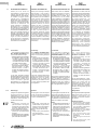 4
4
-
 5
5
-
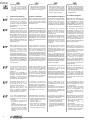 6
6
-
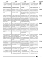 7
7
-
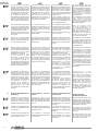 8
8
-
 9
9
-
 10
10
-
 11
11
-
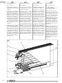 12
12
-
 13
13
-
 14
14
-
 15
15
-
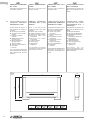 16
16
-
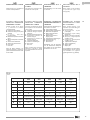 17
17
-
 18
18
-
 19
19
-
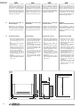 20
20
-
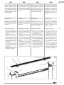 21
21
-
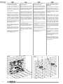 22
22
-
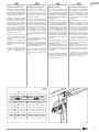 23
23
-
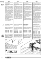 24
24
-
 25
25
-
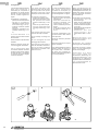 26
26
-
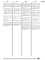 27
27
-
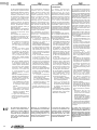 28
28
-
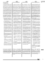 29
29
-
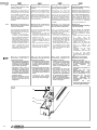 30
30
-
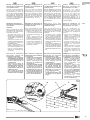 31
31
-
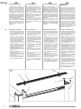 32
32
-
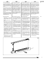 33
33
-
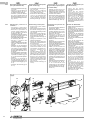 34
34
-
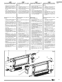 35
35
-
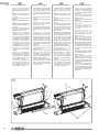 36
36
-
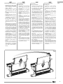 37
37
-
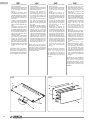 38
38
-
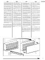 39
39
-
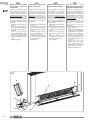 40
40
-
 41
41
-
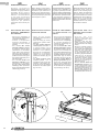 42
42
-
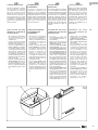 43
43
-
 44
44
-
 45
45
-
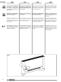 46
46
-
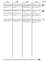 47
47
-
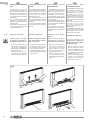 48
48
-
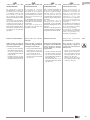 49
49
-
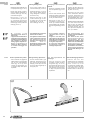 50
50
-
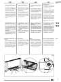 51
51
-
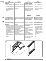 52
52
-
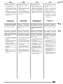 53
53
-
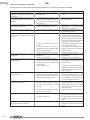 54
54
-
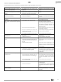 55
55
-
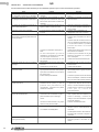 56
56
-
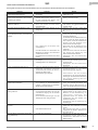 57
57
-
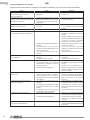 58
58
-
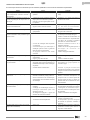 59
59
-
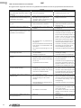 60
60
-
 61
61
-
 62
62
-
 63
63
-
 64
64


Olimpia Splendid Bi2 SL inverter Guida d'installazione
- Categoria
- Bilance da cucina
- Tipo
- Guida d'installazione
- Questo manuale è adatto anche per
in altre lingue
- English: Olimpia Splendid Bi2 SL inverter Installation guide
- français: Olimpia Splendid Bi2 SL inverter Guide d'installation
- español: Olimpia Splendid Bi2 SL inverter Guía de instalación
- Deutsch: Olimpia Splendid Bi2 SL inverter Installationsanleitung
- Nederlands: Olimpia Splendid Bi2 SL inverter Installatie gids
- português: Olimpia Splendid Bi2 SL inverter Guia de instalação
Documenti correlati
-
 Olimpia Splendid Bi2 Nano Guida d'installazione
-
 Olimpia Splendid Bi2 Wall Inverter Guida d'installazione
-
 Olimpia Splendid Bi2 SL Air Inverter Manuale utente
-
 Olimpia Splendid Bi2 SLR smart inverter Guida d'installazione
-
 Olimpia Splendid Bi2 SLI inverter naked Guida d'installazione
-
 Olimpia Splendid Bi2 SLIR inverter naked ultraslim Guida d'installazione
-
 Olimpia Splendid Bi2 Series Manuale utente
-
 Olimpia Splendid Condensate collection tray Kit B0520-B0521-B0522-B0523-B0524 Manuale utente
-
Olimpia Splendid Bi2 Wall TR Manuale utente
-
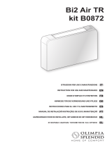 Olimpia Splendid Bi2 SLR Air Inverter Slim Manuale utente


Altri documenti
-
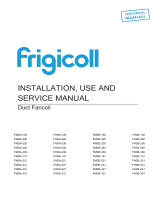 Kaysun Ducts medium/high pressure Manuale utente
-
ROSIERES CEN 126 IN Manuale del proprietario
-
Vasco FC115 Niva Fan Coil Unit Manuale utente
-
aerauliqa Quantum HR Serie Guida d'installazione
-
Bosch Appliances UHI-SBG-0 Manuale utente
-
aerauliqa Quantum HR Istruzioni per l'uso
-
iNOXPA SLR Manuale utente
-
Innova SLF 400 Manuale utente
-
LU-VE FHA Commercial Angled Glycol Air Coolers Manuale utente
-
Rittal Top Therm SK 3129.1 Series Assembly Instructions Manual
