ZANKER ZNP62HIBK Manuale utente
- Categoria
- Piani cottura
- Tipo
- Manuale utente

Libretto istruzioni per l'installazione e l'uso
di PIANI DI COTTURA IN VETROCERAMICA
Notice d'installation et d'utilisation de
TABLES DE CUISSON VITROCERAMIQUES
Instructions for use and maintenance of
CERAMIC HOBS
Installations- und Bedienungsanleitung für
GLASKERAMIK-KOCHFLÄCHEN
Handleiding voor installatie en gebruik van
GLASKERAMISCHE KOOKPLATEN
Posobie po ustanovke i ispol;zovani[Posobie po ustanovke i ispol;zovani[
Posobie po ustanovke i ispol;zovani[Posobie po ustanovke i ispol;zovani[
Posobie po ustanovke i ispol;zovani[
KUXONNYX PLIT IZ STEKLOKERAMIKIKUXONNYX PLIT IZ STEKLOKERAMIKI
KUXONNYX PLIT IZ STEKLOKERAMIKIKUXONNYX PLIT IZ STEKLOKERAMIKI
KUXONNYX PLIT IZ STEKLOKERAMIKI
Manual de instruções para a instalação e
uso de PLACAS DE COZEDURA COM
VIDRO CERÂMICO
∂Á¯ÂÈÚ›‰ÈÔ Ô‰ËÁÈÒÓ ÁÈ· ÙËÓ ÂÁηٿÛÙ·ÛË Î·È∂Á¯ÂÈÚ›‰ÈÔ Ô‰ËÁÈÒÓ ÁÈ· ÙËÓ ÂÁηٿÛÙ·ÛË Î·È
∂Á¯ÂÈÚ›‰ÈÔ Ô‰ËÁÈÒÓ ÁÈ· ÙËÓ ÂÁηٿÛÙ·ÛË Î·È∂Á¯ÂÈÚ›‰ÈÔ Ô‰ËÁÈÒÓ ÁÈ· ÙËÓ ÂÁηٿÛÙ·ÛË Î·È
∂Á¯ÂÈÚ›‰ÈÔ Ô‰ËÁÈÒÓ ÁÈ· ÙËÓ ÂÁηٿÛÙ·ÛË Î·È
ÙË ¯Ú‹ÛË ÙÔ˘ ¶§A∆øÙË ¯Ú‹ÛË ÙÔ˘ ¶§A∆ø
ÙË ¯Ú‹ÛË ÙÔ˘ ¶§A∆øÙË ¯Ú‹ÛË ÙÔ˘ ¶§A∆ø
ÙË ¯Ú‹ÛË ÙÔ˘ ¶§A∆ø
∫∂ƒ∞ªπ∫ø¡ E™TIøN∫∂ƒ∞ªπ∫ø¡ E™TIøN
∫∂ƒ∞ªπ∫ø¡ E™TIøN∫∂ƒ∞ªπ∫ø¡ E™TIøN
∫∂ƒ∞ªπ∫ø¡ E™TIøN
IT
FR
GB
DE
NL
RU
PT
GR

12
Index
GB Introduction
Technical data and
specifications............................. 13
Installation .......................... 13 - 14
Positioning..................................... 13
Fixing............................................. 13
Electrical connection ..................... 14
For the user ........................ 15 - 16
Using the ceramic hob .................. 15
Cleaning the ceramic hob ............. 15
Advice and precautions ................. 16
Figures ............................... 45 - 47
- Thank you for choosing one of our quality
products, capable of giving you the very
best service. To make full use of its perfor-
mance features, read the parts of this
manual which refer to your appliance
carefully. The Manufacturer declines all
responsibility for injury or damage
caused by poor installation or improper
use of the appliance.
- To ensure its appliances are always at the
state of the art, and/or to allow constant
improvement in quality, the manufacturer
reserves the right to make modifications
without notice, although without creating
difficulties for users.
- If spare parts are required, your order to
your dealer must include the model number
and serial number indicated on the
nameplate underneath the hob.
- APPLIANCE COMPLYING WITH THE
FOLLOWING DIRECTIVES:
- EEC 73/23 and 93/88
- EEC 89/336 (radio-frequency inter-
ference)
- EEC 89/109 (contact with foods)
FOREWORD
- Refer only to the headings and sections
covering accessories actually installed on
your appliance.

13
Technical data
GB
Installation
ELECTRIC HOTPLATES
ø 145 mm 1,2 kW - Normal hotplate
1,2 kW - Halogen hotplate
ø 180 mm 1,8 kW - Normal hotplate
1,8 kW - Halogen hotplate
Type “X” hobs
EQUIPMENT
Depending on the models, hobs may have:
- One or more halogen hotplates
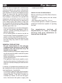
For the LAYOUT OF THE HOTPLATES ON
THE HOB see figure 1 at the back of this
manual.
For the ELECTRIC WIRING DIAGRAM see
figure 2 at the back of this manual.
The electrical power is stated on the name-
plate underneath the hob.
A copy of the nameplate is glued to the cover
of this manual.
INSTALLATION
The appliance must be installed by qualified
staff working in accordance with the regula-
tions in force.
You are advised to read these instructions
for use carefully; they contain important in-
formation which ensures the safety of the
installation. Keep these instructions in a safe
place.
After removing the packaging, ensure that
the appliance is not damaged:
- in particular, the ceramic glass hob must
not be broken or cracked;
Keep all the parts of the packaging (plastic
bags, polystyrene etc.) out of reach of chil-
dren, since they are a source of potential
danger.
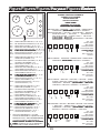
POSITIONING (fig. 3)
Place the hob well away from items of furni-
ture taller than the hob for built-in installa-
tion. Any partition parallel to the hob must
be at least 1 cm lower than the box unit in
which it is installed, and a square opening
with sides of 10 cm must be made under the
outlet of the power supply cable.
The ceramic hob can be inserted in all kind
of table tops (brickwork, metal, wood) pro-
viding they resist to a temperature of 120°
C. The sizes of the hole to be cut in the
worktop can be seen in figure 3.
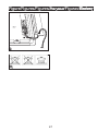
FIXING
A self-adhesive seal (A) is supplied with the
hob. This must be placed under the edge of
the box unit, as close as possible to the edge
itself (fig. 4). The seal must run all round the
unit to ensure a perfect seal and prevent
moisture from seeping under the hob.
Fit the spring nuts (B) into the holes in the
box unit (fig. 4).
Place the hob in the hole in the work top,
making sure that the adhesive ensures a
good seal between the edge of the hob and
the surface of the supporting unit (fig. 5) and
conclude fixing by tightening the screws
which secure the hooks (C) into their seats

14
(fig. 6). If there is a 4 cm worktop, the hooks
should be placed as shown in figure 7a, that
is with the long part into the opening. Other-
wise, if there is a 3 cm worktop, the hooks
should be placed as shown in figure 7b, that
is with the short part into the hole.
IMPORTANT: Perishable things should
not be put below the hob.
CONNECTING TO THE ELECTRICAL
MAINS
The connection to the mains electrical sup-
ply must be made by a professional electri-
cian, who must take care to observe the nec-
essary precautions.
Before making the connection, check that:
- the mains voltage is as indicated on the
nameplate;
- the electrical line to which the appliance is
connected is of rated power appropriate to
the maximum power absorption of the ap-
pliance, indicated on its nameplate;
- the earth connection is in good working or-
der.
If the socket is not easily accessible, the in-
stallation engineer must provide an
omnipolar switch with a contact breaking gap
of 3 mm or more.
- If the appliance is supplied without lead,
using type H05RR-F or H05V2V2-F cable
of suitable size (see diagrams in fig. 2).
- Calibre of the protection device: 30A.
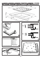
To connect the hob to the electrical mains:
- remove the controls protection cover on the
underside of the hob by unscrewing the 3
screws (see fig. 8);
- connect the power supply lead to the ter-
minal board, following the diagrams of fig-
ure 2;
- fix the cable with a cable clamp (see fig. 9);
- replace the protection cover.
IMPORTANT: the manufacturer declines all
liability for damage due to failure to comply
with the regulations and standards in force.
Check that the appliance is correctly con-
nected to the earth (see diagrams in fig. 2 at
the back of the manual).
CAUTION
- Before doing any work inside the hob, dis-
connect the mains plug.
GB Installation

15
HOW TO USE THE HOB
HOW TO USE THE CERAMIC HOB
Hobs can be equipped with two different
kinds of plates:
- halogen plates that allow an immediate
visualization and an almost immediate heat-
ing
- radiant plates
The hotplate power has a sequential control
device which ensures excellent control of the
cooking temperature.
The heat settings are from 1 to 6. The knob
can be set in the required position by turning
it to right or left.
When the knob of one of the cooking zones
is turned, the corresponding warning light of
the unit E (see fig. 1) comes on; it will not go
off until the temperature of the hotplate in
question has dropped below about 60 de-
grees C).
The four cooking zones are indicated by the
outlines screen-printed on the hob. For good
efficiency and appropriate energy consump-
tion, only use saucepans and utensils with
thick, perfectly flat bottoms (see fig. 10). The
diameter of the base of the pan must be at
least as large as the outline marked on the
hob. If the bottom of the pan does not cover
the heating area, energy will be wasted. Pref-
erably, it should be slightly larger in diam-
eter.
Pan bottoms and the cooking surface must
be clean and dry. Otherwise heat, and thus
energy, will be wasted.
Note:
- Never cook directly on the hotplates.
- The halogen plates become warm almost
immediately. This quickness in heating can
be exploited for rapid cookings (ex. steaks)
and to heat small quantity of liquids.
- To save time, cooking with the radiant or
halogen hotplates may be started at full
heat (knob on 6), turning down to the ideal
temperature once the contents of the pan
have heated up.
- All the hotplates are equipped with a tem-
perature limiter which prevents them from
overheating, even if a hotplate is operated
at the highest setting with no pan, or if pans
with uneven bottoms are used.
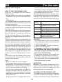
The table below will serve as a guide, bear-
ing in mind that cooking times and tempera-
tures may vary depending on the type and
amount of foods cooked and personal taste.
Knob Cooking process
setting
1 - 2 Keeping foods warm,
bechamel sauce, custard
2 - 3 Reheating foods
3 - 4 Pasta, vegetable soups,
ragout, keeping water boiling
4 - 5 Roasting, fish
5 - 6 Steamed vegetables, steaks
6 Grilling, omelettes, lamb
chops, boiling water
CAUTION
- The ceramic glass surface is very tough but
it is not shatterproof and it may not be used
to place objects upon it.
- It may be damaged if struck violently by
sharp or very hard objects.
- If breakages, crazing or cracks appear
on its surface, stop using it, disconnect
the power supply and contact the after-
sales service immediately.
- Do not place aluminium foil or plastic film
wrappings on the hob while it is still hot.
- Soon after installation, the hob may give
off a burnt smell; this will disappear after
the first few times it is used.
IMPORTANT
Because of their height, children may fail to
see the residual heat warning light. Take care
that they do not touch the hob, even if the
heating elements are switched off.
CLEANING OF THE CERAMIC HOB
The ceramic hob is much easier to clean than
a hob with conventional hotplates. Light dirt
can be removed with a sheet of damp kitchen
For the user
GB

16
paper. To remove tougher dirt, use the same
cleaning methods as for glass, with specific
detergents. If a pan boils over onto the hob,
use a spatula to remove the deposit formed.
Sugar or syrup must be removed immedi-
ately before it forms caramel on the glass.
Any residues of aluminium foil or plastic film
wrappings accidentally placed on the hob
while it is still hot must also be removed at
once. Water marks and traces of scale can
be removed with white wine vinegar. Always
remember to rinse and dry the surface with
kitchen paper after use.
- Never use abrasive or corrosive detergents,
such as oven sprays, degreasers, rust-re-
movers, powder polishing detergents or
abrasive sponges.
- Do not allow grains of sand to be left on
the hob when cleaning vegetables, for ex-
ample, as they may scratch the surface.
- Do not slide pans with rough bottoms over
the hob; they may mark or even scratch
the glass.
GENERAL PRECAUTIONS
- Do not look directly at the halogen
hotplates while they are on, as the light
emitted from the hotplates may be
harmful to your eyes.
- Always disconnect the power supply before
any work inside the hob or where live parts
may be accessed.
- Never use abrasives to clean enamelled or
chrome-plated parts.
- This appliance may only be used for cook-
ing. Any other use (e.g. heating rooms, etc.)
must be considered improper and thus haz-
ardous.
A number of fundamental precautions must
be complied with when using household elec-
trical appliances. In particular:
- The ceramic-glass hob has good mechani-
cal strength and thus withstands small ac-
cidental knocks. If the hob is broken or
cracked by a knock, do not use the appli-
ance, disconnect the power supply and
For the user
GB
contact your dealer.
Advice in case of malfunctions
Before contacting your After-Sales Service,
check that:
- the plug is fitted properly into the mains
socket;
- the master pilot (see E fig. 1) is on.
If the problem persists, consult a qualified,
authorised technician capable of repairing
the fault.
The manufacturer declines all
responsibility for injury or damage
deriving from poor installation or
incorrect use of the hob.

45
1 3 4 52
L
N
1 3 4 52
LLL
LN
L
L
1 3 4 52
2
1 3 4 52
N
Ø 145
A
Ø 180
B
Ø 180
C
Ø 145
D
E
1
L
L
MOD. 4 PIASTRE ELETTRICHE (= A, B, C, D)
MOD. 4 PLAQUES ÉLECTRIQUES (= A, B, C, D)
MOD. 4 ELECTRIC PLATES (= A, B, C, D)
MOD. 4 ELEKTRO-KOCHZONEN (= A, B, C, D)
MOD. 4 ELEKTRISCHE PLAATJES (= A, B, C, D)
MOD.MOD.
MOD.MOD.
MOD.
4 ~LEKTRIHESKIE KONFORKI (/ 4 ~LEKTRIHESKIE KONFORKI (/
4 ~LEKTRIHESKIE KONFORKI (/ 4 ~LEKTRIHESKIE KONFORKI (/
4 ~LEKTRIHESKIE KONFORKI (/ A, B, C, D
))
))
)
MOD. 4 DISCOS ELÉCTRICOS (= A, B, C, D)
MO¡∆. 4 ∏§∂∫∆ƒπ∫∂™ ∂™∆π∂™ (= A, B, C, D)
MOD. 3 PIASTRE ELETTRICHE (= A, B, C) +
1 PIASTRA ALOGENA (= D)
MOD. 3 PLAQUES ÉLECTRIQUES (= A, B, C) +
1 PLAQUE HALOGÈNE (= D)
MOD. 3 ELECTRIC PLATES (= A, B, C) +
1 HALOGEN PLATE (= D)
MOD. 3 ELEKTRO-KOCHZONEN (= A, B, C) +
1 HALOGEN-KOCHZONE (= D)
MOD. 3 ELEKTRISCHE PLAATJES (= A, B, C) +
1 HALOGEEN PLAATJE (= D)
MOD.MOD.
MOD.MOD.
MOD.
3 ~LEKTRIHESKIE KONFORKI (/3 ~LEKTRIHESKIE KONFORKI (/
3 ~LEKTRIHESKIE KONFORKI (/3 ~LEKTRIHESKIE KONFORKI (/
3 ~LEKTRIHESKIE KONFORKI (/A, B, C
) )
) )
) +
1 1
1 1
1
GALOGENNAQ KONFORKA GALOGENNAQ KONFORKA
GALOGENNAQ KONFORKA GALOGENNAQ KONFORKA
GALOGENNAQ KONFORKA
(/ (/
(/ (/
(/ D
))
))
)
MOD. 3 DISCOS ELÉCTRICOS (= A, B, C) +
1 DISCO HALÓGENO (= D)
MO¡∆. 3 ∏§∂∫∆ƒπ∫∂™ ∂™∆π∂™ (= A, B, C) +
1 A§√°√¡A ∂™∆πA (= D)
MOD. 2 PIASTRE ELETTRICHE (= A, B) +
2 PIASTRE ALOGENE (= C, D)
MOD. 2 PLAQUES ÉLECTRIQUES (= A, B) +
2 PLAQUES HALOGÈNES (= C, D)
MOD. 2 ELECTRIC PLATES (= A, B) +
2 HALOGEN PLATES (= C, D)
MOD. 2 ELEKTRO-KOCHZONEN (= A, B) +
2 HALOGEN-KOCHZONEN (= C, D)
MOD. 2 ELEKTRISCHE PLAATJES (= A, B) +
2 HALOGENE PLAATJES (= C, D)
MOD.MOD.
MOD.MOD.
MOD.
2 ~LEKTRIHESKIE KONFORKI (/2 ~LEKTRIHESKIE KONFORKI (/
2 ~LEKTRIHESKIE KONFORKI (/2 ~LEKTRIHESKIE KONFORKI (/
2 ~LEKTRIHESKIE KONFORKI (/A, B
) )
) )
) +
2 2
2 2
2
GALOGENNYE KONFORKI GALOGENNYE KONFORKI
GALOGENNYE KONFORKI GALOGENNYE KONFORKI
GALOGENNYE KONFORKI
(/ (/
(/ (/
(/ C, D
))
))
)
MOD. 2 DISCOS ELÉCTRICOS (= A, B) +
2 DISCOS HALÓGENOS (= C, D)
MO¡∆. 2 ∏§∂∫∆ƒπ∫∂™ ∂™∆π∂™ (= A, B) +
2 A§√°√¡∂™ ∂™∆π∂™ (= C, D)
E = SPIA CALORE RESIDUO / VOYANT
CHALEUR RESIDUELLE / RESIDUAL HEAT
WARNING LIGHT / RESTWÄRMEANZEIGE /
CONTROLELAMPJE RESTWARMTE /
INDIKATORNAQ LAMPOHKA OSTATOHNOGOINDIKATORNAQ LAMPOHKA OSTATOHNOGO
INDIKATORNAQ LAMPOHKA OSTATOHNOGOINDIKATORNAQ LAMPOHKA OSTATOHNOGO
INDIKATORNAQ LAMPOHKA OSTATOHNOGO
TEPLATEPLA
TEPLATEPLA
TEPLA/ LÂMPADA DE CALOR RESIDUAL /
∂¡¢∂π∫∆π∫∏ §ÀáπA £∂ƒªO∆∏∆A™
SCHEMA DI COLLEGAMENTO
SCHEMA DES BRANCHEMENTS
CONNECTION DIAGRAM
ANSCHLUSSPLAN
AANSLUITSCHEMA
SXEMA SVQZISXEMA SVQZI
SXEMA SVQZISXEMA SVQZI
SXEMA SVQZI
ESQUEMA DE LIGAÇÃO
∏§∂∫∆ƒπ∫√ ¢π∞°ƒ∞ªª∞∏§∂∫∆ƒπ∫√ ¢π∞°ƒ∞ªª∞
∏§∂∫∆ƒπ∫√ ¢π∞°ƒ∞ªª∞∏§∂∫∆ƒπ∫√ ¢π∞°ƒ∞ªª∞
∏§∂∫∆ƒπ∫√ ¢π∞°ƒ∞ªª∞
230 V BIFASE / BIPHASE / TWO-PHASE / ZWEIPHASIG /
TWEEFASIG /
DVUXFAZNYJDVUXFAZNYJ
DVUXFAZNYJDVUXFAZNYJ
DVUXFAZNYJ/ BIFÁSICO / ¢πº∞™π∫√
400 V MONOFASE + NEUTRO / MONOPHASE + NEUTRE /
SINGLE-PHASE + NEUTRAL / EINPHASIG +
NEUTRALLEITER / ENKELFASIG + NEURAAL /
ODNOFAZNYJ ODNOFAZNYJ
ODNOFAZNYJ ODNOFAZNYJ
ODNOFAZNYJ +
NEJTRAL: NEJTRAL:
NEJTRAL: NEJTRAL:
NEJTRAL: / MONOFÁSICO + NEUTRO /
MONOº∞™π∫√ + √À¢∂∆∂ƒ√
Sez. cavo
Section câble
Wire gauge
Leiterquerschnitt
Doorsneede kabel
Sehenie kabelqSehenie kabelq
Sehenie kabelqSehenie kabelq
Sehenie kabelq
Sec. cabo
¢È·Ù. ηÏÒ‰ÈÔ˘:
3x4 mm
2
230 V TRIFASE / TRIPHASE / THREE-PHASE / DREIPHASIG /
DRIEFASIG /
TR|XFAZNYJTR|XFAZNYJ
TR|XFAZNYJTR|XFAZNYJ
TR|XFAZNYJ/ TRIFÁSICO / ∆ƒπº∞™π∫√
Sez. cavo
Section câble
Wire gauge
Leiterquerschnitt
Doorsneede kabel
Sehenie kabelqSehenie kabelq
Sehenie kabelqSehenie kabelq
Sehenie kabelq
Sec. cabo
¢È·Ù. ηÏÒ‰ÈÔ˘:
4x2,5 mm
2
400 V TRIFASE + NEUTRO / TRIPHASE + NEUTRE / THREE-
PHASE + NEUTRAL / DREIPHASIG + NEUTRALLEITER /
DRIEFASIG + NEURAAL /
DVUXFAZNYJ DVUXFAZNYJ
DVUXFAZNYJ DVUXFAZNYJ
DVUXFAZNYJ +
NEJTRAL: NEJTRAL:
NEJTRAL: NEJTRAL:
NEJTRAL:/
TRIFÁSICO + NEUTRO / ∆ƒπº∞™π∫√ + √À¢∂∆∂ƒ√
Sez. cavo
Section câble
Wire gauge
Leiterquerschnitt
Doorsneede kabel
Sehenie kabelqSehenie kabelq
Sehenie kabelqSehenie kabelq
Sehenie kabelq
Sec. cabo
¢È·Ù. ηÏÒ‰ÈÔ˘:
5x1,5 mm
2
400 V BIFASE + NEUTRO / BIPHASE + NEUTRE / TWO-PHASE
+ NEUTRAL / ZWEIPHASIG + NEUTRALLEITER /
TWEEFASIG + NEURAAL /
DVUXFAZNYJ DVUXFAZNYJ
DVUXFAZNYJ DVUXFAZNYJ
DVUXFAZNYJ +
NEJTRAL: NEJTRAL:
NEJTRAL: NEJTRAL:
NEJTRAL:/
BIFÁSICO + NEUTRO / ¢πº∞™π∫√ + √À¢∂∆∂ƒ√
Sez. cavo
Section câble
Wire gauge
Leiterquerschnitt
Doorsneede kabel
Sehenie kabelqSehenie kabelq
Sehenie kabelqSehenie kabelq
Sehenie kabelq
Sec. cabo
¢È·Ù. ηÏÒ‰ÈÔ˘:
4x2,5 mm
2
Figure/Figures/Figures/
RisunkiRisunki
RisunkiRisunki
Risunki
/Figuras/
∂ÈÎfiÓ˜∂ÈÎfiÓ˜
∂ÈÎfiÓ˜∂ÈÎfiÓ˜
∂ÈÎfiÓ˜

46
3
510
5
8
0
490
560
100
C
6
4
A
5
B
a
7
8
A
4 cm
3 cm
b
Figure/Figures/Figures/
RisunkiRisunki
RisunkiRisunki
Risunki
/Figuras/
∂ÈÎfiÓ˜∂ÈÎfiÓ˜
∂ÈÎfiÓ˜∂ÈÎfiÓ˜
∂ÈÎfiÓ˜

47
9
10
Figure/Figures/Figures/
RisunkiRisunki
RisunkiRisunki
Risunki
/Figuras/
∂ÈÎfiÓ˜∂ÈÎfiÓ˜
∂ÈÎfiÓ˜∂ÈÎfiÓ˜
∂ÈÎfiÓ˜

ED. 13.11.1998 334739/02B1/48
-
 1
1
-
 2
2
-
 3
3
-
 4
4
-
 5
5
-
 6
6
-
 7
7
-
 8
8
-
 9
9
-
 10
10


ZANKER ZNP62HIBK Manuale utente
- Categoria
- Piani cottura
- Tipo
- Manuale utente
in altre lingue
- English: ZANKER ZNP62HIBK User manual