ProLights ARCPOD27Q Manuale utente
- Categoria
- Stroboscopi
- Tipo
- Manuale utente

USER MANUAL
MANUALE UTENTE
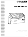
ARCPOD27Q
OUTDOOR COMPACT WASHLIGHT
EN - IT

All rights reserved by Music & Lights S.r.l. No part of this instruction manual may be
reproduced in any form or by any means for any commercial use.
In order to improve the quality of products, Music&Lights S.r.l. reserves the right to modify the characteris-
tics stated in this instruction manual at any time and without prior notice.
All revisions and updates are available in the ‘manuals’ section on site www.musiclights.it
REV. 03-11/19

1
ARCPOD27Q
Packing content
• ARCPOD27Q
• Power adaptor cable
• Signal adaptor cable (2 pcs)
• User manual
TABLE OF CONTENTS
Safety
General instructionsGeneral instructions
Warnings and installation precautionsWarnings and installation precautions
1 Introduction
1. 1 Description 1. 1 Description
1. 2 Technical specications1. 2 Technical specications
1. 3 Operating elements and connections1. 3 Operating elements and connections
2 Installation
2. 1 Mounting2. 1 Mounting
3 Functions and settings
3. 1 Operation3. 1 Operation
3. 2 Basic3. 2 Basic
3. 3 RDM mode3. 3 RDM mode
3. 4 RDM function3. 4 RDM function
3. 5 Linking3. 5 Linking
3. 6 DMX addressing conguration3. 6 DMX addressing conguration
3. 7 DMX mode conguration3. 7 DMX mode conguration
3. 8 DMX addressing3. 8 DMX addressing
3. 9 LED frequency 3. 9 LED frequency
3. 10 Sensor menu3. 10 Sensor menu
3. 11 Sw version3. 11 Sw version
3. 12 UID3. 12 UID
3. 13 Factory Default 3. 13 Factory Default
3. 14 Manual color3. 14 Manual color
3. 15 Eects3. 15 Eects
3. 16 Connection of the DMX line3. 16 Connection of the DMX line
3. 17 Construction of the DMX termination 3. 17 Construction of the DMX termination
3. 18 DMX control 3. 18 DMX control
4 Maintenance
4. 1 Maintenance and cleaning the unit4. 1 Maintenance and cleaning the unit
4. 2 Trouble shooting4. 2 Trouble shooting
2
2
3
3
5
6
7
7
8
8
9
9
9
9
10
10
10
10
11
11
11
12
12
13
16
16

ARCPOD27Q
2
WARNING! Before carrying out any operations with the unit, carefully read this instruction
manual and keep it with cure for future reference. It contains important information about
the installation, usage and maintenance of the unit.
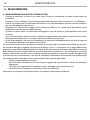
SAFETY
General instruction
• The products referred to in this manual conform to the European Community Directives and are there-
fore marked with .
• The unit is supplied with hazardous network voltage (230V~). Leave servicing to skilled personnel only.
Never make any modications on the unit not described in this instruction manual, otherwise you will
risk an electric shock.
• Connection must be made to a power supply system tted with ecient earthing (Class I appliance ac-
cording to standard EN 60598-1). It is, moreover, recommended to protect the supply lines of the units
from indirect contact and/or shorting to earth by using appropriately sized residual current devices.
• The connection to the main network of electric distribution must be carried out by a qualied electrical
installer. Check that the main frequency and voltage correspond to those for which the unit is designed
as given on the electrical data label.
• This unit is not for home use, only professional applications.
• Never use the xture under the following conditions:
- in places subject to vibrations or bumps;
- in places with an ambient temperature of over 50°C.
• Make certain that no inammable liquids, water or metal objects enter the xture.
• Do not dismantle or modify the xture.
• All work must always be carried out by qualied technical personnel. Contact the nearest sales point for
an inspection or contact the manufacturer directly.
• If the unit is to be put out of operation denitively, take it to a local recycling
plant for a disposal which is not harmful to the environment.
Warnings and installation precautions
• If this device will be operated in any way dierent to the one described in this manual, it may suer
damage and the guarantee becomes void. Furthermore, any other operation may lead to dangers like
short circuit, burns, electric shock, etc.
• Before starting any maintenance work or cleaning the projector, cut o power from the main supply.
• When carrying out any work, always comply scrupulously with all the regulations (particularly regard-
ing safety) currently in force in the country in which the xture’s being used.
• The minimum distance between the xture and surrounding walls must be more than 50 cm and the
air vents at the housing must not be covered in any case.
• Keep any inammable material at a safe distance from the xture.
• The maximum temperature that can be reached on the external surface of the tting, in a thermally
steady state, is high. After power o, please cool down over 15 minutes.
• Shields, lenses or ultraviolet screens shall be changed if they have become damaged to such an extent
that their eectiveness is impaired.
• The lamp (LED) shall be changed if it has become damaged or thermally deformed.
• Never look directly at the light beam. Please note that fast changes in lighting, e. g. ashing light, may
trigger epileptic seizures in photosensitive persons or persons with epilepsy.
• This product was designed and built strictly for the use indicated in this documentation. Any other use,
not expressly indicated here, could compromise the good condition/operation of the product and/or
be a source of danger. We decline any liability deriving from improper use of the product

3
ARCPOD27Q
- 1 - INTRODUCTION
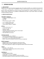
1.1 DESCRIPTION
ARCPOD27Q is a compact high-power outdoor wash light featuring an outstanding brightness of 11'480
lumens. Equipped with 27x10W RGBW / FC LEDs, delivering superior colour mixing. The slim sizing, as
well as the wide range of available optics through the magnet, makes the ARCPOD27Q an incredibly
exible and versatile device for large outdoor applications.
1.2 TECHNICAL SPECIFICATIONS
LIGHT SOURCE
• Source: 27x10W RGBW / FC LEDs
• CRI: 71,8
• Luminous ux: @full 11'480lm
• Lux: 15° @full 11'276lx @3 m
• Lux: 15° @full 4'060lx @5 m
• Source life expectancy: > 50.000 h
OPTICS
• Beam angle: 15°
• Field angle: 28°
• Additional optics: 10° - 25° - 45°
• Other: barn doors not included
COLOUR SYSTEM
• Colour mixing: RGBW / FC
• CTC: CTC control through independent DMX channel
• Colour wheel: virtual colour wheel with presets
• Macros: several pre-build macros with adjustable speed
DYNAMIC EFFECTS
• FX generator: section eect with 3 horizontal individually select and control sections
• Static colour mode: selection of static colour
• Manual colour mode: manual adjustment of colour
• Auto mode: built-in programs with execution speed adjustment
BODY
• Tilt angle: 0 - 130° manual
• Body: sturdy die-cast aluminium body conceived for long-time durability
• Body colour: grey
CONTROL
• Protocols: DMX512, RDM
• DMX channels: 5 / 7 / 10 / 13 / 17channel
• RDM: RDM ready for xture remote monitor and settings
• Display: user interface through DATAMASTER external coder (not included)
• Firmware upgrade: yes, via USB - DMX interface (UPBOX1) not included
• Master/Slave: for synchronized operation of more units linked in a chain

ARCPOD27Q
4
ELECTRONICS
• Dimmer: linear 0 ~ 100% electronic dimmer
• Operating temperature: -20° ~ +50°
• Flicker: icker free operation
• Selectable PWM: 600 ~ 25.000 Hz
ELECTRICAL
• Power supply: 100-240 V – 50/60 Hz
• Power consumption (at 230 V): 268W
• Power consumption (at 120 V): 275W
• Output (at 230 V): 9 units on a single power line
• Output (at 120 V): 5 units on a single power line
• Power factor: 0,994
PHYSICAL
• Cooling: natural cooling of the peculiar chassis and to absence of fans
• Adaptors: XLR and Shuko 16A adaptors included
• Signal connection: moulded IP signal IN/OUT connectors
• Power connection: moulded IP signal IN/OUT connectors
• IP rating: 66 for outdoor installations
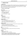
• Dimensions (WxHxD): 454x269x83mm
• Weight: 9kg
258mm/10.15in
455mm/17.91in
83mm/
3.26in
Technical drawing Fig.1

5
ARCPOD27Q
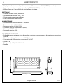
2
3
1
4 5 6 7
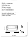
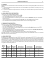
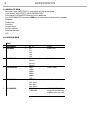
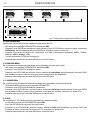
1.3 OPERATING ELEMENTS AND CONNECTIONS
1. LED panel
2. MECHANICAL SYSTEM for individual positioning of Led panels
3. POWER SUPPLY CASING SET
4. POWER IN: for connection to a socket (100-240V~/50-60Hz) via the
supplied mains cable
5. DMX IN DMX IN (5-pole XLR): 1 = ground, 2 = DMX-, 3 = DMX+, 4
N/C, 5 N/C.
6. DMX OUT DMX OUT (5-pole XLR): 1 = ground, 2 = DMX-, 3 = DMX+,
4 N/C, 5 N/C.
7. POWER OUT: connect to supply power to the next unit.
Fig.2

ARCPOD27Q
6
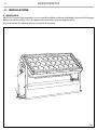
- 2 - INSTALLATION
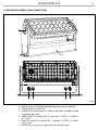
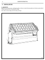
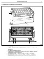
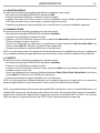
2.1 MOUNTING
ARCPOD27Q can be set on a solid and uniform surface using the fastening devices of the base plate (g.3).
Stable mounting clips are required for xing.
Also make sure to comply with all safety warnings.
Fig.3
1
2

7
ARCPOD27Q
- 3 - FUNCTIONS AND SETTINGS
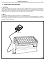
3.1 OPERATION
Connect the supplied main cable to a socket (100-240V~/50-60Hz). The unit will run built-in program to
reset all motors to their home position. Shortly after that the ARCPOD27Q is ready for operation. To switch
o, disconnect the mains plug from the socket. For a more convenient operation it is recommended to
connect the unit to a socket which can be switched on and o via light switch.
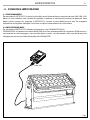
3.2 BASIC
To control the ARCPOD27Q connect the device to a DATAMASTER (g.4).
DATAMASTER is a powerful RDM-DMX tool that automatically detects connected RDM devices, allowing
direct and fast monitoring and control. Information on the status of the connected xture can be read
from the DATAMASTER display.
DMX OUT
Fig.4

ARCPOD27Q
8
3.3 RDM MODE
To use the ARCPOD27Q proceed as follows:
• Connect the ARCPOD27Q to a DATAMASTER.
• Turn on the DATAMASTER using the dedicated button.
• With the DATAMASTER select RDM to show the following info about:
• Model;
• Manufacturer;
• Function;
• Temperature;
• Factory Default;
• Software Version;
• UID.
3.4 MENU STRUCTURE
MENU
1 DMX ADDRESS
ð
001-512 Default: 1
2 DMX MODE
ð
5CH
7CH
10CH
13CH
17CH
Default: 10CH
3 DIMMER MODE
ð
O
Dimmer1
Dimmer2
Dimmer3
Default: O
4 LED FREQUENCY
ð
600Hz
1200Hz
2000Hz
4000Hz
6000Hz
25kHz
Default: 1200Hz
5 SPECIFIC PIDS
ð
8200 (RED)
8201 (Green)
8202 (Blue)
8203 (White)
White Balance
6 FULL ON MODE
ð
HB MODE
STUDIO MODE
HB MODE (STUDIO MODE is
auto balance mode at 6000K
for colors at full)

9
ARCPOD27Q
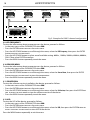
3.5 LINKING
Multiple units can be connected so that all secondary units have the same lighting eect as the main unit
(Master).
1. 1. Connect the DMX OUT output of the main unit to the DMX IN input of the rst secondary unit using
5 pole XLR cable.
2. 2. Connect the DMX OUT output of the rst secondary unit with the DMX IN input of the second sec-
ondary unit, etc.
3.6 DMX ADDRESSING CONFIGURATION
To enter the DMX mode proceed as follows:
• In the main menu of the DATAMASTER select RDM.
• Press the ENTER button to access the main menu.
• Press the UP/DOWN button to scroll through the menu, select the Start Addrees, then press the ENTER
button to access.
• Use the arrow buttons to set the desired value (001-512). Press the ENTER button to conrm.
• Press the MENU button repeatedly to exit the menu and to save the changes made.
3.7 DMX MODE CONFIGURATION
ARCPOD27Q has 5 DMX channel congurations.
• In the main menu of the DATAMASTER select RDM
• Press the ENTER button to access the main menu.
• Press the UP/DOWN button to scroll through the menu, select the Pers. Mode, then press the ENTER
button to enter the next menu.
• Use the UP/DOWN button to select the desired DMX channel conguration (5CH, 7CH, 10CH, 13CH, 17CH),
then press the ENTER button to conrm the selection.
• Press the MENU button repeatedly to exit the menu and to save the changes made.
The tables on page 13, 14 and 15 indicate the operating modes and related DMX values. As an interface
DMX, the unit has 5-pin XLR contacts.
3.8 DMX ADDRESSING
For operation via a light control unit with DMX512 protocol, simply connect ARCPOD27Q to the controller.
The projector has a DMX channel conguration that can be accessed from the control panel. In order to
control ARCPOD27Q with a light control unit, the DMX start address must be set for the rst DMX channel.
If, for example, the address 33 is provided on the control unit to control the function of the rst DMX chan-
nel, the start address 33 must be set on the ARCPOD27Q. The other panel functions will be automatically
assigned to the following addresses.
Number of
DMX chan-
nels
Start address
(example)
DMX Address
occupied
Next possible start
address for unit No. 1
Next possible start
address for unit No. 2
Next possible start
address for unit No. 3
5 33 33-37 38 43 48
7 33 33-39 40 47 54
10 33 33-42 43 53 63
13 33 33-45 46 59 72
17 33 33-49 50 67 84

ARCPOD27Q
10
3.9 LED FREQUENCY
To view the information about temperature on the device, proceed as follows.
• In the main menu of the DATAMASTER select RDM.
• Press the ENTER button to access the main menu.
• Press the UP/DOWN button to scroll through the menu, select the LED Frequency, then press the ENTER
button to access to next menù.
• Press the UP/DOWN button to select one of available setting: 600Hz, 1200Hz, 2000Hz, 4000Hz, 6000Hz,
25kH. Then select ENTER to conrm
• Press the MENU button repeatedly to exit the menu.
3.10 SENSOR MENU
To view the information about temperature on the device, proceed as follows.
• In the main menu of the DATAMASTER select RDM.
• Press the ENTER button to access the main menu.
• Press the UP/DOWN button to scroll through the menu, select the Sensor Menu, then press the ENTER
button to access to next menù to view the temperature.
• Press the MENU button repeatedly to exit the menu.
3.11 SW VERSION
To view the software version installed on the device, proceed as follows.
• In the main menu of the DATAMASTER select RDM.
• Press the ENTER button to access the main menu.
• Press the UP/DOWN button to scroll through the menu, select the Sw Version, then press the ENTER but-
ton to access to next menù to view the software version of the device.
• Press the MENU button repeatedly to exit the menu.
3.12 UID
To view the UID of the device, proceed as follows.
• In the main menu of the DATAMASTER select RDM.
• Press the ENTER button to access the main menu.
• Press the UP/DOWN button to scroll through the menu, select the UID, then press the ENTER button to
access to access to next menù to view UID of the device.
Press the MENU button repeatedly to exit the menu.
Fig.5 - Example of a DMX 5-channel conguration
DMX Address:53DMX Address: 43DMX Address: 38 DMX Address: 48
. . . . . . . . . . . .
DMX512 Controller

11
ARCPOD27Q
3.13 FACTORY DEFAULT
To reset the device of the factory default proceed as follows:
• In the main menu of the DATAMASTER select RDM.
• Press the ENTER button to access the main menu.
• Press the UP/DOWN button to scroll through the menu, select the Factory Default, then press the ENTER
button to access the next menù to choice the Yes or No.
• Press the MENU button repeatedly to exit the menu and to save the changes made.
3.14 MANUAL COLOR
To enter this mode proceed as follows:
• In the main menu of the DATAMASTER select Stand Alone.
• Press the ENTER button to access the main menu.
• Press the UP/DOWN button to scroll through the menu, select the Manual Color then press the ENTER
button to access.
• Use the arrow buttons to set the desired mixing color (Red, Green, Blue, White) with the relative value (000-
255). Press the ENTER button to conrm.
• Press the MENU button repeatedly to exit the menu and to save the changes made.
• NOTE: once you have set up the mixing of desired colors with the mode described, to change this at a
later time it is necessary to start again with the Factory Reload mode.
3.15 EFFECTS
To enter this mode proceed as follows:
• In the main menu of the DATAMASTER select Eects.
• Press the ENTER button to access the main menu.
• Press the UP/DOWN button to scroll through the menu, select the Eects then press the ENTER button
to access.
• Use the arrow buttons to set the desired eect (Eect1, Eect2, Eect3, Eect4, Eect5) with the relative
value (000-125). Press the ENTER button to conrm.
• Press the MENU button repeatedly to exit the menu and to save the changes made.
• NOTE: once the desired eect has been set with the described mode, to change it at a later time it is
necessary to start again with the Factory Reload mode.
NOTE: If the projector is in Blackout mode before to receive DMX signal, and if the DMX signal is lost, the
projector will remain on according to the last received DMX value. If the projector was in STATIC or AUTO
mode before to receive DMX signal, if the DMX signal is lost, the projector will return to the previously set
STATIC or AUTO.

ARCPOD27Q
12
3.16 CONNECTION OF THE DMX LINE
DMX connection employs standard XLR connectors. Use shielded pair-twisted cables with 120Ω imped-
ance and low capacity.
The following diagram shows the connection mode:
ATTENTION
The screened parts of the cable (sleeve) must never be connected to the system’s earth, as this would
cause faulty xture and controller operation.
Over long runs can be necessary to insert a DMX level matching amplier.
For those connections the use of balanced microphone cable is not recommended because it cannot
transmit control DMX data reliably.
• Connect the controller DMX input to the DMX output of the rst unit.
• Connect the DMX output to the DMX input of the following unit. Connect again the output to the
input of the following unit until all the units are connected in chain.
• When the signal cable has to run longer distance is recommended to insert a DMX termination on the
last unit.
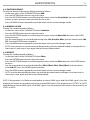
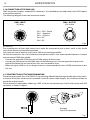
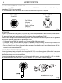
3.17 CONSTRUCTION OF THE DMX TERMINATION
The termination avoids the risk of DMX 512 signals being reected back along the cable when they reach-
es the end of the line: under certain conditions and with certain cable lengths, this could cause them to
cancel the original signals.
The termination is prepared by soldering a 120Ω 1/4 W resistor between pins 2 and 3 of the 5-pin male XLR
connector, as shown in gure.
Fig.6
DMX - OUTPUT
XLR socket
DMX - INPUT
XLR plug
Pin1 : GND - Shield
Pin2 : - Negative
Pin3 : + Positive
Pin4 : N/C
Pin5 : N/C
Fig.7
Example:
5 pin XLR connector

13
ARCPOD27Q
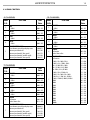
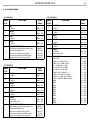
3.18 DMX CONTROL
5 CHANNEL
MODE
FUNCTION DMX
Value
5 Ch
1
RED
0~100% 000 - 255
2
GREEN
0~100% 000 - 255
3
BLUE
0~100% 000 - 255
4
WHITE
0~100% 000 - 255
5
DIMMER SPEED MODE
Preset dimmer speed from display menu
Dimmer speed mode o
Dimmer speed mode1 (fast speed)
Dimmer speed mode2 (middle speed)
Dimmer speed mode3 (slow speed)
000-051
052-101
102-152
153-203
204-255
10 CHANNEL
MODE
FUNCTION DMX
Value
10 Ch
1
DIMMER
0~100% 000 - 255
2
RED
0~100% 000 - 255
3
GREEN
0~100% 000 - 255
4
BLUE
0~100% 000 - 255
5
WHITE
0~100% 000 - 255
6
STROBE
No function
Strobe Slow to Fast
000 - 010
011 - 255
7
COLOR MACRO
No Function
R 100%, G 0~100%, B 0 %
R 100%~0 %, G 100%, B 0 %
R 0 %, G 100%, B 0~100%
R 0 %, G 100~0 %, B 100%
R 0~100%, G 0 %, B 100%
R 100%, G 0 %, B 100~0 %
R 100%, G 0~100%, B 0~100%
R 100~0 %, G 100~0 %, B 100%
R 100%, G 100%, B 100%, W 100%
2800k
3000k
3200k
4000k
5600k
6000k
6500k
7000k
8000k
9000k
10000k
000 - 010
011 - 030
031 - 050
051 - 070
071 - 090
091 - 110
111 - 130
131 - 150
151 - 170
171 - 200
201 - 205
206 - 210
211 - 215
216 - 220
221 - 225
226 - 230
231 - 235
236 - 240
241 - 245
246 - 250
251 - 255
7 CHANNEL
MODE
FUNCTION DMX
Value
7 Ch
1
DIMMER
0~100% 000 - 255
2
RED
0~100% 000 - 255
3
GREEN
0~100% 000 - 255
4
BLUE
0~100% 000 - 255
5
WHITE
0~100% 000 - 255
6
STROBE
No function
Strobe Slow to Fast
000 - 010
011 - 255
7
DIMMER SPEED MODE
Preset dimmer speed from display menu
Dimmer speed mode o
Dimmer speed mode1 (fast speed)
Dimmer speed mode2 (middle speed)
Dimmer speed mode3 (slow speed)
000-051
052-101
102-152
153-203
204-255

ARCPOD27Q
14
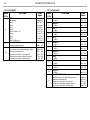
13 CHANNEL
MODE
FUNCTION DMX
Value
13 Ch
1
RED 1
0~100% 000 - 255
2
GREEN 1
0~100% 000 - 255
3
BLUE 1
0~100% 000 - 255
4
WHITE 1
0~100% 000 - 255
5
RED 2
0~100% 000 - 255
6
GREEN 2
0~100% 000 - 255
7
BLUE 2
0~100% 000 - 255
8
WHITE 2
0~100% 000 - 255
9
RED 3
0~100% 000 - 255
10
GREEN 3
0~100% 000 - 255
11
BLUE 3
0~100% 000 - 255
12
WHITE 3
0~100% 000 - 255
13
DIMMER SPEED MODE
Preset dimmer speed from display menu
Dimmer speed mode o
Dimmer speed mode1 (fast speed)
Dimmer speed mode2 (middle speed)
Dimmer speed mode3 (slow speed)
000-051
052-101
102-152
153-203
204-255
10 CHANNEL
MODE
FUNCTION DMX
Value
10 Ch
8
EFFECTS
NO Function
Eect 1
Eect 2
Eect 3
Eect4
Eect5 (Eects1- 4)
Eect 6
Eect 7
Eect 8
Eect 9 (Eects6- 8)
000-010
011-037
038-064
065-091
092-118
119-145
146-172
173-199
200-226
227-255
9
EFFECTS SPEED
Eects speed slow to fast 000 - 255
10
DIMMER SPEED MODE
Preset dimmer speed from display menu
Dimmer speed mode o
Dimmer speed mode 1 (fast speed)
Dimmer speed mode 2 (middle speed)
Dimmer speed mode 3 (slow speed)
000 - 051
052 - 101
102 - 152
153 - 203
204 - 255

15
ARCPOD27Q
17 CHANNEL
MODE
FUNCTION DMX
Value
17 Ch
1
DIMMER
0~100% 000 - 255
2
STROBE 1
No function
Strobe Slow to Fast
000 - 010
011 - 255
3
STROBE 2
No function
Strobe Slow to Fast
000 - 010
011 - 255
4
STROBE 3
No function
Strobe Slow to Fast
000 - 010
011 - 255
5
RED 1
0~100% 000 - 255
6
GREEN 1
0~100% 000 - 255
7
BLUE 1
0~100% 000 - 255
8
WHITE 1
0~100% 000 - 255
9
RED 2
0~100% 000 - 255
10
GREEN 2
0~100% 000 - 255
11
BLUE 2
0~100% 000 - 255
12
WHITE 2
0~100% 000 - 255
13
RED 3
0~100% 000 - 255
14
GREEN 3
0~100% 000 - 255
15
BLUE 3
0~100% 000 - 255
16
WHITE 3
0~100% 000 - 255
17
DIMMER SPEED MODE
Preset dimmer speed from display menu
Dimmer speed mode o
Dimmer speed mode1 (fast speed)
Dimmer speed mode2 (middle speed)
Dimmer speed mode3 (slow speed)
000-051
052-101
102-152
153-203
204-255

ARCPOD27Q
16
- 4 - MAINTENANCE
4.1 MAINTENANCE AND CLEANING THE UNIT
• Make sure the area below the installation place is free from unwanted persons during setup.
• Switch o the unit, unplug the main cable and wait until the unit has cooled down.
• All screws used for installing the device and any of its parts should be tightly fastened and should not
be corroded.
• Housings, xations and installation spots (ceiling, trusses, suspensions) should be totally free from any
deformation.
• When the lens is visibly damaged due to cracks or deep scratches, it must be replaced.
• The main cables must be in impeccable condition and should be replaced immediately even when a
small problem is detected.
• In order to protect the device from overheating the cooling fans (if any), and ventilation openings
should be cleaned monthly.
To ensure optimal operation and performance for a long time it is essential to periodically clean the parts
subject to dust and grease deposits. The frequency with which the following operations are to be carried
out depends on various factors, such as the amount of the eects and the quality of the working environ-
ment (air humidity, presence of dust, salinity, etc.). Use a soft cloth dampened with any detergent liquid
for cleaning glass to remove the dirt from the reectors, from the lenses and lters.
It is recommended that the projector undergoes an annual service by a qualied technician for special
maintenance involving at least the following operations:
- General cleaning of internal parts..
- Restoring lubrication of all parts subject to friction, using lubricants specically.
- General visual check of the internal components, cabling, mechanical parts, etc.
- Electrical, photometric and functional checks; eventual repairs.
Warning: we strongly recommend internal cleaning to be carried out by qualied personnel!
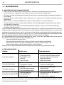
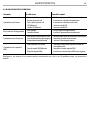
4.2 TROUBLESHOOTING
Problems Possible causes Checks and remedies
Fixture does not light up
• No mains supply
• Dimmer fader set to 0
• All color faders set to 0
• Faulty LED
• Faulty LED board
• Check the power supply voltage
• Increase the value of the dimmer channels
• Increase the value of the color channels
• Replace the LED board
• Replace the LED board
General low light intensity
• Dirty lens assembly
• Misaligned lens assembly
• Clean the xture regularly
• Install lens assembly properly
Fixture does not power up
• No power
• Loose or damaged power cord
• Faulty internal power supply
• Check for power on power outlet
• Check power cord
• Replace internal power supply
Fixture does not respond to DMX
• Wrong DMX addressing
• Damaged DMX cables
• Bouncing signals
• Check control panel and unit addressing
• Check DMX cables
• Install terminator as suggested
Contact an authorized service center in case of technical problems or not reported in the table can not be
resolved by the procedure given in the table.


REV. 03-11/19
Music & Lights S.r.l. si riserva ogni diritto di elaborazione in qualsiasi forma delle presenti istruzioni per l’uso.
La riproduzione - anche parziale - per propri scopi commerciali è vietata.
Al ne di migliorare la qualità dei prodotti, la Music&Lights S.r.l. si riserva la facoltà di modicare, in qualun-
que momento e senza preavviso, le speciche menzionate nel presente manuale di istruzioni.
Tutte le revisioni e gli aggiornamenti sono disponibili nella sezione 'Manuali' sul sito www.musiclights.it
La pagina sta caricando ...
La pagina sta caricando ...
La pagina sta caricando ...
La pagina sta caricando ...
La pagina sta caricando ...
La pagina sta caricando ...
La pagina sta caricando ...
La pagina sta caricando ...
La pagina sta caricando ...
La pagina sta caricando ...
La pagina sta caricando ...
La pagina sta caricando ...
La pagina sta caricando ...
La pagina sta caricando ...
La pagina sta caricando ...
La pagina sta caricando ...
La pagina sta caricando ...
La pagina sta caricando ...
La pagina sta caricando ...
La pagina sta caricando ...
-
 1
1
-
 2
2
-
 3
3
-
 4
4
-
 5
5
-
 6
6
-
 7
7
-
 8
8
-
 9
9
-
 10
10
-
 11
11
-
 12
12
-
 13
13
-
 14
14
-
 15
15
-
 16
16
-
 17
17
-
 18
18
-
 19
19
-
 20
20
-
 21
21
-
 22
22
-
 23
23
-
 24
24
-
 25
25
-
 26
26
-
 27
27
-
 28
28
-
 29
29
-
 30
30
-
 31
31
-
 32
32
-
 33
33
-
 34
34
-
 35
35
-
 36
36
-
 37
37
-
 38
38
-
 39
39
-
 40
40


ProLights ARCPOD27Q Manuale utente
- Categoria
- Stroboscopi
- Tipo
- Manuale utente
in altre lingue
- English: ProLights ARCPOD27Q User manual
Documenti correlati
-
ProLights 10W RGBW/FC outdoor IP66 accent light Manuale utente
-
-
-
-
-
-
-
-