LG PQRCVSL0QW.ENCXUAE Guida d'installazione
- Tipo
- Guida d'installazione

ENGLISH
LG
New Wide Wired Remote Controller
LG
IMPORTANT
• Please read this owner's & installation manual completely
before installing the product.
• Installation work must be performed in accordance with the
national wiring standards by authorized personnel only.
• Please retain this owner's & installation manual for future
reference after reading it thoroughly.
Owner's & Installation Manual
Models: PQRCVSL0
PQRCVSL0QW
P/No.: MFL62129202
ITALIANO ESPAÑOL
FRANÇAIS
DEUTSCH
êìëëäàâ
PORTUGUÊS

Safety Precaution
Owner’s & Installation Manual 3
ENGLISH
2 New Wide Wired Remote Controller
New Wide Wired Remote Controller Owner’s & Installation Manual
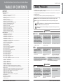
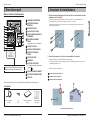
TABLE OF CONTENTS
Safety Precaution .....................................................................................................................................................3
Part Description........................................................................................................................................................4
Installation Instructions...........................................................................................................................................5
Group control .........................................................................................................................................................7
Installer Setting - How to Enter Installer Setting Mode...........................................................................................8
Installer Setting - Test Run Mode.........................................................................................................................11
Installer Setting - Setting Address of Central Control...........................................................................................12
Installer Setting - E.S.P. .......................................................................................................................................13
Installer Setting - Thermistor ................................................................................................................................15
Installer Setting - Ceiling Height Selection ...........................................................................................................16
Installer Setting - Static Pressure Setting.............................................................................................................17
Installer Setting - Remote Controller Master/Slave Setup ...................................................................................18
Installer Setting - Override Master/Slave Setting .................................................................................................19
Installer Setting - Dry Contact Mode Setting ........................................................................................................20
Installer Setting - Zone State................................................................................................................................21
Installer Setting - Celsius / Fahrenheit Switching.................................................................................................22
Installer Setting - Zone Type Setting....................................................................................................................23
Installer Setting - Zone Number Setting ...............................................................................................................24
Installer Setting - Emergency Heater Setting ......................................................................................................25
Installer Setting - Option Function Setting............................................................................................................27
Installer Setting - Static Pressure Step Setting ....................................................................................................28
Owner's Instructions..............................................................................................................................................29
Standard Operation - Standard Cooling...............................................................................................................29
Standard Operation - Power Cooling ...................................................................................................................30
Standard Operation - Heating Mode ....................................................................................................................30
Standard Operation - Dehumidification Mode ......................................................................................................31
Standard Operation - Fan Mode ..........................................................................................................................31
Standard Operation - Auto Operation Mode ........................................................................................................32
Standard Operation - Temperature Setting/Room Temperature Check ..............................................................33
Standard Operation - Airflow Setting....................................................................................................................34
Sub function - Direct Wind / Indirect Wind .........................................................................................................35
Sub function - Plasma Purification .......................................................................................................................37
Sub function - Humidifier......................................................................................................................................38
Sub function - Electric Heater ..............................................................................................................................39
Sub function - Energy-Saving Cooling Operation ................................................................................................40
Sub function - Robot Cleaning Manual Setup ......................................................................................................41
Function setting - Child Lock................................................................................................................................42
Function setting - Robot Cleaning Automatic Setup ............................................................................................43
Function setting - Filter Sign Clear.......................................................................................................................44
Function setting - Elevation Grill ..........................................................................................................................45
Function setting - Vane Angle Control .................................................................................................................46
Function Setting - Change Temp .........................................................................................................................47
Function setting - Zone Control............................................................................................................................48
Function setting - Changing Current Time ..........................................................................................................49
Function setting - Auto Cleaning .........................................................................................................................51
Function Setting – WLAN(Wireless LAN) Module Access Point mode ................................................................52
Programming - Simple Reservation .....................................................................................................................53
Programming - Sleep Reservation .......................................................................................................................54
Programming - ON Reservation...........................................................................................................................55
Programming - OFF Reservation ..................................................................................................
.......................57
Programming - Weekly Reservation ....................................................................................................................59
Programming - Holiday Reservation ....................................................................................................................61
Ventilation Product User Manual - Interlinked Air Conditioner and Ventilation ....................................................62
Ventilation Product User Manual - Interlinked Operation with General Ventilation ..............................................63
Manual Conversion ..............................................................................................................................................64
Ventilation Product User Manual - Interlinked Operation with Direct Expansion Ventilation................................65
Ventilation Product User Manual - Single Operation with Direct Expansion Ventilation ......................................66
Ventilation Product Additional Operations - Fast / Power Saving ........................................................................67
Ventilation Product Function Settings ..................................................................................................................68
Ventilation Product Reservations Settings ...........................................................................................................69
Ventilation Product Installer Setting Functions - Entering Method .......................................................................70
Different Mode Drive ............................................................................................................................................71
Self-diagnosis for Trouble Mode ..........................................................................................................................72
Outage Compensation Function ..........................................................................................................................72
Troubleshooting Steps .........................................................................................................................................73
Entrust installation of the
product to a licensed HVAC
technician. Failure to do so may
result in fire, electric shock,
explosion, and/or physical injury.
• It will cause fire or electric shock
or explosion or injury.
All requests for replacement
or reinstallation should be to
a licensed HVAC technician.
• It will cause fire or electric shock
or explosion or injury.
Do not disassemble, fix,
and/or modify products
randomly.
• It will cause fire or electric shock.
Do not place flammable
substances close to the
product.
• It will cause fire.
Do not allow water to run
into the product.
• It will cause electric shock or
breakdown.
Do not give the shock to the
product.
• It will cause breakdown when
giving the shock to the product.
n Installation
Safety Precaution
• The installation requires expert skills, and it should be installed by the service center or other shops specialized
in the installation and recognized by our company.
• For all the problems arising after installation by someone who has no relevant qualifications, our company will
not provide free service.
• The following safety precautions are provided to prevent unexpected dangers or losses.
: If the user does not follow the mandatory items, it may result in serious injury or death.
: If the user does not follow the mandatory items, it may cause personal injury or property
damage.
: Warnings and Cautions are to call the user’s attention to the possible danger. Read and follow
them carefully in order to prevent a safety accident.
: Warning and Caution are indicated in this guide and the product itself to help protect the users
from danger.
WARNING
CAUTION
WARNING
n In-use
Refer to the service center or installation
specialty store when the product becomes wet.
• It will cause fire or electric shock.
Do not give the shock using sharp and
pointed objects.
• It will cause breakdown by damaging parts.
n In-use
CAUTION
Entrust installation of the
product to a licensed HVAC
technician. Failure to do so may
result in fire, electric shock,
explosion, and/or physical injury.
• It will cause fire or product
deformation.
Do not press hard against
the screen, and only select
more than one button at a
time if instructed to do so in
the user instructions.
• It will cause product breakdown or
malfunction.
Do not touch or pull the lead
wire with wet hands.
• It will cause product breakdown or
electric shock.

1
4
5
7
11
10
9
8
2
3
6
13
12
14
15
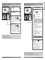
Attach the appropriate language information label
inside the front door for convenient access.
Owner’s & Installation Manual 5
ENGLISH
4 New Wide Wired Remote Controller
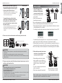
Installation Instructions
2
2
1
3
3
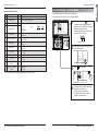
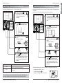
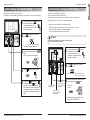
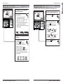
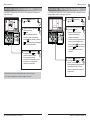
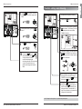
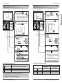
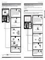
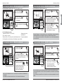
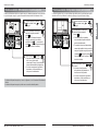
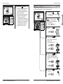
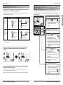
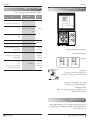
1. Please fix tightly using the provided screws after placing remote controller setup
board on the place where you plan to place the remote controller.
- Please set it up not to bend because poor setup could take place if setup board bends.
Please set up remote controller board fit to the reclamation box if there is a reclamation box. is unclear and
needs to be heavily reworded.
- Install the product so as not to make a gap with the wall side to prevent shaking after the installation.
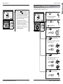
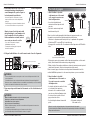
2. The wired remote controller can be set up in three different directions.
- Direction: through the wall, top, or right.
- If setting up the remote controller cable to exit through the top or right side, be sure to remove the plastic from
the guide grooves from the remote controller case.
h
Remove guide groove with long nose.
①
Through the wall
②
Through the top
③
Through the right side
Installation Instructions
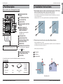
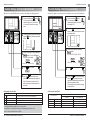
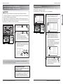
Part Description
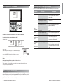
Part Description
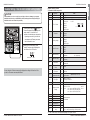
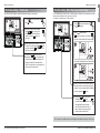
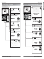
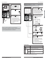
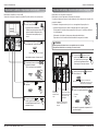
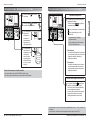
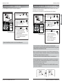
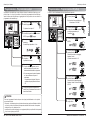
Name and Function of Remote Controller
OPERATION INDICATION
SCREEN
SET TEMPERATURE BUTTON
FAN SPEED BUTTON
ON/OFF BUTTON
OPERATION MODE SELECTION
BUTTON
WIRELESS SIGNAL (IR)
RECEIVER FOR WIRELESS
REMOTE CONTROLLER
• Only Operate with ceiling Duct
type indoor unit
AIR FLOW BUTTON
SUBFUNCTION BUTTON
FUNCTION SETTING BUTTON
VENTILATION BUTTON
RESERVATION
UP,DOWN,LEFT,RIGHT BUTTON
• To check the indoor temperature,
press button.
ROOM TEMPERATURE BUTTON
SETTING/CANCEL BUTTON
EXIT BUTTON
1
2
3
4
5
6
7
8
9
10
11
12
13
14
15
Connection Cable
(1EA, 10m)
Screw
(4 EA)
Owner's / Installation
manual
Inform label
(8EA-8Languages)
Accessories
j Some functions may not be operated and displayed depending on the product type.
Wire guide grooves

Owner’s & Installation Manual 7
ENGLISH
Installation Instructions
6 New Wide Wired Remote Controller
Installation Instructions
GND
GND
12V
Signal wire
Signal wire
GND
12V
B Y R B Y R
MASTER SLAVE
Signal wire
GND
12V
Signal wire
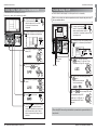
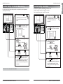
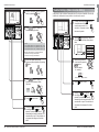
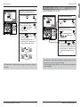
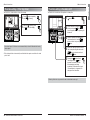
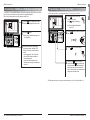
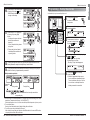
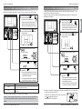
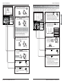
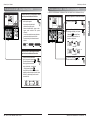
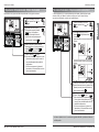
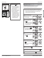
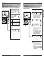
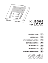
Group control
1. When installing more than 2
units of air conditioner to one
wired remote controller, please
connect as pictured to the right
• This needs more clarification before
it can be edited
• Check for event communication
through the product manual.
2. When installing more than 2 wired remote
controllers to one air conditioner, please
connect as pictured to the right.
• When installing more than 2 units of wired
remote controller to one air conditioner, set
one wired remote controller as master and the
others all as slaves, as shown in the right
picture.
• You cannot control the group as shown in the
right for some products.
• Refer to the product manual for more details.
When controlling multiple indoor units with event communication function with one remote
controller, you must change the master/slave setting from the indoor unit.
- When changing the master/slave configuration, changes will take effect after the unit is turned
on after being powered off for one minute.
- For ceiling type cassette and duct product group, change the switch setting of the indoor PCB.
- For wall-mount type and stand type indoor units, change the master/slave setting with the
wireless remote controller. (Refer to wireless remote controller manual for details)
h When installing 2 remote controllers to one indoor unit with event communication function, set
the master/slave of the remote controller. (Refer to remote controller master/slave selection)
When in a slave setting, some functions(fan speed, lock and time setting) may not be available.
When simultaneously connecting
2 sets of wired remote controller
• When controlling in groups, set the master/slave of the remote controller. Refer to Installer
setting section on how to set master/slave for more details.
#3 switch OFF: Master
(Factory default setting)
#3 switch ON: Slave
Wall
Side
Wall
Side
Wall
Side
Wall
Side
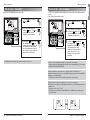
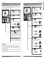
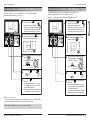
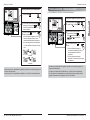
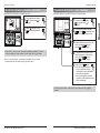
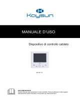
Connecting order
Separating order
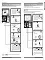
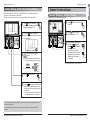
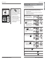
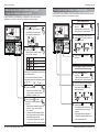
3. Place the top part of the remote controller into
the setup board you have screwed into the wall,
as pictured to the right, and connect the pieces
by pressing the bottom into the board.
- Arrange the cable through the top or right guide grooves before
closing if necessary, and do not leave a gap between the
remote controller and the setup board.
To separate the remote controller from the
setup board, insert a flathead screw driver into
the separation holes on the bottom of the
remote controller and turn clockwise to release
the remote controller.
- There are two separating holes on the remote controller, and
they should be separated individually. Make sure not to
damage any interior components with the screwdriver when
separating.
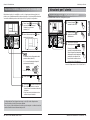
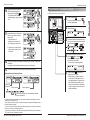
4. Please connect indoor unit and remote controller using connection cable.
5. Please use an extension cable if the distance between the wired remote controller
and indoor unit is more than 10m.
Please check if connector is normally connected.
Connecting cable
Indoor
Unit side
When installing the wired remote controller, do not bury it in the wall.
(It can cause damage in the temperature sensor.)
Do not install the cable to be 50m or above.
(It can cause communication error.)
• When installing the extension cable, check the connecting direction of the connector of the remote controller
side and the product side for correct installation.
• If you install the extension cable in the opposite direction, the connector will not be connected.
• Specification of extension cable: 2547 1007 22# 2 core 3 shield 5 or above.
CAUTION
• Installation work must be performed in accordance with the national wiring standards by authorized
personnel only.
• Installations must comply with the applicable local/national or international standards.
• Apply a totally enclosed noncombustible conduit (metal raceway) if local electric and building codes require
plenum cable usage.
CAUTION
12V Red
Signal Yellow
GND Black

Owner’s & Installation Manual 9
ENGLISH
8 New Wide Wired Remote Controller
Installation Instructions
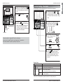
Installer Setting Code Table
1) General air-conditioner product
j Some contents may not be displayed depending on the product function
Installation Instructions
If the installation is not done correctly it can cause injury to the user or damage to your property.
Installation must be done by a certified HVAC technician, and any problems arising from improper
installation are the owner’s financial responsibility.
CAUTION
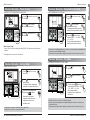
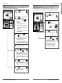
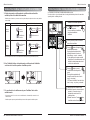
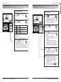
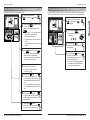
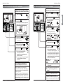
Installer Setting - How to enter installer setting mode
Function Code Value
Pressing and holding the button for
3 seconds enters the remote controller
setup mode. If it is not held for 3
seconds, it enters the user setup mode.
- If pressing once shortly, it enters into
user setup mode. Please press more
than 3 seconds for sure.
1
When you enter the setting mode
initially, Function code is displayed on
the bottom of the LCD screen.
2
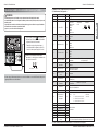
No. Function Code Value
1 Test Run 01 01:Set
2 Address Setting 02 00~FF : Address
<ESP Step> <ESP Value> <Example>
01:VeryLow 0 ~ 255
02:Low
3 E.S.P. Value 03
03:Med
04:High
05:Very High
01:Remo
4 Thermistor 04 02:Indoor
03:2TH
01:Low
02:Med
5 Ceiling Height 05
03:High
04:Very High
01:V-H
02:F-H
6 Static Pressure 06
03:V-L
04:F-L
7 Master Setting 07
00:Slave
※ If only “Plus1” series models 00 : Group setting
01:Master
01 : Single setting
8 Override Setting 08
00:Slave
01:Master
9 Dry Contact 09
00:Auto-Off
01:Auto-On
10
Release 3 Min.
10 01:Set
Delay
11 Zone State 11
01:Variable
02:Fixed
12
Celsius
12
00:Celsius
(Optimized only for U.S.A)
Fahrenheit Switching 01:Fahrenheit
13 Zone Type 13
00:Zone Controller
01:Damper Controller
14 Zone Number 14 02~04(Zone number)
Emergency Heater
15
Setting
18
16 Plasma 20
17 Electric heater 21
18 Humidifier 22
00: Not Installed
19 Elevation Grill 23
01: Installed
20 Ventilation Kit 24
21 Auxiliary Heater 25
22
Static Pressure
32
00: use static pressure (code 06) set value
Step 01~ 11: static pressure step (code 32) set value
Function Code ESP valueESP step
•
Some categories of the menu may not be displayed according to the function of the
product, or the menu name may be different.
Select mode Setup Low Ambient Heating Operation Setup FAN Speed
00 : not use 0 : not use 0 : fan off
01 : use 1 : use – compressor off(0℉/-18℃)/on(5℉/-15℃) 1 : fan on
2 : use – compressor off(5℉/-15℃)/on(10℉/-12℃)
3 : use – compressor off(10℉/-12℃)/on(15℉/-9℃)

Owner’s & Installation Manual 11
ENGLISH
Installation InstructionsInstallation Instructions
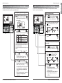
Function Code Set
Press button to start.
3
During the test run, pressing the below
buttons will exit the test run:
- Select operation, temperature
up/down, wind flow control, wind
direction, start/stop button.
4
Pressing and holding the button for
3 seconds enters the remote controller
setup mode. If it is not held for 3 seconds,
it enters the user setup mode.
- Please cancel the right and left of wind
direction for RAC product.
1
Setup figure '01' blinks at the lower part
of indication window.
2
Installer Setting - Test Run Mode
After installing the product, you must run a Test Run mode.
For details related to this operation, refer to the product manual.
10 New Wide Wired Remote Controller
2) General Ventilation product
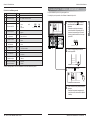
j Some contents may not be displayed depending on the product function
No. Function Code Value
1 Test Run 01 01 : Test Run Setup
2 02 00~FF : Address of Central Control
3 SA(Supply Air) ESP 03 <ESP level> <ESP value> <Example>
4 EA(Exhaust Air) ESP 04
01 : Low 0~255
02 : High
03 : Super High
5 Product Direction 05
01 : Normal
02 : Opposite
6 Quick Refresh Priority 06
01 : Supply Air First
02 : Exhaust Air First
7 Master Setting 07
00 : Slave
01 : Master
8 Override Setting 08
00 : Slave
01 : Master
9 Dry Contact 09
00 : Auto-Off
01 : Auto-On
10 Release Of 3 Minute Delay 10 01 : Set
11 Zone State 11
01 : Variable
02 : Fixed
12
Humidification for Singular
13
00 : Not in Use
Ventilation 01 : Use
13
Humidification for Heat Mode
14
00 : Automatic
Ventilation 01 : Manual
Address Setting
Function Code ESP valueESP step

Owner’s & Installation Manual 13
ENGLISH
12 New Wide Wired Remote Controller
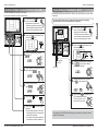
Installation Instructions
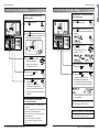
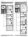
If entering into ESP setup mode by using
button, it indicates as pictured below.
2
Select ESP fan step by pressing
button. (01: very low, 02: low,
03: medium, 04: high, 05: very high)
3
Move to ESP value setting by pressing
button.
(It is 000 when delivered
from the warehouse.)
4
Press button to setup ESP value.
(It is possible to set up ESP
value from 1 to 255, and 1 is
the smallest and 255 is the
biggest.)
5
Function code,
ESP code
ESP value
Pressing and holding the
button for 3 seconds enters the
remote controller setup mode. If it
is not held for 3 seconds, it enters the
user setup mode.
1
Function Code ESP value
ESP step
Installer Setting - E.S.P.
• If ESP is set incorrectly the air conditioner may malfunction, which is why this setting should only be
done by a certified technician.
This function allows the wind strength for each fan speed level to be set manually.
It's the function to use for connecting central control.
Please refer to central controller manual for the details
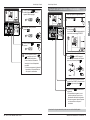
Function Code
Group No
Indoor No.
Set Group No. by pressing
button.(0~F)
3
Move to Indoor No. setting option
by pressing button.
4
Set Indoor No. by pressing
button.
5
Press button to save.
6
Pressing the button will exit the settings
mode. If is not pressed, the remote
controller will automatically exit setup mode
after 25 seconds with no input. If the set
button is not pressed, the changes will not
take effect.
7
If entering into address setup mode by using
button, it indicates as pictured below.
2
1
Pressing and holding the button
for 3 seconds enters the remote
controller setup mode. If it is not held
for 3 seconds, it enters the user
setup mode.
Installation Instructions
Installer Setting - Setting Address of Central Control
•
When setting ESP value on the product without very weak wind or power wind function, it
may not work.

Owner’s & Installation Manual 15
ENGLISH
14 New Wide Wired Remote Controller
Installation Instructions
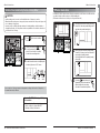
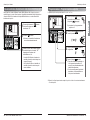
Function Code Thermistor setting
Set Thermistor value by pressing
button. (01: Remote Controller,
02: Indoor, 03: 2TH)
3
Press button to save.
4
5
If moving to room temperature perception
sensor selection menu by pressing
button, it indicates as pictured below.
2
Pressing and holding the button
for 3 seconds enters the remote
controller setup mode. If it is not held
for 3 seconds, it enters the user setup
mode.
1
Pressing the button will exit the settings
mode. If is not pressed, the remote
controller will automatically exit setup mode
after 25 seconds with no input. If the set
button is not pressed, the changes will not
take effect.
Installer Setting - Thermistor
j The function of 2TH has different operation characteristics according to the product.
Temperature sensor selection Function
01 Remote controller Operation in remote controller temperature sensor
02 Indoor unit Operation in indoor unit temperature sensor
03 2TH
Cooling
Operation of higher temperature by comparing indoor unit's and wired
remote controller’s temperature.
(There are products that operate at a lower temperature.)
Heating
Operation of lower temperature by comparing indoor unit's and wired remote
controller's temperature.
Thermistor Table
Installation Instructions
Function code,
ESP code
ESP value
Press button to save.
7
Select ESP fan step again by using
button and set up the ESP value, as No.
4 and 5, that corresponds to each wind
flow.
6
Pressing the button will exit the
settings mode. If is not pressed, the
remote controller will automatically exit
setup mode after 25 seconds with no
input. If the set button is not pressed, the
changes will not take effect.
8
• Please be careful not to change the ESP value for each fan step.
• It does not work to setup ESP value for very low/power step for some products.
• ESP value is available for specific range belongs to the product.
This is the function to select the temperature sensor to judge the room temperature.

Owner’s & Installation Manual 17
ENGLISH
16 New Wide Wired Remote Controller
Installation Instructions
Function Code Pressure
Press and hold the button
for 4 seconds to enter the
installer setting mode. The timer
will display 01:01.
1
Select static pressure by pressing
button.
(01:V-H, 02:F-H, 03:V-L, 04:F-L)
3
Press button to save.
4
5
Pressing the button will exit the settings
mode. If is not pressed, the remote
controller will automatically exit setup mode
after 25 seconds with no input.
If the set button is not pressed, the changes
will not take effect.
If pressing button repeatedly, it
moves to static pressure selection menu
as pictured below.
2
Installer Setting - Static Pressure Setting
This function is applied to only duct type indoor units. Setting this in other cases will cause malfunction.
Pressure selection
Function
Zone state ESP standard value
01 V-H Variable High
02 F-H Fixed High
03 V-L Variable Low
04 F-L Fixed Low
Static Pressure Setting Table
Function Code Thermistor setting
Select ceiling height value by pressing
button. (01:Low, 02:Medium,
03:High, 04:Very high)
3
Press button to save.
4
5
If moving to ceiling height selection menu by
pressing button, it indicates as pictured
below.
2
Pressing and holding the button
for 3 seconds enters the remote
controller setup mode. If it is not held
for 3 seconds, it enters the user setup
mode.
1
Pressing the button will exit the settings
mode. If is not pressed, the remote
controller will automatically exit setup mode
after 25 seconds with no input. If the set
button is not pressed, the changes will not
take effect.
Installation Instructions
Installer Setting - Ceiling Height Selection
This function is to adjust FAN Airflow rate according to ceiling height (for ceiling type product)
• Ceiling height setting is available only for some products.
• Ceiling height of ‘Very high’ function may not exist depending on the indoor unit.
• Refer to the product manual for more details.
Ceiling Height Level Description
01 Low Decrease the indoor airflow rate 1 step from standard level
02 Medium Set the indoor airflow rate as standard level
03 High Increase indoor airflow rate 1 step from standard level
04 Very high Increase indoor airflow rate 2 steps from standard level
Ceiling Height Selection Table

Owner’s & Installation Manual 19
ENGLISH
18 New Wide Wired Remote Controller
Function Code Master/Slave
Select Master/ Slave by pressing
button.
(00: Slave, 01 : Master)
3
Pressing and holding the button
for 3 seconds enters the remote
controller setup mode. If it is not held
for 3 seconds, it enters the user setup
mode.
1
If pressing button repeatedly, it moves to
override master/slave selection menu as
pictured below.
2
Press button to save.
4
Pressing the button will exit the settings
mode. If is not pressed, the remote
controller will automatically exit setup mode
after 25 seconds with no input. If the set
button is not pressed, the changes will not
take effect.
5
Installation Instructions
Installer Setting - Override Master/Slave Setting
Override master/slave selection function to prevent indoor units operate as cooling and heating mode
at same time.
Override slave set indoor units are operated flow master indoor unit’s mode.
Installation Instructions
Installer Setting - Remote Controller Master/Slave Setup
Function Code Master/Slave value
Select Master/ Slave by pressing
button.
(00: Slave, 01: Master)
3
Press button to save.
4
Pressing and holding the button
for 3 seconds enters the remote
controller setup mode. If it is not held
for 3 seconds, it enters the user
setup mode.
1
If pressing button repeatedly, it moves to
master/slave selection menu as pictured
below.
2
Pressing the button will exit the settings
mode. If is not pressed, the remote
controller will automatically exit setup mode
after 25 seconds with no input. If the set
button is not pressed, the changes will not
take effect.
5
It is a function for settings in group control, or 2-remote controller control.
Remote controller Function
Master
Indoor unit operates based on master remote controller at group control.
(Master is set when delivered from the warehouse.)
Slave
Setup all remote controllers except one master remote controller to slave at
group control
• When controlling in groups, basic operation settings, airflow strength weak/medium/strong,
lock setting of the remote controller, time settings, and other functions may be restricted.
h Refer to the 'group control' part for details
h Override master/slave selection function is possible to use only when it is connected to the
succeeding models of Multi-V 7 series.
• If it is set as Override Slave, icon
is displayed on LCD Display Window. (See Figure 1)
Figure 1.

Owner’s & Installation Manual 21
ENGLISH
20 New Wide Wired Remote Controller
Function Code Zone State
fixing mode
Select Zone State rate fixing mode by
pressing button.
(01: Variable, 02: Fixed)
3
Press button to save.
4
Pressing and holding the button
for 3 seconds enters the remote
controller setup mode. If it is not held
for 3 seconds, it enters the user
setup mode.
1
If moving to ceiling height selection menu by
pressing button, it indicates as pictured
below.
2
Pressing the button will exit the settings
mode. If is not pressed, the remote
controller will automatically exit setup mode
after 25 seconds with no input. If the set
button is not pressed, the changes will not
take effect.
5
Installation Instructions
Installer Setting - Zone State
It is the function to setup indoor unit's wind flow to variable or fixed.
- Variable : Comp ON, setup airflow. Comp OFF, weak wind
- Fixed : Comp ON, setup airflow. Comp OFF, setup airflow
Installation Instructions
Installer Setting - Dry Contact Mode Setting
Function Code Dry Contact
setting value
Select Dry contact setting by pressing
button.
(00 : Manual, 01 : Automatic)
3
Press button to save.
4
Pressing and holding the button
for 3 seconds enters the remote
controller setup mode. If it is not held
for 3 seconds, it enters the user setup
mode.
1
If pressing button repeatedly, it moves to
remote controller dry contact mode setup
menu as pictured below.
2
Pressing the button will exit the settings
mode. If is not pressed, the remote
controller will automatically exit setup mode
after 25 seconds with no input. If the set
button is not pressed, the changes will not
take effect.
5
Dry contact function is the function that is possible to use only when dry contact equipment is
separately purchased/setup.
• Please refer to dry contact manual for more details.

Owner’s & Installation Manual 23
ENGLISH
Installation Instructions Installation Instructions
22 New Wide Wired Remote Controller
Installer Setting - Celsius / Fahrenheit Switching
Function Code conversion mode value
Press repeatedly until it shows
Function code 12.
2
Select Temperature unit mode by
pressing button.
(00: Celsius, 01: Fahrenheit)
3
Press button to save or release.
4
Pressing the button will exit
the settings mode. If is not
pressed, the remote controller will
automatically exit setup mode after 25
seconds with no input. If the set button is
not pressed, the changes will not take
effect.
5
1
Pressing and holding the button for
3 seconds enters the remote
controller setup mode. If it is
not held for 3 seconds, it enters
the user setup mode.
Function Code Zone type value
Repeat pressing button to select
Function code 13.
Ex) Setting the Zone Type as "New"
2
Select Zone Type by pressing
button
(00:Old, 01:New)
3
Press button to save or release.
4
1
Pressing and holding the button for
3 seconds enters the remote
controller setup mode. If it is
not held for 3 seconds, it enters
the user setup mode.
Pressing the button will exit
the settings mode. If is not
pressed, the remote controller will
automatically exit setup mode after 25
seconds with no input. If the set button is
not pressed, the changes will not take
effect.
5
This function is used for switching the display between Celsius and Fahrenheit.
h Whenever press button in Fahrenheit mode, the temperature will increase/drop 2
degrees.
Installer Setting - Zone Type Setting
This function is only available on some products.
It is possible to set up a new zone or select an old one to install the damper controller.
If you set zone number incorrectly, the product may malfunction especially in zone control.
This function must carried out by a certificated-technician.
CAUTION

Owner’s & Installation Manual 25
ENGLISH
24 New Wide Wired Remote Controller
Installation Instructions Installation Instructions
Function Code Zone Number installed
Press repeatedly until it shows
Function code 14.
Ex) Setting the Zone Number for "2"
2
Select Zone Number by pressing
button
(02~04 : number of zone installed)
3
Press button to save or release.
4
1
Pressing and holding the button for
3 seconds enters the remote
controller setup mode. If it is
not held for 3 seconds, it enters
the user setup mode.
Pressing the button will exit
the settings mode. If is not
pressed, the remote controller will
automatically exit setup mode after 25
seconds with no input. If the set button is
not pressed, the changes will not take
effect.
5
Installer Setting - Zone Number Setting
This function is only available on some products.
Zone Number is to set the number of installed zones. It is possible to control only in zone new type
Installer Setting - Emergency Heater Setting
This function is only available on some products
This function will set the Emergency Heater Setting.
Emergency Heater is used to heat the space in emergency case such as heat pump error.
Emergency heat is in place of and does not supplement heat pump.
※ Emergency Heater setting Function sets following conditions:
1) Emergency Heater operation while in error or outdoor unit operates cooling cycle.
2) Emergency Heater operation in Low Ambient temperature
3) Fan speed setting during Emergency Heater operation
This function setting must be carried out by a certified-technician.
Incorrect function setting can cause fire.
CAUTION
Function Code
Setting1: Heater Operation while in error or
outdoor unit operates cooling cycle.
Press repeatedly until it shows
Function code 18.
2
Select mode of Heater Operation while
in error by pressing button
00: not use
01: use
ƓIf 00 is set at this stage, setting 2 and
setting 3 will not be available
3
Setting2 : Low Ambient
Heating Operation
Setting3 : FAN Speed
Setting during Emergency
Heater Operation
Setting1 : Heater
Operation while in error
or outdoor unit operates
cooling cycle.
1
Pressing and holding the button for
3 seconds enters the remote
controller setup mode. If it is
not held for 3 seconds, it enters
the user setup mode.

Owner’s & Installation Manual 27
ENGLISH
Move to Low Ambient Heating Operation
setting by pressing button.
4
Press button to setup Low
Ambient Heating Operation.
5
Press button to save.
8
Move FAN Speed Setting during
Emergency Heater Operation by pressing
button.
6
Press button to setup FAN
Speed during Emergency Heater
Operation.
7
0 : not use
1 : use - compressor off(0℉/ -18℃) / compressor on(5℉ / -15℃)
2 : use - compressor off(5℉ / -15℃) / compressor on(10℉ / -12℃)
3 : use - compressor off(10℉/ -12℃) / compressor on(15℉ / -9℃)
0 : fan off
1 : fan on
ƓEmergency heater operation in Low Ambient temperature
- compressor off : Emergency heater enabled
- compressor on : Emergency heater disabled
Pressing the button will exit
the settings mode. If is not
pressed, the remote controller will
automatically exit setup mode after 25
seconds with no input. If the set button is
not pressed, the changes will not take
effect.
9
26 New Wide Wired Remote Controller
Installation Instructions Installation Instructions
Installer Setting - Option Function Setting
Function Code Existing condition
Select existing condition
of each mode by pressing
button.
(00: not installed,
01 : installed)
3
Press button to save.
4
If pressing button repeatedly, it moves to
the selected option function code as pictured
below.
2
Function
Plasma purification
Electric heater
Humidifier
Elevation grill
Ventilation kit
Auxiliary heater
Code
20
21
22
23
24
25
Pressing the button will exit
the settings mode. If is not
pressed, the remote controller will
automatically exit setup mode after 25
seconds with no input. If the set button is
not pressed, the changes will not take
effect.
5
1
Pressing and holding the button for
3 seconds enters the remote
controller setup mode. If it is
not held for 3 seconds, it enters
the user setup mode.
Setting feature for indoor unit when Plasma purification / Electric heater / Humidifier / Elevation grill
Ventilation kit / Auxiliary heater is newly installed, or installed unit is removed.

Owner’s & Installation Manual 29
ENGLISH
28 New Wide Wired Remote Controller
Standard Operation - Standard Cooling
Press button to turn on the
indoor unit.
1
Press button to select
Cooling operation mode.
2
Adjust the desired temperature
by pressing buttons.
Press button to check the
Room temperature.
When setting the desired
temperature higher than room
temperature, only ventilation
wind is blows out instead of
cooling wind.
3
h Setting Temp Range : 18-30°C (64-86°F).
It cools the room by comfortable and clean wind.
Owner's Instructions
Installation Instructions Owner's Instructions
Press button for 4 seconds to
enter the installer setting mode until
timer segment displays “01:01”.
1
Pressing button will exit settings mode.
❈ After setup, it automatically gets out of
setup mode if there is no button input for
25 seconds.
❈ When exiting without pressing set button,
the manipulated value is not reflected.
5
If pressing button repeatedly, it
moves to static pressure selection menu
as picture below.
2
Select static pressure by pressing
button.
00: use static pressure (code 06) set value
01~ 11: static pressure step (code 32) set value
3
Press button to save.
4
Function Code pressure
Installer Setting - Static Pressure Step Setting
This function is applied to only duct type. Setting this in other cases will cause malfunction.
This function is only available on some models.
This is the function that static pressure of the product is divided in 11 steps for setting.
• Static Pressure (Code 06) setting will not be used if Static Pressure Step (Code 32)
setting is being used.
• For the static pressure value for each step, refer to the indoor unit in the product
manual.

Owner’s & Installation Manual 31
ENGLISH
30 New Wide Wired Remote Controller
Owner's Instructions
Press button to turn on the
indoor unit.
1
Press button to select
Dehumidification mode.
The temperature setting cannot be
adjusted during operation this mode.
2
Press the button to select
airflow rate SLO → LO → MED
→ HI → AUTO.
(The initial wind powerfulness of
humidity removal drive is 'weak'.)
3
Press button to turn on the
indoor unit.
1
Press button to select Fan
Mode.
2
Every time pressing button, you
can select wind flow in order of
SLO
→ LO → MED → HI → SHI.
When running ventilation,
compressor of the air handling unit
does not work.
3
Standard Operation - Fan Mode
It removes humidity while air-cooling slightly
It blows the air as it is in the indoor, not the cold wind.
• In rainy season or high humidity climate, it is possible to operate simultaneously dehumidifier and
cooling mode to remove humidity effectively.
• The menu item of wind powerfulness might not be partially selected according to the product.
• Ventilation drive does not release cool wind but general fan
• Because it releases the wind that has no temperature difference from the room, it functions to
circulate the inside air.
• The menu item of wind powerfulness might not be partially selected according to the product.
Standard Operation - Dehumidification Mode
Owner's Instructions
Press button to trun on the
indoor unit.
1
Press button to select
cooling operation mode.
2
Press button until ‘Po’ is
displayed.
3
It makes the room cool using pleasant and fresh air quickly
It supplies warm wind to the indoor
Standard Operation - Heating Mode
Press button to turn on the
indoor unit.
1
Press button to select
Heating mode.
(To check the indoor temperature,
press the room temperature button.)
2
Adjust the desired temperature
by pressing buttons.
When setting the desired
temperature lower than room
temperature, there is only
ventilation wind.
3
What is Power Cooling?
• Power Cooling cools the room quickly by blowing 18°C(64°F) air at the most powerful fan speed
available.
h
Partial product has no power air-cooling function.
• Heating drive only operates for the heating and cooling models.
• Heating does not operate at cooling exclusive model.
Standard Operation - Power Cooling

Owner’s & Installation Manual 33
ENGLISH
32 New Wide Wired Remote Controller
Owner's Instructions
Standard Operation - Temperature Setting/Room Temperature Check
We can simply adjust the desired
temperature.
• Press the buttons to adjust the
desired temperature.
: Increases the temperature
: Decreases the temperature
Cooling operation:
- The cooling mode does not work if
desired temperature is higher than room
temperature Please lower the desired
temperature.
Heating operation:
- The heating mode does not work if desired
temperature is lower than room
temperature Please increase the desired
temperature.
1
When you press the button, the room
temperature will be displayed for 5
seconds.
After 5 seconds, it turns to display the
desired temperature.
The location of the remote controller
may cause the remote to display a
different temperature than you
experience elsewhere in the room.
1
Temperature Setting
Room Temperature Check
• For air-cooling drive, from 18℃(64℉) to 30℃(86℉), and for heating drive, from 16℃(60℉) to
30℃(86℉), you can select desired temperature.
• 5℃(10℉) is proper for the difference between room and outside temperature.
• Room temp: Indicates the current room
temperature.
• Set temp: Indicates the temperature that user
want to set.
Owner's Instructions
Press button to turn on the
indoor unit.
1
Press button to select
Artificial intelligence Mode.
2
You can adjust
the temperature
as the picture on
the right for
cooling and
heating model.
3
For the case of
cooling exclusive
models, as the
picture on the
right, you can
adjust the temperature
from hot to cold, from
"-2" to "2" based on "00".
4
When cold
When cool
When appropriate
When warm
When hot
Standard Operation - Auto Operation Mode
During operating Auto Operation mode:
• We can use the FAN SPEED button
• We can change manually to other operation mode.

Owner’s & Installation Manual 35
ENGLISH
34 New Wide Wired Remote Controller
Sub function - Direct Wind / Indirect Wind
It is the function to directly or indirectly control wind direction by body perception sensor.
The icon of direct/indirect wind
blinks on the display, and then, if
pressing button, direct/indirect
wind icon is fixed and the function
is setup.
2
1
Please press the button.
The method to setup direct/indirect wind
3
Pressing the button exits the
setup mode.
direct wind
indirect wind
Owner's Instructions
Standard Operation - Airflow Setting
Please setup desired fan speed by
fan speed button.
• Every time you press fan speed,
you can select the wind flow in
order of ‘SLO → LO → LO MED → MED →
MED HI → HI → SHI → AUTO’.
• Air flow setting function might be different
according the types of indoor unit
• Please refer to product manual for product’s
detailed function.
1
Please set desired wind direction
by pressing button.
You can select wind direction of
(comfortable wind → Up/Down and
Right/Left → Right/Left →
Up/Down) by pressing the button.
Partial item of wind directions might not be
selected according to product function.
Please refer to product manual for product’s
detailed function.
1
Wind powerfulness : You can simply adjust
desired wind powerfulness.
Wind direction : You can simply adjust desired
wind direction.
Owner's Instructions

Owner’s & Installation Manual 37
ENGLISH
36 New Wide Wired Remote Controller
• Plasma purification is a additional function and it might not be available on all types of indoor unit
• Cleaning air function is possible only when product is running.
• If you want independent cleaning air drive, please set up cleaning air by pressing additional drive
button at ventilation drive.
Owner's Instructions
Sub function - Plasma Purification
Press the button until the
icons flashes.
The method to setup cleaning air
1
Operate or cancel Plasma
Purification function by pressing
button.
( icon appears/disappears on
display part up
to selection )
2
Pressing the button will exit
the settings mode. If is not
pressed, the remote controller will
automatically exit setup mode after 25
seconds with no input. If the set button is
not pressed, the changes will not take
effect.
3
Only products with humidifying function can use this.
Owner's Instructions
The icon of direct/indirect wind
blinks on the display, and then, if
pressing button, direct/indirect
wind icon is removed and the
function is cancelled.
2
1
Please press the button.
The method to cancel direct/indirect wind
3
Pressing the button will exit the
settings mode. If is not pressed,
the remote controller will
automatically exit setup mode after 25
seconds with no input. If the set button is not
pressed, the changes will not take effect.
direct wind
indirect wind
• Direct/indirect wind is a additional function and it might not be available on all types of
indoor unit

Owner’s & Installation Manual 39
ENGLISH
38 New Wide Wired Remote Controller
Sub function - Electric Heater
Press the button until the
icons flashes.
1
Turn on/off ELECTRIC HEATER
by pressing button (The
icon is displayed when set and
disappears when cancelled).
2
Pressing the button will exit
the settings mode. If is not
pressed, the remote controller
will automatically exit setup
mode after 25 seconds with no
input. If the set button is not
pressed, the changes will not
take effect.
3
It is a function to strengthen the heating ability by turning on the electric heater during the heating
operation.
It can only be set during heating operation.
Owner's Instructions
• Heater function is additional function and it only operates in selected models.
• The indoor unit product with Auxiliary Heater function set automatically displays (0) icon during
the AUXILIARY HEATING OPERATION.
When using non-heat recovery out door unit , emergency heater can be turned on for
simultaneous heating and cooling. Indoor units with the emergency heater must be turned OFF for
simultaneous cooling and heating.
※Heater function is additional function and it only operates in selected models.
Emergency heater can be turned on while in error code in case of emergency.
Electric heater icon is displayed on LCD display window with error code when emergency heater is
on while in error.
※Exception case: Error code 1,3,9,10
※If the previous mode of the Indoor unit is COOL, DRY, or FAN ONLY mode, heater must be
turned on manually.
Sub function - Humidifier
Press the button until the
icons flashes.
1
Turn on/off HUMIDIFIER by
pressing button (The icon
is displayed when set and
disappears when cancelled).
2
Pressing the button will exit
the settings mode. If is not
pressed, the remote controller will
automatically exit setup mode
after 25 seconds with no input. If
the set button is not pressed, the
changes will not take effect.
3
Only products with humidifying function can use this.
Owner's Instructions
• Humidification function might not be available on all types of indoor unit.
La pagina si sta caricando...
La pagina si sta caricando...
La pagina si sta caricando...
La pagina si sta caricando...
La pagina si sta caricando...
La pagina si sta caricando...
La pagina si sta caricando...
La pagina si sta caricando...
La pagina si sta caricando...
La pagina si sta caricando...
La pagina si sta caricando...
La pagina si sta caricando...
La pagina si sta caricando...
La pagina si sta caricando...
La pagina si sta caricando...
La pagina si sta caricando...
La pagina si sta caricando...
La pagina si sta caricando...
La pagina si sta caricando...
La pagina si sta caricando...
La pagina si sta caricando...
La pagina si sta caricando...
La pagina si sta caricando...
La pagina si sta caricando...
La pagina si sta caricando...
La pagina si sta caricando...
La pagina si sta caricando...
La pagina si sta caricando...
La pagina si sta caricando...
La pagina si sta caricando...
La pagina si sta caricando...
La pagina si sta caricando...
La pagina si sta caricando...
La pagina si sta caricando...
La pagina si sta caricando...
La pagina si sta caricando...
La pagina si sta caricando...
La pagina si sta caricando...
La pagina si sta caricando...
La pagina si sta caricando...
La pagina si sta caricando...
La pagina si sta caricando...
La pagina si sta caricando...
La pagina si sta caricando...
La pagina si sta caricando...
La pagina si sta caricando...
La pagina si sta caricando...
La pagina si sta caricando...
La pagina si sta caricando...
La pagina si sta caricando...
La pagina si sta caricando...
La pagina si sta caricando...
La pagina si sta caricando...
La pagina si sta caricando...
La pagina si sta caricando...
-
 1
1
-
 2
2
-
 3
3
-
 4
4
-
 5
5
-
 6
6
-
 7
7
-
 8
8
-
 9
9
-
 10
10
-
 11
11
-
 12
12
-
 13
13
-
 14
14
-
 15
15
-
 16
16
-
 17
17
-
 18
18
-
 19
19
-
 20
20
-
 21
21
-
 22
22
-
 23
23
-
 24
24
-
 25
25
-
 26
26
-
 27
27
-
 28
28
-
 29
29
-
 30
30
-
 31
31
-
 32
32
-
 33
33
-
 34
34
-
 35
35
-
 36
36
-
 37
37
-
 38
38
-
 39
39
-
 40
40
-
 41
41
-
 42
42
-
 43
43
-
 44
44
-
 45
45
-
 46
46
-
 47
47
-
 48
48
-
 49
49
-
 50
50
-
 51
51
-
 52
52
-
 53
53
-
 54
54
-
 55
55
-
 56
56
-
 57
57
-
 58
58
-
 59
59
-
 60
60
-
 61
61
-
 62
62
-
 63
63
-
 64
64
-
 65
65
-
 66
66
-
 67
67
-
 68
68
-
 69
69
-
 70
70
-
 71
71
-
 72
72
-
 73
73
-
 74
74
-
 75
75


LG PQRCVSL0QW.ENCXUAE Guida d'installazione
- Tipo
- Guida d'installazione
in altre lingue
Documenti correlati
-
LG PQRCVSL0QW Manuale utente
-
LG CB12L Manuale del proprietario
-
LG LZ-H080GXN0 Manuale utente
-
LG PQRCUSA0 Manuale utente
-
LG PREMTB001 Manuale utente
-
LG PQRCHCA0Q Manuale del proprietario
-
LG PREMTBB01 Manuale utente
-
LG PQRCHCA0QW Manuale del proprietario
-
-
LG LZ-H200GBA2.ENWALEU Manuale utente
Altri documenti
-
Samsung MH052FEEA Manuale utente
-
-
Rex-Electrolux RPE12 Manuale utente
-
Friedrich MC24Y3J Istruzioni per l'uso
-
Mitsubishi PEH-10MYA Guida d'installazione
-
Tyan S2881 Manuale utente
-
Lafayette CDS-30 Manuale utente
-
 Olimpia Splendid B0969 Manuale utente
-
Carel e-drofan Manuale utente
-
 Kaysun Individual Wired Controller KC-02.1 H Manuale utente

