Abit AN52 Manuale del proprietario
- Categoria
- Schede madri
- Tipo
- Manuale del proprietario

Hardware Setup
BIOS Setup
Driver & Utility Multilingual QIG Appendix
AN52S
AN52
Motherboard
AMD Socket AM2
User’s Manual
About this Manual:
This user’s manual contains all the information you may
need for setting up this motherboard. To read the user’s
manual of PDF format (readable by Adobe Reader), place
the “Driver & Utility CD” into the CD-ROM drive in your
system. The auto-run screen will appear, click the
“
Manual” tab to enter its submenu. If not, browse the
root directory of the CD-ROM via the File Manager, and
double click the “AUTORUN” file.
NVIDIA NF520 Single Chip
2000MT/s HT
Dual Channel DDR2 800
Gigabit LAN
SATA 3Gb/s RAID
USB 2.0
7.1-Channel HD Audio
abit SoftMenu™ Technology
abit Silent OTES™ Technology
(AN52S)
External CMOS Clearing
Switch (AN52S)
Vista HW Ready

ii AN52S/AN52
AN52S/AN52
User’s Manual
English + Multilingual QIG
P/N: 4310-0000-87
Rev. 2.00, May 2007
Copyri
g
ht and Warranty Notice
The information in this document is sub
j
ect to chan
g
e without notice and does not represent a
commitment on part of the vendor, who assumes no liability or responsibility for any errors that
may appear in this manual.
No warranty or representation, either expressed or implied, is made with respect to the quality,
accuracy or fitness for any particular part of this document. In no event shall the manufacturer be
liable for direct, indirect, special, incidental or consequential dama
g
es arisin
g
from any defect or
error in this manual or product.
Product names appearing in this manual are for identification purpose only and trademarks and
product names or brand names appearin
g
in this document are the property of their respective
owners.
This document contains materials protected under International Copyri
g
ht Laws. All ri
g
hts reserved.
No part of this manual may be reproduced, transmitted or transcribed without the expressed
written permission of the manufacturer and authors of this manual.
If you do not properly set the motherboard settin
g
s, causin
g
the motherboard to malfunction or
fail, we cannot guarantee any responsibility.
The Following Information is Only for EU-member States:
Directive 2002/96/EC on Waste Electrical and Electronic Equipment
(WEEE): The use of the symbol indicates that this product may not be
treated as household waste. By Ensuring this product is disposed of correctly,
you will help prevent potential ne
g
ative consequences for the environment
and human health, which could otherwise be cause by inappropriate waste
handling of this product. For more detailed information about recycling of this
product, please contact your local city office, your household waste disposal
service or the shop where you purchased the product.

Hardware Setup
BIOS Setup
Driver & Utility Multilingual QIG Appendix
AN52S/AN52 iii
Contents
1. Hardware Setup ............................................................... 1-1
1.1 Specifications............................................................................... 1-1
1.2 Motherboard Layout ..................................................................... 1-2
1.2.1 AN52S ................................................................................ 1-2
1.2.2 AN52 .................................................................................. 1-3
1.3 Choosing a Computer Chassis ....................................................... 1-4
1.4 Installing Motherboard ................................................................. 1-4
1.5 Checking Jumper Settings............................................................. 1-5
1.5.1 CMOS Memory Clearing Header and Backup Battery .............. 1-5
1.6 Connecting Chassis Components ................................................... 1-7
1.6.1 ATX Power Connectors......................................................... 1-7
1.6.2 Front Panel Switches & Indicators Headers ........................... 1-8
1.6.3 FAN Power Connectors ........................................................ 1-9
1.7 Installing Hardware.................................................................... 1-10
1.7.1 CPU Socket AM2................................................................ 1-10
1.7.2 DDR2 Memory Slots........................................................... 1-12
1.8 Connecting Peripheral Devices .................................................... 1-13
1.8.1 Floppy and IDE Disk Drive Connectors ................................ 1-13
1.8.2 Serial ATA Connectors ....................................................... 1-14
1.8.3 Additional USB 2.0 Port Headers......................................... 1-14
1.8.4 Internal Audio Connectors.................................................. 1-15
1.8.5 Front Panel Audio Connection Header ................................. 1-15
1.8.6 PCI and PCI Express X16, X1 Slots ..................................... 1-17
1.9 Onboard Indicators .................................................................... 1-18
1.9.1 Power Source Indicators .................................................... 1-18
1.10 Connecting Rear Panel I/O Devices ........................................... 1-19
2. BIOS Setup....................................................................... 2-1
2.1 SoftMenu Setup ........................................................................... 2-2
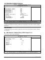
2.2 Standard CMOS Features.............................................................. 2-4
2.3 Advanced BIOS Features .............................................................. 2-7
2.4 Advanced Chipset Features........................................................... 2-9
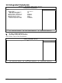
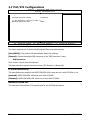
2.5 Integrated Peripherals................................................................ 2-10
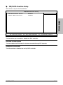
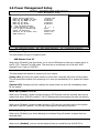
2.6 Power Management Setup .......................................................... 2-14
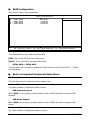
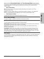
2.7 PnP/PCI Configurations .............................................................. 2-16
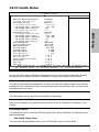
2.8 PC Health Status ........................................................................ 2-17
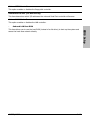
2.9 Load Fail-Safe Defaults............................................................... 2-19
2.10 Load Optimized Defaults........................................................... 2-19
2.11 Set Password ........................................................................... 2-19
2.12 Save & Exit Setup..................................................................... 2-19
2.13 Exit Without Saving .................................................................. 2-19

iv AN52S/AN52
3. Driver & Utility ................................................................. 3-1
3.1 CD-ROM AUTORUN ...................................................................... 3-1
3.2 nVidia nForce Chipset Driver ......................................................... 3-2
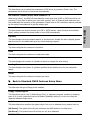
3.3 Realtek HD Audio Driver ............................................................... 3-2
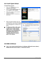
3.4 Cool’n’Quiet Driver ....................................................................... 3-4
3.5 USB 2.0 Driver ............................................................................. 3-4
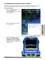
3.6 abitEQ (The Hardware Doctor Utility) ............................................ 3-5
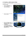
3.7 FlashMenu (BIOS Update Utility) ................................................... 3-6
3.8 SATA RAID Driver (for Windows Vista) .......................................... 3-7
3.9 SATA RAID Driver (for Windows XP, 2003, or 2000)....................... 3-7
4. Multilingual Quick Installation Guide .............................. 4-1
4.1 Français//Guide d'Installation Rapide............................................. 4-1
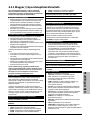
4.2 Deutsch//Kurze Installationsanleitung............................................ 4-2
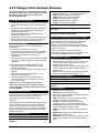
4.3 Italiano//Guida all’installazione rapida ........................................... 4-3
4.4 Español//Guía rápida de instalación............................................... 4-4
4.5 Português//Guia de instalação rápida ............................................ 4-5
4.6 Русский//Краткое руководство по установке .............................. 4-6
4.7 Eesti//Kiirpaigaldusjuhend ............................................................ 4-7
4.8 Latviski//Ātrās instalēšanas instrukcija........................................... 4-8
4.9 Lietuvių//Trumpas instaliavimo vadovas ........................................ 4-9
4.10 Polski//Instrukcja szybkiej instalacji........................................... 4-10
4.11 Magyar//Gyorstelepítési útmutató.............................................. 4-11
4.12 Türkçe//Hızlı Kurulum Kılavuzu.................................................. 4-12
4.13 اللغة العربية//دليل التركيب السريع....................... 4-13
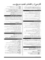
4.14 فارسی// راﻩنمای نصب سریع............................................... 4-14
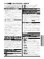
4.15 日本語//クイックインストールガイド ...................................... 4-15
4.16 한국어//빠른 설치 가이드 ....................................................... 4-16
4.17 Bahasa Malaysia//Panduan Pemasangan Ringkas ....................... 4-17
4.18 ไทย//คู่มือการติดตั้งอย่างย่อ ........................................................ 4-18
4.19 繁體中文................................................................................. 4-19
4.19.1 規格............................................................................... 4-19
4.19.2 快速安裝略說.................................................................. 4-20
4.20 简体中文................................................................................. 4-21
4.20.1 规格 ............................................................................... 4-21
4.20.2 快速安装略说.................................................................. 4-22
5. Appendix .......................................................................... 5-1
5.1 Troubleshooting (How to Get Technical Support?).......................... 5-1
5.1.1 Q & A ................................................................................. 5-1
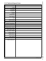
5.1.2 Technical Support Form....................................................... 5-4
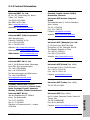
5.1.3 Contact Information............................................................. 5-5

Hardware Setup
AN52S/AN52 1-1
1. Hardware Setup
1.1 Specifications
CPU
• Supports Socket AM2 940 Processor
with 2000MT/s system bus using Hyper
Transport™ Technology
• Supports AMD CPU Cool ‘n’ Quiet
Technology
Chipset
• NVIDIA NF520 Single Chip
Memory
• 4x 240-pin DIMM slots support
maximum memory capacity up to 8GB
• Supports Dual Channel DDR2 800
Un-buffered ECC/Non-ECC memory
LAN
• Onboard Gigabit LAN
Audio
• Onboard 7.1-Channel HD Audio CODEC
• Supports auto Jack Sensing and Jack
Retasking functions
Serial ATA
• 4x SATA 3Gb/s supports SATA RAID 0,
1, 0+1, 5
Expansion Slots
• 1x PCI-E X16 slot
• 2x PCI-E X1 slots
• 3x PCI slots
Internal I/O Connectors
• 1x Floppy port
• 1x Ultra ATA 133 IDE connector
• 4x SATA 3Gb/s connectors
• 3x USB 2.0 headers
• 1x FP-Audio header
• 1x CD-In connector
Rear Panel I/O
• 1x PS/2 Keyboard connector
• 1x PS/2 Mouse connector
• 1x COM port
(For AN52S only)
• 1x External CMOS Clearing Switch
(For
AN52S only)
• 1x 7.1-Channel Audio connector
• 4x USB 2.0 connectors
• 1x RJ-45 LAN connector
abit Engineered
• abit Softmenu
™
Technology
• abit Silent OTES
™
Technology
(For
AN52S only)
• External CMOS Clearing Switch
(For
AN52S only)
RoHS
• 100% Lead-free process and RoHS
compliant
Miscellaneous
• ATX form factor (305mm x 245mm)
• Vista HW Ready
※ Specifications and information contained herein are subject to change without
notice.

1-2 AN52S/AN52
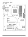
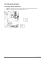
1.2 Motherboard Layout
1.2.1 AN52S

Hardware Setup
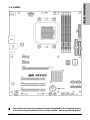
AN52S/AN52 1-3
1.2.2 AN52
※ The motherboard and its component layouts illustrated in the following chapter
of this manual were mainly based on model “AN52S”, unless specifically stated.

1-4 AN52S/AN52
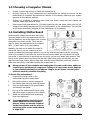
1.3 Choosing a Computer Chassis
• Choose a chassis big enough to install this motherboard.
• As some features for this motherboard are implemented by cabling connectors on the
motherboard to indicators and switches or buttons on the chassis, make sure your chassis
supports all the features required.
• If there is a possibility of adopting some more hard drives, make sure your chassis has
sufficient power and space for them.
• Most chassis have alternatives for I/O shield located at the rear panel. Make sure the I/O
shield of the chassis matches the I/O port configuration of this motherboard. You can find
an I/O shield specifically designed for this motherboard in its package.
1.4 Installing Motherboard
Most computer chassis have a base with many
mounting holes to allow the motherboard to be
securely attached, and at the same time, prevent
the system from short circuits. There are two
ways to attach the motherboard to the chassis
base: (1) with studs, or (2) with spacers.
Basically, the best way to attach the board is
with studs. Only if you are unable to do this
should you attach the board with spacers. Line up the holes on the board with the mounting
holes on the chassis. If the holes line up and there are screw holes, you can attach the board
with studs. If the holes line up and there are only slots, you can only attach with spacers. Take
the tip of the spacers and insert them into the slots. After doing this to all the slots, you can
slide the board into position aligned with slots. After the board has been positioned, check to
make sure everything is OK before putting the chassis back on.
※ Always power off the computer and unplug the AC power cord before adding or
removing any peripheral or component. Failing to so may cause severe damage
to your motherboard and/or peripherals. Plug in the AC power cord only after
you have carefully checked everything.
To install this motherboard:
1. Locate all the screw holes on the
motherboard and the chassis base.
2. Place all the studs or spacers needed on
the chassis base and have them tightened.
3. Face the motherboard’s I/O ports toward
the chassis’s rear panel.
4. Line up all the motherboard’s screw holes
with those studs or spacers on the chassis.
5. Install the motherboard with screws and
have them tightened.
※ To prevent shorting the PCB circuit,
please REMOVE the metal studs or
spacers if they are already fastened
on the chassis base and are without
mounting-holes on the motherboard
to align with.
Face the chassis’s rear panel.

Hardware Setup
AN52S/AN52 1-5
1.5 Checking Jumper Settings
• For a 2-pin jumper, plug the
jumper cap on both pins will
make it CLOSE (SHORT).
Remove the jumper cap, or
plug it on either pin
(reserved for future use) will
leave it at OPEN position.
SHORT OPEN
OPEN
• For 3-pin jumper, pin 1~2 or pin 2~3 can be
shorted by plugging the jumper cap in.
Pin 1~2 SHORT
Pin 2~3 SHORT
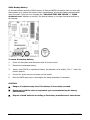
1.5.1 CMOS Memory Clearing Header and Backup Battery
The time to clear the CMOS memory occurs when (a)
the CMOS data becomes corrupted, (b) you forgot the
supervisor or user password preset in the BIOS menu,
(c) you are unable to boot-up the system because the
CPU ratio/clock was incorrectly set in the BIOS menu,
or (d) whenever there is modification on the CPU or
memory modules.
This header uses a jumper cap to clear the CMOS
memory and have it reconfigured to the default values
stored in BIOS.
• Pins 1 and 2 shorted
(Default): Normal
operation.
• Pins 2 and 3 shorted:
Clear CMOS memory.
To clear the CMOS memory and load in the default values:
1. Power off the system.
2. Set pin 2 and pin 3 shorted by the jumper cap. Wait for a few seconds. Set the jumper
cap back to its default settings --- pin 1 and pin 2 shorted.
3. Power on the system.
4. For incorrect CPU ratio/clock settings in the BIOS, press <Del> key to enter the BIOS
setup menu right after powering on system.
5. Set the CPU operating speed back to its default or an appropriate value.
6. Save and exit the BIOS setup menu.
※ Another easy way to clear the CMOS memory can be done by switching the
“EZ-CCMOS1”, see the section of “Connecting Rear Panel I/O Devices” in this
manual for detail.
(For AN52S only)
※ Please do shut down the system power before clearing CMOS memory.

1-6 AN52S/AN52
CMOS Backup Battery:
An onboard battery saves the CMOS memory to keep the BIOS information stays on even after
disconnected your system with power source. Nevertheless, this backup battery exhausts after
some five years. Once the error message like “CMOS BATTERY HAS FAILED” or “CMOS
checksum error” displays on monitor, this backup battery is no longer functional and has to
be renewed.
To renew the backup battery:
1. Power off the system and disconnect with AC power source.
2. Remove the exhausted battery.
3. Insert a new CR2032 or equivalent battery. Pay attention to its polarity. The “+” side is its
positive polarity.
4. Connect AC power source and power on the system.
5. Enter the BIOS setup menu. Reconfigure the setup parameters if necessary.
CAUTION:
※ Danger of explosion may arise if the battery is incorrectly renewed.
※ Renew only with the same or equivalent type recommended by the battery
manufacturer.
※ Dispose of used batteries according to the battery manufacturer’s instructions.

Hardware Setup
AN52S/AN52 1-7
1.6 Connecting Chassis Components
1.6.1 ATX Power Connectors
For a fully configured system, we recommend that
you use a power supply of ATX12V 2.0 (or newer)
specification compliant and of providing minimum
400W power output capability.
※ The following motherboard photos are
served for DEMO only, and may not be
the same type or model as the one
described in this user’s manual.
[ATXPWR1]: 24-pin power connector
You may connect either a 20-pin (ATX12V
1.3) or 24-pin (ATX12V 2.0) power source.
However, it is recommended to connect the
24-pin ATX12V power source to meet the
240VA protection limits.
Plugged from a 24-pin
ATX12V power.
Plugged from a 20-pin
ATX12V power.
[ATX12V1]: 8-pin power connector
This connector supplies +12V power to CPU.
You may connect either a 4-pin ATX12V or
an 8-pin EPS12V power source. However, it
is recommended to connect the 8-pin
EPS12V power source to meet the 240VA
protection limits.
Plugged from a 4-pin
ATX12V power.
Plugged from an 8-pin
EPS12V power.

1-8 AN52S/AN52
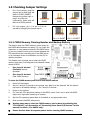
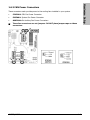
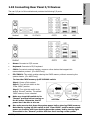
1.6.2 Front Panel Switches & Indicators Headers
This header is used for connecting switches and LED indicators on the chassis front panel.
Watch the power LED pin position and orientation. The mark “+” align to the pin in the figure
below stands for positive polarity for the LED connection. Please pay attention when connecting
these headers. A wrong orientation will only result in the LED not lighting, but a wrong
connection of the switches could cause system malfunction.
• HLED (Pin 1, 3):
Connects to the HDD LED cable of chassis front panel.
• RST (Pin 5, 7):
Connects to the Reset Switch cable of chassis front panel.
• SPKR (Pin 13, 15, 17, 19):
Connects to the System Speaker cable of chassis.
• SLED (Pin 2, 4):
Connects to the Suspend LED cable (if there is one) of chassis front panel.
• PWR (Pin 6, 8):
Connects to the Power Switch cable of chassis front panel.
• PLED (Pin 16, 18, 20):
Connects to the Power LED cable of chassis front panel.

Hardware Setup
AN52S/AN52 1-9
1.6.3 FAN Power Connectors
These connectors each provide power to the cooling fans installed in your system.
• CPUFAN1: CPU Fan Power Connector
• SYSFAN1: System Fan Power Connector
• AUXFAN1~2: Auxiliary Fan Power Connectors
※ These fan connectors are not jumpers. DO NOT place jumper caps on these
connectors.

1-10 AN52S/AN52
1.7 Installing Hardware
※ DO NOT scratch the motherboard when installing hardware. An accidentally
scratch of a tiny surface-mount component may seriously damage the
motherboard.
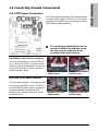
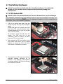
1.7.1 CPU Socket AM2
※ DO NOT touch or bend the delicate pins on the CPU whenever you are holding it.
The installation procedures vary with different types of CPU fan-and-heatsink assembly. The
one shown here is served for DEMO only. For detailed information on how to install the one
you bought, refer to its installation guidelines.
1. Pull out the socket lever away from the
socket and fully lift it up over 90-degree
angle.
Locate and align the triangle mark with
both the CPU and the socket body.
Vertically place the CPU with its pin-side
down into the socket.
Be careful to insert the CPU into the
socket. The CPU only fits in one
orientation with the socket. DO NOT
force the CPU into the socket.
2. After placing the CPU into position, push
the socket lever down into its locked
position to secure the CPU. The lever
clicks when it’s locked into position.
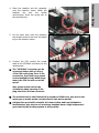
3. The heatsink for CPU may have thermal
interface material attached to its
bottom. If not, applying a few squeeze
of thermal paste to the CPU die will help
to increase the contact.

Hardware Setup
AN52S/AN52 1-11
4. Place the heatsink and fan assembly
onto the retention frame. Match the
heatsink clip with the socket
mounting-lug. Hook the spring clip to
the mounting-lug.
5. On the other side, push the retention
clip straight down to lock into the plastic
lug on the retention frame.
6. Connect the CPU cooling fan power
cable to the CPUFAN1 connector on this
motherboard.
※ The “CPUFAN1” connector can be
connected either with a 3-Pin or
4-Pin CPU cooling fan. For a 3-Pin
connection, there will be no speed
control available in the BIOS setup
menu; the CPU fan will run at full
speed.
Also, please watch out for the
orientation when inserting 3-Pin
plug into this 4-Pin fan connector.
※ The motherboard in this illustration is served for DEMO only, may not be the
same type or model as the one described in this user’s manual.
※ A higher fan speed will be helpful for better airflow and heat-dissipation.
Nevertheless, stay alert to not touch any heatsink since a high temperature
generated by the working system is still possible.

1-12 AN52S/AN52
1.7.2 DDR2 Memory Slots
To reach the performance of Dual Channel DDR2, the following rules must be obeyed:
• For a 2-DIMM dual-channel installation:
Populate DIMM modules of the same type and size on slots [DIMM1]+[DIMM2], or slots
[DIMM3]+[DIMM4].
• For a 4-DIMM dual-channel installation:
Populate 2 DIMM modules of the same type and size on slots [DIMM1]+[DIMM2], and
another 2 DIMM modules of the same type and size on slots [DIMM3]+[DIMM4].
※ [DIMM1] and [DIMM2] slots are made of the same color.
[DIMM3] and [DIMM4] are made of another same color.
Usually there is no hardware or BIOS setup requires after adding or removing memory modules,
but you will have to clear the CMOS memory first if any memory module related problem
occurs.
To install system memory:
1. Power off the computer and unplug the
AC power cord before installing or
removing memory modules.
2. Locate the DIMM slot on the board.
3. Hold two edges of the DIMM module
carefully, keep away from touching its
connectors.
4. Align the notch key on the module with the rib on the slot.
5. Firmly press the module into the slots until the ejector tabs at both sides of the slot
automatically snap into the mounting notch. Do not force the DIMM module in with extra
force as the DIMM module only fits in one direction.
6. To remove the DIMM modules, push the two ejector tabs on the slot outward
simultaneously, and then pull out the DIMM module.
※ Static electricity can damage the electronic components of the computer or
optional boards. Before starting these procedures, ensure that you are
discharged of static electricity by touching a grounded metal object briefly.

Hardware Setup
AN52S/AN52 1-13
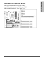
1.8 Connecting Peripheral Devices
1.8.1 Floppy and IDE Disk Drive Connectors
The FDC1 connector connects up to two floppy drives with a 34-wire, 2-connector floppy cable.
Connect the single end at the longer length of ribbon cable to the FDC1 on the board, the two
connectors on the other end to the floppy disk drives connector. Generally you need only one
floppy disk drive in your system.
※ The red line on the ribbon cable must be aligned with pin-1 on both the FDC1
port and the floppy connector.
Each of the IDE port connects up to two IDE drives
at Ultra ATA/100 mode by one 40-pin, 80-conductor,
and 3-connector Ultra ATA/66 ribbon cables.
Connect the sin
g
le end (blue connector) at the lon
g
er
length of ribbon cable to the IDE port of this board,
the other two ends (gray and black connector) at the
shorter length of the ribbon cable to the connectors
of your hard drives.
※ Make sure to configure the “Master” and “Slave” relation before connecting
two drives by one single ribbon cable. The red line on the ribbon cable must be
aligned with pin-1 on both the IDE port and the hard-drive connector.

1-14 AN52S/AN52
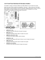
1.8.2 Serial ATA Connectors
Each SATA connector serves as one single channel to connect one SATA device by SATA cable.
To connect SATA device:
1. Attach either end of the signal cable
to the SATA connector on
motherboard. Attach the other end to
the SATA device.
2. Attach the SATA power cable to the
SATA device and connect the other
end from the power supply.
※ The motherboard in this photo is served for DEMO only, and may not be the
same type or model as the one described in this user’s manual.
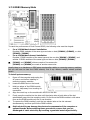
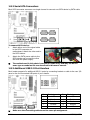
1.8.3 Additional USB 2.0 Port Headers
Each header supports 2x additional USB 2.0 ports by connecting bracket or cable to the rear I/O
panel or the front-mounted USB ports of your chassis.
Pin Pin Assignment Pin Pin Assignment
1 VCC 2 VCC
3 Data0 - 4 Data1 -
5 Data0 + 6 Data1 +
7 Ground 8 Ground
10 NC
※ Make sure the connecting cable bears the same pin assignment.

Hardware Setup
AN52S/AN52 1-15
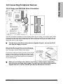
1.8.4 Internal Audio Connectors
This connector connects to the audio output of internal CD-ROM drive or add-on card.
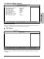
1.8.5 Front Panel Audio Connection Header
This header provides the front panel connection for HD (High Definition)
Audio, yet for AC’97 Audio CODEC connection, you must carefully check the
pin assignment before connecting from the front panel module. An incorrect
connection may cause malfunction or even damage the motherboard.
※ Please do not connect the “Ground” cable or “USB VCC” cable
from the front panel module to the Pin 4 “AVCC” of this
header.
Pin
Pin Assignment
(HD AUDIO)
Pin
Pin Assignment
(AC’97 AUDIO)
1 MIC2 L 1 MIC In
2 AGND 2 GND
3 MIC2 R 3 MIC Power
4 AVCC 4NC
5 FRO-R 5 Line Out (R)
6 MIC2_JD 6 NC
7F_IO_SEN 7 NC
9 FRO-L 9 Line Out (L)
10 LINE2_JD 10 NC

1-16 AN52S/AN52
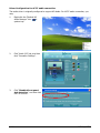
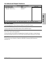
Driver Configuration for AC’97 audio connection:
The audio driver is originally configured to support HD Audio. For AC’97 audio connection, you
may:
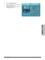
1. Right-click the “Realtek HD
Audio Manager” icon
in
system tray.
2. Click “Audio I/O” tab, and then
click “Connector Settings”.
3. Click “Disabled front panel
jack detection”, and then click
“OK” to confirm.
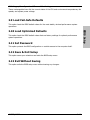
La pagina si sta caricando...
La pagina si sta caricando...
La pagina si sta caricando...
La pagina si sta caricando...
La pagina si sta caricando...
La pagina si sta caricando...
La pagina si sta caricando...
La pagina si sta caricando...
La pagina si sta caricando...
La pagina si sta caricando...
La pagina si sta caricando...
La pagina si sta caricando...
La pagina si sta caricando...
La pagina si sta caricando...
La pagina si sta caricando...
La pagina si sta caricando...
La pagina si sta caricando...
La pagina si sta caricando...
La pagina si sta caricando...
La pagina si sta caricando...
La pagina si sta caricando...
La pagina si sta caricando...
La pagina si sta caricando...
La pagina si sta caricando...
La pagina si sta caricando...
La pagina si sta caricando...
La pagina si sta caricando...
La pagina si sta caricando...
La pagina si sta caricando...
La pagina si sta caricando...
La pagina si sta caricando...
La pagina si sta caricando...
La pagina si sta caricando...
La pagina si sta caricando...
La pagina si sta caricando...
La pagina si sta caricando...
La pagina si sta caricando...
La pagina si sta caricando...
La pagina si sta caricando...
La pagina si sta caricando...
La pagina si sta caricando...
La pagina si sta caricando...
La pagina si sta caricando...
La pagina si sta caricando...
La pagina si sta caricando...
La pagina si sta caricando...
La pagina si sta caricando...
La pagina si sta caricando...
La pagina si sta caricando...
La pagina si sta caricando...
La pagina si sta caricando...
La pagina si sta caricando...
La pagina si sta caricando...
La pagina si sta caricando...
La pagina si sta caricando...
La pagina si sta caricando...
La pagina si sta caricando...
La pagina si sta caricando...
La pagina si sta caricando...
La pagina si sta caricando...
-
 1
1
-
 2
2
-
 3
3
-
 4
4
-
 5
5
-
 6
6
-
 7
7
-
 8
8
-
 9
9
-
 10
10
-
 11
11
-
 12
12
-
 13
13
-
 14
14
-
 15
15
-
 16
16
-
 17
17
-
 18
18
-
 19
19
-
 20
20
-
 21
21
-
 22
22
-
 23
23
-
 24
24
-
 25
25
-
 26
26
-
 27
27
-
 28
28
-
 29
29
-
 30
30
-
 31
31
-
 32
32
-
 33
33
-
 34
34
-
 35
35
-
 36
36
-
 37
37
-
 38
38
-
 39
39
-
 40
40
-
 41
41
-
 42
42
-
 43
43
-
 44
44
-
 45
45
-
 46
46
-
 47
47
-
 48
48
-
 49
49
-
 50
50
-
 51
51
-
 52
52
-
 53
53
-
 54
54
-
 55
55
-
 56
56
-
 57
57
-
 58
58
-
 59
59
-
 60
60
-
 61
61
-
 62
62
-
 63
63
-
 64
64
-
 65
65
-
 66
66
-
 67
67
-
 68
68
-
 69
69
-
 70
70
-
 71
71
-
 72
72
-
 73
73
-
 74
74
-
 75
75
-
 76
76
-
 77
77
-
 78
78
-
 79
79
-
 80
80


Abit AN52 Manuale del proprietario
- Categoria
- Schede madri
- Tipo
- Manuale del proprietario
in altre lingue
- English: Abit AN52 Owner's manual
Documenti correlati
-
Abit Fatal1ty FP-IN9 SLI Manuale utente
-
-
-
-
Abit IP35 PRO XE Manuale utente
-
-
-
Abit IP35 Manuale del proprietario
-