
1
Once your PHILIPS purchase is registered, you’re eligible to receive all the privileges of owning a
PHILIPS product. So complete and return the Warranty Registration Card enclosed with your
purchase at once, and take advantage of these important benefits.
Return your Warranty Registration card today to ensure
you receive all the
benefits
you’re entitled to.
For Customer Use
Enter below the Serial No., which is
located on the rear of the cabinet. Retain
this information for future reference.
Model No. __________________________
Serial No. __________________________
Congratulations on your purchase, and
welcome to the “family!”
Dear PHILIPS product owner:
Thank you for your confidence in PHILIPS.You’ve selected one of
the best-built, best-backed products available today.And we’ll do
everything in our power to keep you happy with your
purchase for many years to come.
As a member of the PHILIPS “family,” you’re entitled to
protection by one of the most comprehensive warranties and
outstanding service networks in the industry.
What’s more, your purchase guarantees you’ll receive all the
information and special offers for which you qualify, plus easy
access to accessories from our convenient home shopping
network.
And most importantly you can count on our uncompromising
commitment to your total satisfaction.
All of this is our way of saying welcome-and thanks for investing
in a PHILIPS product.
Sincerely,
Lawrence J. Blanford
President and Chief Executive Officer
P.S. Remember, to get the most from your PHILIPS
product, you must return your Warranty
Registration Card within 10 days. So please mail
it to us right now!
Know these
safety symbols
This “bolt of lightning” indicates
uninsulated material within your unit
may cause an electrical shock. For the
safety of everyone in your household, please
do not remove product
covering.
The “exclamation point” calls attention
to features for which you should read
the enclosed literature closely to
prevent operating and maintenance
problems.
WARNING: TO PREVENT FIRE OR
SHOCK HAZARD, DO NOT EXPOSE THIS
EQUIPMENT TO RAIN OR MOISTURE.
CAUTION: To prevent electric shock,
match wide blade of plug to wide slot, fully
insert.
ATTENTION:Pour éviter les choc
électriques, introduire la lame la plus large de
la fiche dans la borne correspondante de la
prise et pousser jusqu’au fond.
CAUTION
RISK OF ELECTRIC SHOCK
DO NOT OPEN
CAUTION: TO REDUCE THE RISK OF ELECTRIC SHOCK, DO NOT
REMOVE COVER (OR BACK). NO USER-SERVICEABLE PARTS
INSIDE. REFER SERVICING TO QUALIFIED SERVICE PERSONNEL.
R
E
G
I
S
T
R
A
T
I
O
N
N
E
E
D
E
D
W
I
T
H
I
N
1
0
D
A
Y
S
Hurry!
Warranty
Verification
Registering your product within
10 days confirms your right to
maximum protection under the
terms and conditions of your
PHILIPS warranty.
Owner
Confirmation
Your completed Warranty
Registration Card serves as
verification of ownership in the
event of product theft or loss.
Model
Registration
Returning your Warranty Registration
Card right away guarantees you’ll
receive all the information and special
offers which you qualify for as the
owner of your model.
Visit our World Wide Web Site at http://www.philips.com
t
s
EnglishFrançaisEspañol
2268.1 am 03-12-2003 09:47 Pagina 1

2
1. Read these instructions.
2. Keep these instructions.
3. Heed all warnings.
4. Follow all instructions.
5. Do not use this apparatus near water.
6. Clean only with a dry cloth.
7. Do not block any of the ventilation openings. Install in
accordance with the manufacturers instructions.
8. Do not install near any heat sources such as radiators, heat
registers, stoves, or other apparatus (including amplifiers)
that produce heat.
9. Do not defeat the safety purpose of the polarized or
grounding-type plug. A polarized plug has two blades with
one wider than the other. A grounding type plug has two
blades and third grounding prong.The wide blade or third
prong are provided for your safety.When the provided plug
does not fit into your outlet, consult an electrician for
replacement of the obsolete outlet.
10. Protect the power cord from being walked on or pinched
particularly at plugs, convenience receptacles, and the point
where they exit from the apparatus.
11. Only use attachments/accessories specified by the
manufacturer.
12. Use only with a cart, stand, tripod, bracket, or
table specified by the manufacturer, or sold with
the apparatus.When a cart is used, use caution
when moving the cart/apparatus combination to avoid injury
from tip-over.
13. Unplug this apparatus during lightning storms or when
unused for long periods of time.
14. Refer all servicing to qualified service personnel. Servicing is
required when the apparatus has been damaged in any way,
such as power-supply cord or plug is damaged, liquid has
been spilled or objects have fallen into apparatus, the
apparatus has been exposed to rain or moisture, does not
operate normally, or has been dropped.
15. This product may contain lead or mercury. Disposal of these
materials may be regulated due to environmental
considerations. For disposal or recycling information, please
contact your local authorities or the Electronic Industries
Alliance: www.eiae.org.
16. Damage Requiring Service - The appliance should be
serviced by qualified service personnel when:
A. The power supply cord or the plug has been damaged;
or
B. Objects have fallen, or liquid has been spilled into the
appliance; or
C. The appliance has been exposed to rain; or
D. The appliance does not appear to operate normally or
exhibits a marked change in performance; or
E. The appliance has been dropped, or the enclosure
damaged.
17. Tilt/Stability - All televisions must comply with
recommended international global safety standards for tilt
and stability properties of its cabinets design.
• Do not compromise these design standards by applying
excessive pull force to the front, or top, of the cabinet
which could ultimately overturn the product.
• Also, do not endanger yourself, or children, by placing
electronic equipment/toys on the top of the cabinet.
Such items could unsuspectingly fall from the top of
the set and cause product damage and/or personal
injury.
18. Wall Mounting - The appliance should be mounted to a
wall only as recommended by the manufacturer.
19. Power Lines - An outdoor antenna should be located away
from power lines.
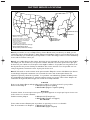
20. Outdoor Antenna Grounding - If an outside antenna is
connected to the receiver, be sure the antenna system is
grounded so as to provide some protection against voltage
surges and built up static charges.
Section 810 of the National Electric Code, ANSI/NFPA No.
70-1984, provides information with respect to proper
grounding of the mats and supporting structure grounding
of the lead-in wire to an antenna-discharge unit, size of
grounding connectors, location of antenna-discharge unit,
connection to grounding electrodes and requirements for
the grounding electrode. See Figure below.
21. Objects and Liquid Entry - Care should be taken so that
objects do not fall and liquids are not spilled into the
enclosure through openings.
IMPORTANT SAFETY INSTRUCTIONS
Read before operating equipment
Congratulations on purchasing this Philips product.
We’ve included everything you need to get started.
If you have any problems, Philips reprensatives can
help you get the most from your new product by explaining:
• Hookups
• First Time Setup, and
• Feature Operation.
For fast help, call us first !
1-800-531-0039
Thank you for making Philips a part of your home!
2268.1 am 03-12-2003 09:47 Pagina 2

3
This symbol informs that there are contents that demand caution (including warnings).
This symbol indicates a prohibited matter.
This symbol indicates something that must be done.
WARNING
When installing the plasma display or making angle adjustments, be sure to make a request for service
with the dealer and ensure the work is performed according to this manual. Incorrect installation and
angle adjustments may result in the plasma display falling and causing injury.
To prevent the plasma display from falling, the strength of the installation place and the method of
fastening must support the combined weight of the plasma display and the mounting unit for an
extended period of time as well as withstand earthquakes. Improper installation may result in the plasma
display falling and causing injury. Be sure to observe the following matters.
- An electrical outlet should be used for the power supply of the plasma display. Direct connection to a
power cable is dangerous and should not be used. Please use a power outlet that can be reached to
allow the insertion and withdrawal of the power plug.
- Installation for Wooden Walls:The load should by all means be carried by beams, and when the
strength of the beams is insufficient, they should be strengthened.The installation should not be made
to skirting or supporting members. The load should also be carried by beams when there is a steel
beam suspended ceiling; installation should not be made to the ceiling suspension fittings.
- Installation for Concrete Walls: Commercial anchors that are strong enough to easily support the load
of the plasma display should be used.
- Not for use in a computer room as defined in the Standard for the Protection of Electronic
Computer/Data Processing Equipment ANSI/NFPA 75.
To ensure safety, bolts and screws must be tightened securely. Be sure to use the supplied parts for the
brackets and the other fittings. Failure to do so may result in the plasma display falling and causing injury.
When aligning the grooves of the display fittings to the fixed unit, check to make sure that they are
securely engaged. Failure to do so may result in the plasma display falling and causing injury.
Do not modify any parts. Failure to do so may result in the plasma display falling and causing injury.
Do not use any damaged parts. Failure to do so may result in the plasma display falling and causing
injury. In the event that any parts are damaged, please contact the dealer.
This plasma display mounting unit is for use only with PHILIPS 50 inch plasma displays. Do not use with
any other equipment since the equipment could fall and cause injury.
WARNING
Do not obstruct the ventilation holes of the plasma display. Doing so will prevent the dissipation of heat
and may result a fire. Do not use the plasma display in the following ways:
Do not install the plasma display in a tight place where ventilation is poor, place a cover on it, etc.
Do not install the plasma display in front of the vents of an air conditioner or heater, or in a place
where there is strong vibration. Doing so may result in fire or electrical shock.
Do not install the plasma display in humid or dusty places, or where it will be exposed to greasy smoke
or steam (such as near cooking equipment or humidifiers). Doing so may result in a fire. Do not use the
plasma display outdoors. Doing so may result in a fire or electrical shock.
The plasma display shall not be exposed to dripping or splashing and no objects filled with liquids, such
as vases, shall be placed on it.
Leave sufficient space around the plasma display when installing it.
Failure to do so may load to head buildup within the display and could result in fire.
Hold the plasma display in place while attaching it to the unit. Failing to do so may lead to it falling and
causing injury.
Installation Location
Avoid rooms with a lot of dust, humidity, greasy smoke, or tobacco smoke.
Dirt will adhere to the surface of the display monitor screen and cause a deterioration in image quality.
Avoid places in which the screen is exposed to direct sunlight or illumination light.
When surrounding light hits the screen directly, the image appears washed out and is difficult to view.
Avoid places which reach high temperatures or low temperatures.
Such extreme temperatures will cause breakdown.
Ignoring this indication and improper handling could be the
cause of personal injury such as a serious injury or death.
Ignoring this indication and improper handling could cause injury
to a person or damage to the surrounding household belongings.
2268.1 am 03-12-2003 09:47 Pagina 3

4
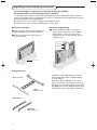
Unpacking and wall mounting instructions
Special technology is required in the mounting of the plasma display.
Such work should never be undertaken by the customer.
For the safety of the customer, we ask that the installation work be started after careful attention is
paid to the strength of the mounting location to be sure it will withstand the weight (about 97 Lbs) of
the plasma display and mounting hardware.
Be sure that two or more persons engage in the installation work.
Be careful not to lose any of the removed screws or other parts.
Remove the packaging
& Open the upper carton which packages the
plasma display and remove the styrofoam.
é Remove the upper carton and open the
protective sheet.
Package parts list
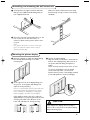
Attach the display fittings
“ With the display standing in its packaging
carton, align the square holes of the display
fittings with the screw holes of the plasma
display, then fasten the display fittings using the
supplied screws.
Installation of the display fittings can also be
performed by laying down the plasma display
on a flat surface.
Remove the plasma display form the carton,
place the protective sheet that was used in the
packaging on a flat surface (which is larger than
the display), then lay the display down on top of
this with the screen surface facing downward.
Protective sheet
M4 screws x 4
M4 screws x 8
round hole
square hole
display fittings
wall mount unit
2268.1 am 03-12-2003 09:47 Pagina 4

5
Assembling and mounting the wall mount unit
& Securely fasten the upper and lower wall-side
fittings to the middle wall-side fitting with the
four supplied M4 screws.
é Fasten the unit with commercial anchors or the
four screws. Be sure that the anchors or
screws are fastened at a position where there
is a post.
Note:
Use anchors and screws to suit the various wall
types.The enclosed template can be used for
general positioning only.
Make sure that the wall mount unit is being
fixed securely enough so that it meets safety
standards.
5
Mounting the plasma display
& Mount the display (to which the display fittings
have already been attached) to the wall
mounting unit.
é Fit the upper hooks of the display fittings into
the grooves of the (upper) wall fittings and
adjust for level positioning.
Note: It is recommended that the power cable and
various signal cables be plugged into the display
before mounting the display. After mounting the
display, plugging in the cables may be difficult.
If the display is tilted to the left or right, the
display fitting is not properly placed on the wall
mounting unit. Slide in the direction of the
lower side and adjust for level positioning.
“ Anchor the plasma display.
Align the thumb screw, which is located at the
bottom of the display fitting, with the hole of
the (lower) wall-side fitting and tighten to
anchor.
Fasten securely until the screw ceases to turn.
To r emove the display, loosen the thumb
screws until they come out of the hole.
Pull the bottom portion of the display towards
you and lift upward to release the display.
CAUTION
Firmly support the display when mounting it.
Failure to do so may result in the plasma display
falling and causing injury.
2268.1 am 03-12-2003 09:47 Pagina 5

CVBS 1
CVBS 2
Y/C
VGA
R/Cr/Pr
Y
Cb/Pb
Cr/Pr
DVD/HD
RGB/DVD/HD
EXTERNAL
CONTROL
G/Y
B/Cb/Pb
HD
DVI
VD
6
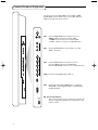
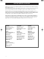
You may connect 2 possible VGA sources (VGA or RGB
Digital (DVI)) and 3 possible video sources (AV1,AV2 and
AV3) to the right side of the monitor.
AV1 Connect VCRs, DVDs or Laser Discs, etc. here.
CVBS 1 : BNC connector for Video CVBS
or
CVBS 2 : cinch connector for Video CVBS
or
Y/C 3 : S-Video connector for Y/C-SVHS video.
AV2 Connect DVD, HD, DTV or Laser Discs, etc. with
YPbPr connectors.
AV3 Connect DVDs, HD or Laser Discs, etc. here.
Use the 5 BNC connectors for RGB input.
Use the R/PrG/YB/Pb connectors for component input.
VGA Input for analog RGB signal of PC, etc.
DVI Inputs a PC with a digital RGB signal or equipment
(STB, DVD,...) with a digital interface compliant with
the DVI standard.
RS 232c Serial I/O port
This connector allows you to control your monitor via
external equipment (e.g. PC) and a replacement of the
remote control
Connect Peripheral Equipment
2268.1 am 03-12-2003 09:47 Pagina 6

7
Connect your computer
Operation
Directly to the plasma display
& Connect one end of a VGA cable supplied to
the video card of the computer and the other
end to the
VGA (or to RGB Digital DVI in
case of a computer with a digital
RGB output)
connector at the right side of the monitor. Fix
the connectors firmly with the screws on the
plug. See Table of Signals Supported, p. 19.
é In case of a Multimedia computer, connect the
audio cable to the
AUDIO outputs of your
computer and to the
AUDIO inputs of an
additional audio receiver.
To an electronic receiver box
See the handbook of the receiver box.
& Connect one end of a VGA cable to the video
card of the computer and the other end to the
VGA IN connector at the rear side of the
receiver box. Fix the connectors firmly with the
screws on the plug.
é In case of a Multimedia computer, connect the
audio cable to the
AUDIO outputs of your
computer and to the
AUDIO VGA IN R (right)
and
L (left) inputs of the receiver box.
Note:When you connect a computer to this monitor, attach the supplied ferrite cores. If you do not do this, this
monitor will not comply with the mandatory CE or C-Tick standards.
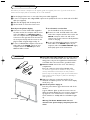
& Set the (large) ferrite core on one end of the power cable (supplied).
é In case of a computer with a digital RGB output set the (small) ferrite cores on both ends of the DVI
cable (not supplied).
“ Click the lids tightly until the clamps click.
‘ Use the bands to secure the ferrite cores.
R6 / AA
Power On/Off
Mains inlet
& Insert the mains plug supplied into the mains inlet at
the bottom of the monitor and in the wall socket. For
safety, please, only use the supplied rim-earthed mains
cord which has to be inserted in a grounded socket.
é Remote control:remove the cover of the battery
compartment.
In
sert the 2 batteries supplied (Type LR6/AA-1.5V).
The batteries supplied do not contain the heavy metals
mercury and cadmium. Nevertheless in many countries
batteries may not be disposed of with your household waste.
Please check on how to dispose of batteries according to
local regulations.
“ Make sure that your receiver box and/or PC are
switched on and that your PC is in the correct display
mode (see p. 19).
‘ Switch the plasma display on :
Press the power button B at the bottom side of the
monitor.
A green indicator lights up and the screen comes on.
When the plasma display does not receive a supported
vga signal or is not connected to a receiver box, the
screen switches to standby and the red indicator lights
up.
Warning:The Power On/Off switch does not
disconnect the plasma display completely from the
mains.
2268.1 am 03-12-2003 09:47 Pagina 7

8
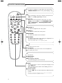
Use of the remote control
V
No function
¬ Mute button
No function
CH/PR Program selection
To browse through the sources selected.
AV MUTE
To m ute the picture or restore it if the plasma display is used
in the
VGA mode.
When activated a green indicator starts blinking in front of
the plasma display.
q Picture format
Press the
q button to switch between the different picture
formats.
Note: do not allow the displayed in 4:3 mode for an extended
period.This can cause a phosphor burn-in.
POWER
BRIGHTNESS
CONTRAST
ZOOM OUTZOOM INZOOM ON/OFF
VGA AV1 AV2 AV3
MUTE
AV MUTE
q
1
2
3
4
5
6
7
8
9
0
V
CH/PR
MENU
OK
¬
B
BRIGHTNESS +/-
To adjust the brightness level of the picture
CONTRAST +/-
To adjust the contrast level of the picture
ZOOM ON/OFF
To activate/de-activate the zoom function.
ZOOM IN/OUT
To adjust the zoom factor and to change the magnification of
the picture when zoom is activated.
Note: not possible with a 2.35:1 picture format.
VGA
Press repeatedly to select your computer connected to the
VGA or to the DVI (digital RGB) connector.
AV1,AV2,AV3
Press to select the peripherals connected to one of the
VIDEO connectors (AV1), to the COMPONENT INPUT
(AV2) (Y/CbPb/CrPr) or RCrPr/Gy/BCbPb/Hd/Vd
(
AV3) connectors.
B To s witch to standby or on again (Does not operate when
POWER/STANDBY indicator of the plasma display is off).
MENU
To s witch the menu on/off
Cursor buttons
To select your choice and to alter a selected adjustment.
OK To activate your choice
2268.1 am 03-12-2003 09:47 Pagina 8

9
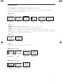
Picture format
Press the q button to switch between the different picture formats.
Note:When the setting of PICTURE SIZE in the OPTION2 menu, p. 14, is off, the picture format of RGB-input
pictures will be TRUE in place of NORMAL.
Video mode
In
Video mode:
•
Zoom: use this for theater size (wide) movies, etc.
•
Normal: this picture has the same size as video pictures with a 4:3 picture format
•
Stadium: use this for watching normal video programs (4:3) with a wide screen
•
14:9: this format is available when the input signal is video, component (4:3 signal) or RGB (480p or 576p signal)
•
2.35:1: this format is available when the input signal is video, component (480i, 480p, 576i, 576p, 720p, 1080i)
or RGB (525p or 625p signal from a scan converter).
HD mode
In
HD mode:
•
Full: the picture has the same size as video pictures (16:9).
VGA mode (4:3 signals)
VGA mode (wide signals)
Zoom Full
Full 2.35:1
14:9 Normal
Normal/True Full Zoom 2.35:1
2.35:1
True Full
Stadium
2.35:1
2268.1 am 03-12-2003 09:47 Pagina 9

10
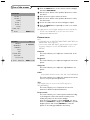
Use of the menus
& Press the MENU button on the remote control to display/
cancel the
MAIN MENU.
é Use the cursor button in the up/down directions to select
the menus.
“ Press the cursor right to access the menu.
‘ Use the cursor button in the up/down directions to select
the menu items.
( In case of a slider, move the cursor left/right to adjust.
§ Press the MENU button repeatedly to return or to switch
the menu off.
Note: Only when in the US English language has been selected (see
SET-UP menu, LANGUAGE, p. 16), the menu items will be
displayed with additional icons.
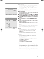
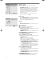
Picture menu
Note:
- In VGA mode only the CONTRAST, BRIGHTNESS, NOISE RED. and
COLOR TEMP. can be adjusted.
- If the message “CAN NOT ADJUST” appears when trying to adjust
the picture settings, be sure the PICTURE MODE is not set to
DEFAULT.
Contrast
This control allows you to adjust the contrast level of the
picture.
Brightness
This control allows you to adjust the brightness level of the
picture.
Sharpness
This control allows you to adjust the edge definition of a
picture.
Color
(only available when the source is AV1, AV2 or AV3 Y/CbPb/CrPr)
This control allows you to adjust the saturation level of the
colors to suit your personal preference.
Tint
(only available when the source is AV1 (NTSC only) AV2 or
AV3 (Y/CbPb/CrPr))
This control allows you to compensate for the color
variations in NTSC encoded transmissions.
Picture mode
This control allows you to select a picture mode according
to the brightness of the environment in which you are
viewing the pictures on the monitor display.
Press the cursor left/right to select
THEATRE 1 or 2 in a
dark room,
NORMAL in a bright room, BRIGHT to provide
brighter pictures than normal,
DEFAULT to reset the
picture to the settings predefined in the factory.
PICTURE 1
PICTURE 2
SCREEN
OPTION 1
OPTION 2
SET-UP
SOURCE INFO.
MAIN MENU
CONTRAST
BRIGHTNESS
SHARPNESS
COLOR
TINT
PICTURE MODE
NOISE RED.
œ next page
PICTURE 1 1/2
J
SELECT
LM
ADJUST MENU RETURN
L M
MJ
SELECT MENU RETURN
2268.1 am 03-12-2003 09:47 Pagina 10

11
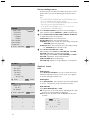
Noise reduction
This control allows you to reduce the noise in the picture
due to poor reception or poor picture quality.
Select
OFF, NR-1, NR-2 or NR-3 according to the level of
noise present.
Note: Select RESET in the OPTION 1 menu, p. 13, to restore the
predefined factory PICTURE settings.
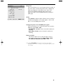
Color temperature
This control allows you to select the color temperature and
the white balance of the picture.
& Press the cursor left/right to select HIGH (bluer), MIDDLE
(standard), MIDDLE LOW (redder) or LOW (white balance).
é Select LOW to adjust the white balance for bright and dark
pictures.
“ Press the OK button to display the WHITE BALANCE
menu.
‘ Select and adjust Red-Green-Blue Gain to adjust the white
balance for signal level.
Select and adjust Red-Green-Blue
Bias to adjust the white
balance for black level.
Reset
This control allows you to reset the white balance settings
back to the predefined factory values and settings.
Gamma
This control allows you to adjust the brightness of the
midtone areas while keeping shadows and highlights
unchanged.
Select
1 to 4.
The picture becomes darker as the number increases;
Low tone
This control allows to reproduce more detailed tone
especially in the dark area.
Select
AUTO or 1 to 3.
•
AUTO will automatically upraise the picture and make
adjustments;
•
1 is suitable for still pictures;
•
2 for motion pictures;
•
3 will apply the error diffusion method.
Color tune
(This function can adjust video input and DVD/HD input only.)
This control allows you to adjust the hue and color density
for red, green, blue, yellow, magenta and cyan.
You can accentuate the green color of trees, the blue of the
sky, etc.
RESET resets the settings to the predefined factory values.
o previous page
COLOR TEMP.
GAMMA
LOW TONE
(COLOR TUNE)
PICTURE 2 2/2
OK
J
SELECT
LM
ADJUST MENU RETURN
L
MIDDLE
M
GAIN RED
GREEN
BLUE
BIAS RED
GREEN
BLUE
RESET
WHITE BALANCE
COLOR TEMP.
L M
J
SELECT
L M
ADJUST MENU RETURN
2268.1 am 03-12-2003 09:47 Pagina 11

12
Screen settings menu
In this menu you are allowed to adjust the position of the
picture and to correct the flickering of the picture menu
items.
Note:
- The AUTO PICTURE, FINE PICTURE and PICTURE ADJ. menu
items are available with PC signals (analog).
- The menu items FINE PICTURE and PICTURE ADJ. are available
only when you select AUTO PICTURE OFF.
- Select RESET in the OPTION 1 menu, p. 13, to restore the
predefined factory PICTURE settings.
& Select ASPECT MODE and press the cursor left/right to
select a picture format (
NORMAL or FULL in VGA-mode).
é Select V-POSITION, H-POSITION,V-HEIGHT, H-WIDTH
to adjust the position of the picture.
V-POSITION adjusts the vertical position,
H-POSITION adjusts the horizontal position,
V-HEIGHT adjusts the vertical size of the image (except for
STADIUM picture format mode),
H-WIDTH adjusts the horizontal size of the image (except
for
STADIUM picture format mode).
“ Select AUTO PICTURE ON or OFF.
When having selected
ON, the PICTURE ADJ. and FINE
PICTURE adjustments are made automatically.
When having selected
OFF, the PICTURE ADJ. and FINE
PICTURE adjustments can be made manually.
FINE PICTURE adjusts for flickering;
PICTURE ADJ. adjusts for striped patterns on the picture.
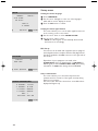
Option 1 menu
OSD
OSD DISPLAY
Select DISPLAY OSD OFF if you do not want On screen
information like input source, screen mode, etc. to appear
on screen during presentation, etc.
OSD ADJUST
Select OSD ADJUST 1-9 to position the menus that appear
on screen. The position can be set between 1 and 9.
OSD ORBITER
Select OSD ORBITER ON or OFF.
ON: the position of the menu will be shifted by 8 dots each
time On screen information is displayed.
OFF: On screen information will be displayed at the same
position.
123
456
789
OSD ADJ.
1 2
8 3
7 4
6 5
OSD
ASPECT MODE
V-POSITION
H-POSITION
V-HEIGHT
H-WIDTH
(AUTO PICTURE)
(FINE PICTURE)
(PICTURE ADJ.)
SCREEN
J
SELECT
L M
ADJUST MENU RETURN
DISPLAY OSD ON
OSD ADJ. 1-9
OSD ORBITER
OSD
J
SELECT
L M
ADJUST MENU RETURN
OSD
BNC SELECT
RGB SELECT
HD SELECT
ALL RESET
œ next page
OPTION 1 1/2
MJ
SELECT MENU RETURN
L M
2268.1 am 03-12-2003 09:47 Pagina 12

13
Setting the BNC connectors
This control allows you to select whether to set the
AV3 input
of the 5 BNC connectors to RGB or Component. See Connect
Peripheral Equipment, p. 6.
& Select BNC SELECT with the cursor up/down.
é Press the cursor left/right to select:
•
RGB if you connected a device with RGB output (5 BNC
connectors)
•
COMP if you connected a device with component output
(CrPrYCbPb connectors)
Setting a computer image to the correct RGB select
screen
This control allows you to select the most appropriate RGB
Select mode for a moving image, such as video mode, wide
mode or a digital broadcast.
& Select RGB SELECT with the cursor up/down.
é Press the cursor left/right to select one of the modes in order
to display the following signals correctly:
•
AUTO: automatically selects the suitable mode for the
specifications of input signals as listed in the table "Computer
input signals supported by this system", p. 19.
•
STILL: to display VESA standard signals. Use this mode for a
still image from a computer.
•
MOTION: the video signal will be converted to RGB signals to
make the picture more easily viewable. Use this mode for a
motion image from a computer.
•
WIDE 1: when a 852 dot x 480 line signal with a horizontal
frequency of 31.7 kHz is input, the image may be compressed
horizontally.
To prevent this, select
WIDE 1.
•
WIDE 2: when a 848 dot x 480 line signal with a horizontal
frequency of 31.0 kHz is input, the image may be compressed
horizontally.
To prevent this, select
WIDE 2.
•
DTV: select this mode when watching digital broadcasting
(480p).
Setting high definition images to the suitable screen size
This control allows you to set whether the number of vertical
lines of the input high definition image is 1035 or 1080.
& Select HD SELECT.
é Press the cursor left/right to select the correct HD mode:
•
1080A for special digital broadcasts (e.g. DTC 100)
•
1080B for standard digital broadcasts
•
1035I for Japanese "High Vision" signal format.
All Reset
This control allows you to reset all the
OPTION 1 and 2
settings to the predefined factory values and settings.
& Select ALL RESET and press the OK button.
é Select ALL RESET.
When the message
SETTING NOW disappears, all the settings
are restored to the predefined factory values.
OSD
BNC SELECT
RGB SELECT
HD SELECT
ALL RESET
œ next page
OPTION 1 1/2
MJ
SELECT MENU RETURN
2268.1 am 03-12-2003 09:47 Pagina 13

14
o previous page
POWER MGT.
(CINEMA MODE)
LONG LIFE
GRAY LEVEL
S1/S2
PICTURE SIZE
POWER ON MODE
OPTION 2 2/2
J
SELECT
L M
ADJUST MENU RETURN
Option 2 menu
Power management (only in VGA mode and DVI input)
Select
POWER MGT. ON to turn the power management
function on.
The power management function is an energy-saving
function and automatically reduces the monitor’s power
consumption if the computer’s keyboard or mouse in not
operated for a certain time. (See also the computer’s
operating instructions).
Note: if the computer’s power is not turned on, the power
management function is set to
OFF.
Cinema mode
Select
CINEMA MODE ON to automatically discriminate
and project the film image in a cinema mode suited to the
picture (NTSC, PAL60, 480I, (60Hz) only).
Long life
This control allows you to select a setting to prevent or to
reduce burn-in of the screen.
& Select LONG LIFE.
é Press the cursor right to enter the menu.
“ Select PLE AUTO or LOCK 1, 2 or 3.
•
AUTO automatically adjusts the brightness of the screen
to suit the picture quality.
•
LOCK sets the brightness level to minimum in the order
of
LOCK 1, 2, 3.
‘ Select ORBITER ON to shift the picture.
This function allows you to decrease the picture burn of
horizontal dot and vertical line.
( Select INVERSE ON, OFF or WHITE.
•
ON : the picture is displayed alternately between positive
and negative image.
•
WHITE : the entire screen turns white.
•
OFF : the inverse mode does not function.
When having selected
ON,press the OK button to enter
the inverse/WT menu and to set the timer functions.
- Select
WORKING TIME and enter the hours (h) and
minutes (m) with the cursor buttons to select the time
the inverse mode has to be active.
- Select
WAITING TIME and enter the hours (h) and
minutes (m) with the cursor buttons to select the time
after which the inverse mode should become active.
§ Select SCREEN WIPER ON or OFF.
• Select
ON and press the OK button:
a white vertical bar is moving from left to right over the
screen to prevent burn-in.
• Set the timer functions (see the inverse mode) and the
speed (from 1, fast, to 5, slow) with the cursor buttons in
the
SCREEN WIPER menu.
è Select SOFT FOCUS OFF, 1-4.
SOFT FOCUS settings reduce the edges and soften the
picture.The higher numbers create a softer image.
PLE AUTO
(ORBITER)
INVERSE
SCREEN WIPER
SOFT FOCUS
LONG LIFE
J
SELECT
L M
ADJUST MENU RETURN
L
ON
M
2268.1 am 03-12-2003 09:47 Pagina 14

1515
o previous page
POWER MGT.
(CINEMA MODE)
LONG LIFE
GRAY LEVEL
S1/S2
PICTURE SIZE
POWER ON MODE
OPTION 2 2/2
J
SELECT
L M
ADJUST MENU RETURN
Gray level
This control allows you to set the gray level for the sides of
the screen when a normal 4:3 picture mode is displayed. It
adjusts the brightness of the black for the sides of the
screen.The standard is 0 (black) and the level can be
adjusted from 0 to 15.The predefined factory setting is 3
(dark gray).
S1/S2
Select
AUTO to make the picture fill the screen as much as
possible and, dependent on the input signal, to detect a full
(
S1) or a zoomed (S2) picture format.
Setting the picture size for RGB input signals
This control allows you to select the picture size mode for
RGB input signals
ON or OFF.
•
ON: NORMAL and FULL can be selected for widescreen
switching
•
OFF: TRUE and FULL can be selected for widescreen
switching.
Power on mode
This function allows you to select the input source to
arrive when tuning on your TV:
LAST, CVBS1, CVBS2,
Y/C, DVD/HD1, DVD/HD2, VGA, RGB or DVI.
Note: Select
ALL RESET in the OPTION 1menu to reset all the
OPTION 1 and
OPTION 2 settings to the predefined factory values
and settings.
L
ON
M
2268.1 am 03-12-2003 09:47 Pagina 15

1616
Set-up menu
Setting the menu language
& Select LANGUAGE.
é Use the cursor left/right to select one of the languages
which will be used to display the menus.
“ Press the OK button to confirm.
Setting the video signal format
This control allows you to set the video signal format used
in the country you are now located.
& Use the cursor down to select COLOR SYSTEM.
é Use the cursor right to select:
•
AUTO: the video signals are automatically detected and
the format is set accordingly.
DVI Set-up
Connections can be made with equipment that is equipped
with a digital interface compliant with the DVI (digital visual
Interface) standard to the
DVI connector at the right side of
the monitor.
Dependent of your equipment connected, select
PLUG/PLAY PC (for a PC digital signal) or STB/DVD (for
HDCP signal), as well as
BLACK LEVEL LOW when having
selected PC or
HIGH when having selected STB/DVD.
Source information
This control allows you to check the frequencies the
polarities and the resolution of the signals currently being
input from a computer.
The menu items cannot be selected nor controlled and are
displayed in English only.
LANGUAGE • ENGLISH •
COLOR SYSTEM •
DVI SET-UP •
PRESS OK
TO CONFIRM
SET-UP
H. FREQUENCY • 43.3 KHZ
V. FREQUENCY • 85.0 KHZ
H. POLARITY • NEGATIVE
V. POLARITY • NEGATIVE
MODE • 9
RESOLUTION • 640 X 480
SOURCE INFORMATION
MENU RETURN
J L M
ADJUST MENU RETURN
PLUG/PLAY PC
BLACK LEVEL
DVI SET-UP
J
SELECT
L M
ADJUST MENU RETURN
2268.1 am 03-12-2003 09:47 Pagina 16

17
Before Calling Service
Ambient
Do not hang up the monitor above a central heating or other heating sources.
temperature
If the power/standby indicator in front is red and blinking, the temperature inside
the monitor has become too high and has activated the protector.The monitor will
be turned off. Unplug the power cord and wait for the monitor to cool down.
Care of the screen
Clean the anti-reflex coated flat glass screen with a slightly damp soft cloth. Do not
use abrasives solvents as it can damage the glass surface of the screen.
Plasma Display
Caution:A video source (such as a video game, DVD, or information channel)
characteristics
which shows a constant non-moving pattern on the monitor, can cause damage to
the screen.When your Flat-Monitor is continuously used with such a source, the
pattern of the non-moving portion of the game (DVD, etc.) could leave an image
permanently on the screen.When not in use, turn the video source off.
To prevent or to reduce burn-in of the screen, select a LONG LIFE setting in the
OPTION 2 menu. See p. 14.
Very incidentally and after a longer period of unuse (approx. 1 year) the screen
may display some strange colour deficiencies.This is quite normal for plasma
displays and these effects will disappear after the set has been turned on for some
time.
A plasma display consists of more than 1,2 Million color pixels. It is within industry
standards that very few pixels (< 0.001%) may be defective, even for a new set.
There is however no reason to doubt about the quality of the set.
The plasma display technology operates with rare gases which are being influenced
by air pressure. Up to an altitude of 6526ft above sea-level (local air pressure equal
or above 800 hPa), the display is functioning fine. Operating the set at a higher
altitude (lower air pressure), the picture becomes unstable and the picture
performance is deteriorating.
The plasma display might then also produce a humming sound.After bringing the
set below 6526 ft (local air pressure equal or above 800 hPa) it works fine again.
Transportation has no influence.
Control of
The infrared radiation of the screen may influence the reception sensitivity of
peripheral
other peripherals. Solution: replace the batteries of the remote control or change
equipment
position of other equipment. E.g. keep away a wireless headphone from within a
radius of 4.92 ft.
No stable or not
Check if you have selected the correct display mode in your PC.
synchronized
See Table of Signals Supported.
VGA picture
No picture
Are the supplied cables connected properly? (The power cable to the display, the
VGA cables,...)
Is your PC switched on?
Do you see a black screen and the indicator in front of the monitor lights up
green, this means that the display mode is not supported.
Switch your VGA source to a correct mode.
Remote control
If your monitor no longer responds to the remote control, the batteries may be
exhausted.
If your problem
Switch your monitor off and then on again.
is not solved
Never attempt to repair a defective monitor yourself.
Check with your dealer or call a technician.
Transport
Keep the original packaging to transport the monitor if needed.
2268.1 am 03-12-2003 09:47 Pagina 17

18
End of life
Philips is paying a lot of attention to produce environmentally-friendly in green
directives
focal areas.Your new monitor contains materials which can be recycled and
reused.
At the end of its life specialized companies can dismantle the discarded monitor to
concentrate the reusable materials and to minimize the amount of materials to be
disposed of.
Please ensure you dispose of your old monitor according to local regulations.
How to dispose
The batteries supplied do not contain the heavy metals mercury and cadmium.
of batteries ?
Nevertheless in many countries batteries may not be disposed of with your
household waste.
Please ensure you dispose of batteries according to local regulations.
Miscellaneous
. Ambient temperature: + 5~ + 40°C
. Maximum operating altitude: 2000 m/6526 ft
(min. air pressure 800hPa)
. Mains:AC 100-240V
. Standby consumption: 1 W
.Weight (excl. packaging) Display: 97 Lbs
. Dimensions (wxhxd): Display: 48.1 x 28.9 x 3.7 inch
.Wall mounting bracket included
Settings are out of
Select
RESET ALL
in the
OPTION1
menu, p. 12 to restore the predefined
adjustment
factory settings.
2268.1 am 03-12-2003 09:47 Pagina 18

19
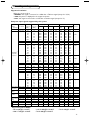
Ta b le of Signals Supported
Supported resolution
When the screen mode is
•
NORMAL, each signal is converted to a 1024 dots x 768 lines signal (except for *2,3,4).
•
TRUE, the picture is displayed in the original resolution.
•
FULL, each signal is converted to a 1364 dots x 768 lines signal (except for *3).
Computer input signals supported by this system
Ver tical Horizontal Sync Polarity Presence Screen mode RGB
Model Dots x lines frequency frequency
Horizontal Vertical Horizontal Vertical Normal True Full select
*6
Signal type
(Hz) (kHz) (4:3) (16:9)
640 x 400 70.1 31.5 NEG NEG YES YES YES
*2
YES YES --
640 x 480 59.9 31.5 NEG NEG YES YES YES YES YES STILL
72.8 37.9 NEG NEG YES YES YES YES YES --
75.0 37.5 NEG NEG YES YES YES YES YES STILL
85.0 43.3 NEG NEG YES YES YES YES YES --
100.4 51.1 NEG NEG YES YES YES YES YES --
120.4 61.3 NEG NEG YES YES YES YES YES --
848 x 480 60.0 31.0 POS POS YES YES -- YES YES WIDE2
852 x 480
*1
60.0 31.7 NEG NEG YES YES -- YES YES WIDE1
800 x 600 56.3 35.2 POS POS YES YES YES YES YES STILL
60.3 37.9 POS POS YES YES YES YES YES STILL
72.2 48.1 POS POS YES YES YES YES YES --
75.0 46.9 POS POS YES YES YES YES YES --
85.1 53.7 POS POS YES YES YES YES YES --
IBM PC/AT
*7
99.8 63.0 POS POS YES YES YES YES YES --
compatible 120.0 75.7 POS POS YES YES YES YES YES --
computers 1024 x 768 60.0 48.4 NEG NEG YES YES YES
*3
-- YES STILL
70.1 56.5 NEG NEG YES YES YES
*3
-- YES --
75.0 60.0 POS POS YES YES YES
*3
-- YES STILL
85.0 68.7 POS POS YES YES YES
*3
-- YES --
100.6 80.5 NEG NEG YES YES YES
*3
-- YES --
1152 x 864 75.0 67.5 POS POS YES YES YES -- YES STILL
1280 x768 56.2 45.1 POS POS YES YES -- -- YES WIDE1
59.8 48.0 POS NEG YES YES -- -- YES WIDE3
1360 x 765 60.0 47.7 POS POS YES YES -- -- YES
*3
WIDE1
1360 x 768 60.0 47.7 POS POS YES YES -- -- YES
*3
WIDE1
1376 x 768 59.9 48.3 NEG POS YES YES -- -- YES WIDE2
1280 x 1024 60.0 64.0 POS POS YES YES YES
*4
-- YES STILL
75.0 80.0 POS POS YES YES YES
*4
-- YES --
85.0 91.1 POS POS YES YES YES
*4
-- YES --
100.1 108.5 POS POS YES YES YES
*4
-- YES --
1600 x 1200 60.0 75.0 POS POS YES YES YES -- YES --
65.0 81.3 POS POS YES YES YES -- YES --
70.0 87.5 POS POS YES YES YES -- YES --
75.0 93.8 POS POS YES YES YES -- YES --
85.0 106.3 POS POS YES YES YES -- YES --
Work station 1280 x 1024 60.0 64.6 NEG NEG YES YES YES
*4
-- YES --
(EWS4800)
*7
71.2 75.1 NEG NEG YES YES YES
*4
-- YES --
Work station 1280 x 1024 72.0 78.1 -- -- -- -- YES
*4
-- YES
(HP)
*7
Work station 1152 x 900 66.0 61.8 C Sync C Sync -- -- YES -- YES --
(SUN)
*7
76.0 71.7 C Sync C Sync -- -- YES -- YES --
1280 x 1024 76.1 81.1 C Sync C Sync -- -- YES
*4
-- YES --
Work station 1024 x 768 60.0 49.7 -- -- -- -- YES
*3
-- YES --
(SGI) 1280 x 1024 60.0 63.9 -- -- -- -- YES
*4
-- YES --
IDC-300G
PAL625P 768 x 576 50.0 31.4 NEG NEG YES YES YES
*7
-- YES
*7
--
NTSC525P 640 x 480 59.9 31.5 NEG NEG YES YES YES
*7
MOTION NO
Supported signals for HDCP:
• 640 X [email protected]/60HZ
• 1280 X [email protected]/60HZ
• 1920 X [email protected]/60HZ
• 720 X [email protected]/60HZ
• 720 X [email protected]/60HZ
2268.1 am 03-12-2003 09:47 Pagina 19

20
*1 Only when a graphic accelator board that is capable of displaying 852 x 480.
*2 This signal is converted to a 1228 dots x 768 lines signal.
*3 The picture is displayed in the original resolution.
*4 The aspect ratio is 5:4.This signal is converted to a 960 dot x 768 line signal.
*5 Normally the RGB select mode suite for the input signals is set automatically.
If the picture is not displayed properly, set the RGB mode prepared for the input signals listed in
the table.
*6 Other screen modes (ZOOM and STADIUM) are available as well.
*7 When viewing a moving picture at a vertical frequency greater than 65Hz, the picture may
sometimes be unstable (jumpy). If this occurs, please set the refresh rate of the external
equipment to 60Hz.
To view 480i@60Hz (480 interlaced lines, 60Hz refresh rate) or 576i@50Hz (576 interlaced
lines, 50Hz refresh rate) when sync polarity is ‘Sync on Green’, set ‘RGB SELECT’ to ‘MOTION’.
What is HDCP technology?
HDCP is an acronym for High-bandwidth Digital Content Protection. High bandwidth Digital Content
Protection (HDCP) is a system for preventing illegal copying of video data sent over a Digital Visual
Interface (DVI).
If you are unable to view material via the DVI input, this does not necessarily mean the PDP is not
functioning properly.With the implementation of HDCP, there may be cases in which certain content
is protected with HDCP and might not be displayed due to the decision/intention of the HDCP
community (Digital Protection, LLC).
Note:
• While the input signals comply with the resolution listed in the table above, you may have to adjust the
position and size of the picture or the fine picture because of errors in synchronization of your computer.
• When a 1280 dot x 1024 line signal or 1600 dot x 1200 line signal is input to the monitor, the picture will
be compressed.
• This monitor has a resolution of 1365 dot x 768 line. It is recommended that the input signal should be
XGA, wide XGA, or equivalent.
• With digital input some signals are not accepted.
• The sync may be disturbed when a nonstandard signal other than the aforementioned is input.
• If you are connecting a composite sync signal, use the HD terminal.
*”IBM PC/AT” and “VGA” are registered trademarks of IBM, Inc. of the United States.
FCC Compliance notice
This equipment has been tested and found to comply with the limits for a Class B equipment,
pursuant to Part 15 of the FCC Rules. These limits are designed to provide reasonable protection
against harmful interference when the equipment is operated in a commercial environment.This
equipment generates, uses and can radiate radio frequency energy and, if not installed and used in
accordance with the instruction manual, may cause harmful interference to radio communications.
Operation of this equipment in a residential area is likely to cause harmful interference, in which case
the user will be required to correct the interference at his own expense.
2268.1 am 03-12-2003 09:47 Pagina 20
La pagina si sta caricando...
La pagina si sta caricando...
La pagina si sta caricando...
La pagina si sta caricando...
-
 1
1
-
 2
2
-
 3
3
-
 4
4
-
 5
5
-
 6
6
-
 7
7
-
 8
8
-
 9
9
-
 10
10
-
 11
11
-
 12
12
-
 13
13
-
 14
14
-
 15
15
-
 16
16
-
 17
17
-
 18
18
-
 19
19
-
 20
20
-
 21
21
-
 22
22
-
 23
23
-
 24
24


Philips F 650 GS - 2009 Manuale del proprietario
- Tipo
- Manuale del proprietario
- Questo manuale è adatto anche per
in altre lingue
Documenti correlati
Altri documenti
-
NEC PlasmaSync® 42XP10 Manuale del proprietario
-
-
Hitachi CMP5000WXE Manuale utente
-
Pioneer Flat Panel Television PDP-42MVE1 Manuale utente
-
Pioneer PLASMA DISPLAY Manuale utente
-
Yamaha PDM-4220 Manuale del proprietario
-
-
-
Hitachi P42A01 Manuale utente
-