Amprobe ACF-3000-SR Current Transducer Manuale utente
- Tipo
- Manuale utente

OPERATING INSTRUCTIONS
for
AMPROBE
®
Flexible Current Transducer
Model ACF-3000 SR
AMPROBE

2
TABLE OF CONTENTS
LIMITED WARRANTY . . . . . . . . . . . . . . . . . . . . . . . . . . . . . . . . . .3
INTRODUCTION . . . . . . . . . . . . . . . . . . . . . . . . . . . . . . . . . . . . . .4
ACF - 3000 SR ELECTRONICS PACKAGE . . . . . . . . . . . . . . . . . .4
FLEXIABLE AC CURRENT TRANSDUCER . . . . . . . . . . . . . . . . .6
OPERATION . . . . . . . . . . . . . . . . . . . . . . . . . . . . . . . . . . . . . . . . .7
MAINTENANCE . . . . . . . . . . . . . . . . . . . . . . . . . . . . . . . . . . . . . .8
BATTERY REPLACEMENT . . . . . . . . . . . . . . . . . . . . . . . . . . . . . .9
SPECIFICATIONS . . . . . . . . . . . . . . . . . . . . . . . . . . . . . . . . . . . .10

AFTER-SALE SERVICE
WARRANTY
Congratulations! Your new instrument has been quality crafted according to quality
standards and contains quality components and workmanship. It has been inspected
for proper operation of all of its functions and tested by qualified factory technicians
according to the long-established standards of our company.
Your instrument has a limited warranty against defective materials and/or workmanship
for one year from the date of purchase provided that, in the opinion of the factory, the
instrument has not been tampered with or taken apart.
Should your instrument fail due to defective materials, and/or workmanship
during this one-year period, a no charge repair or replacement will be made to
the original purchaser. Please have your dated bill of sale, which must identify
the instrument model number and serial number and call the number listed
below:
Repair Department
ATP– Amprobe, TIF, Promax
Miramar, FL
Phone: 954-499-5400
800-327-5060
Fax: 954-499-5454
Website: www.amprobe.com
Please obtain an RMA number before returning product for repair.
Outside the U.S.A. the local representative will assist you. Above limited warranty
covers repair and replacement of instrument only and no other obligation is stated or
implied.
3

4
! ! WARNING !!
(Do not use until you have read this!)
High-voltage potentials may exist in the vicinity of the desired current measurements.
Use locally approved safety procedures when working near high-voltage potentials. It
is recommended not to install the Flexible Transducer around a live bus that is at a
high-voltage potential. If installation is not possible when the bus is disconnected from
main supply, use appropriate gloves and/or equipment that are approved for working
around high-voltage potentials when installing the Flexible Transducer in the vicinity of
these hazardous potentials.
INTRODUCTION
The AMPROBE Flexible AC Current Transducer Model ACF-3000 SR is an assembly
similar in purpose to a CT or current transformer. It may be used to measure AC
currents from a low as a few amps to a maximum of 3.0kA rms. The device output is
an analog voltage that is proportional to the current in the conductor. The output signal
is isolated from the hazardous conductor potential and is an exact replica of the AC
current wave form in the conductor. The output signal is available via a 2 pin snap
connector.
ACF-3000 SR ELECTRONICS PACKAGE
The ACF-3000SR electronics package is permanently connected to the transducer.
When the ACF-3000 SR is turned on, the LED mounted behind the front label blinks
once, then goes out to minimize drain on the battery. When the batteries are nearing
the end of their life the LED flashes approximately twice per second, the batteries
should be replaced and as soon as possible. If the LED fails to flash once when the
unit is turned on, the batteries are dead, replace immediately.
The ACF-3000 SR comes equipped with an external mini jack located on the package.
This is for those wanting to supply power to the ACF-3000 SR for a longer period than
the internal battery life will allow. An external DC power supply is available for this
purpose but is sold as an option. The power required is +3.0VDC/10mA.

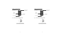
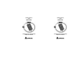
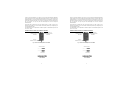
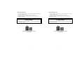
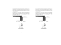
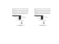
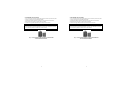
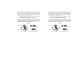
FLEXIBLE AC CURRENT
TRANSDUCER
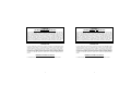
Fig. 1 - ACF 3000 SR ELECTRONICS PACKAGE
Fig. 2b - ACF-5CE: OUTPUT SIGNAL
ADAPTER SUPPLIED FOR THE DM-III
5
2 PIN SNAP FEMALE
OUTPUT CONNECTOR
EXTERNAL POWER
CONNECTOR
BATTERY
LOW
INDICATOR
TO TRANSDUCER
OUTPUT
TO CT
GREEN / RED
INDICATOR
FLEXIBLE AC CURRENT
TRANSDUCER
Fig. 1 - ACF 3000 SR ELECTRONICS PACKAGE
Fig. 2b - ACF-5CE: OUTPUT SIGNAL
ADAPTER SUPPLIED FOR THE DM-III
5
2 PIN SNAP FEMALE
OUTPUT CONNECTOR
EXTERNAL POWER
CONNECTOR
BATTERY
LOW
INDICATOR
TO TRANSDUCER
OUTPUT
TO CT
GREEN / RED
INDICATOR

6
The ACF-3000 SR design utilizes the light weight and flexibility of the Flexible AC
Current Transducer. This transducer is a versatile current probe that may be wrapped
around most conductors. Its application versatility and high voltage isolation rating
clearly distinguish the ACF-3000 SR from other current measuring methods. The
measuring transducer is constructed from nonferrous materials, minimizing any circuit
loading.
Note: The ACF-3000 SR will produce twice the output if you wrap the
transducer round the conductor twice.
The frequency response of the ACF-3000 SR is wide compared to conventional CTs.
This allows the user to monitor a much wider range of line harmonic components than
conventional CTs allow. The ACF-3000 SR was designed to be very flexible, larger in
aperture and smaller in cross section than many conventional CTs. This allows
measurement in tight places as never before possible.
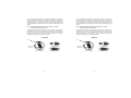
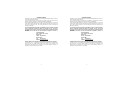
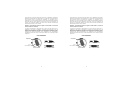
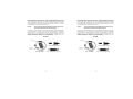
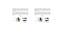
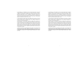
OPERATION
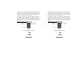
LATCH
ELECTRONICS
PACKAGE
Fig. 3 - ACF-3000 SR
Fig. 5 - LATCH CLOSED
Fig. 4 - LATCH OPEN
6
The ACF-3000 SR design utilizes the light weight and flexibility of the Flexible AC
Current Transducer. This transducer is a versatile current probe that may be wrapped
around most conductors. Its application versatility and high voltage isolation rating
clearly distinguish the ACF-3000 SR from other current measuring methods. The
measuring transducer is constructed from nonferrous materials, minimizing any circuit
loading.
Note: The ACF-3000 SR will produce twice the output if you wrap the
transducer round the conductor twice.
The frequency response of the ACF-3000 SR is wide compared to conventional CTs.
This allows the user to monitor a much wider range of line harmonic components than
conventional CTs allow. The ACF-3000 SR was designed to be very flexible, larger in
aperture and smaller in cross section than many conventional CTs. This allows
measurement in tight places as never before possible.
OPERATION
LATCH
ELECTRONICS
PACKAGE
Fig. 3 - ACF-3000 SR
Fig. 5 - LATCH CLOSED
Fig. 4 - LATCH OPEN

7
The ACF-3000 SR was designed to allow the operator to connect this measurement
device around a conductor without disconnecting the conductor as many CTs presently
demand. The Flexible AC Current Transducer is installed around the conductor with the
moulded-in-arrow on the latch (Fig.4) pointing in the direction of conventional current
flow. Conventional current flow is defined as current flowing from the positive to the
negative potential, or in case of AC current the arrow should face the load.
The Flexible AC Current Transducer must be installed with the interconnection cable
on the outside of the loop when the latch is engaged. The polarity arrow, the double
insulation, and the warning symbols will all be on the outside of the loop.
There is minimal shock hazard using the ACF-3000 SR, as the transducer does not
generate high voltages at low frequencies. Each transducer has been Hi-Pot tested to
several thousand volts with no voltage breakdown. This particular characteristic allows
high-current measurement (with a wide frequency bandwidth) of conductors at less
than 600VAC potential to earth. Do not exceed the minimum bending radius of the
Flexible AC Current Transducer when installing the transducer around the conductor.
Exceeding the bending radius will degrade the measurement accuracy.
Make sure the Flexible AC Current Transducer and its output cable are clean before
installing them around the conductor. If the transducer and cable are not clean the
contaminants on them may provide a conductive path for a high-voltage breakdown.
Also, check the transducer and output cable for cuts and abrasions. Do not use the
transducer if damaged.
To measure AC current, open the ACF-3000 SR by squeezing the latch, encircle the
conductor to be measured, then snap the ACF-3000 SR ends together (Fig.4). Connect
the ACF-3000 SR output cable to your measuring instrument using an adaptor.

8
Maintenance
Preventative maintenance primarily consists of cleaning the transducers and cables to
prevent surface contamination. Use a mild detergent and water to clean the
transducers and cables. Remove the detergent with clear water, then wipe dry with a
clean cloth.
Note: The use of solvents as cleaners is not recommended unless thoroughly
tested and found harmless to all surfaces and parts. Do not submerse
current transducer into water or other fluids.

9
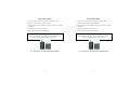
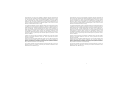
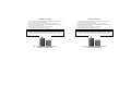
BATTERY REPLACEMENT
1) Using a coin, turn the lock from the closed position to the open position.
2) Open the cover of the battery compartment by lifting it.
3) Replace batteries (note the polarization marked on the bottom of the battery
compartment).
4) Replace the cover of the battery compartment.
5) Turn the lock from the open to the closed position.
! ! SAFETY WARNING ! !
Before removing the battery cover, make sure that the Flexible AC Current
Transducer is removed from around any active conductor.
FIG. 6 - BACK OF ACF - 3000 SR W/ BATTERY COVER REMOVED
9
BATTERY REPLACEMENT
1) Using a coin, turn the lock from the closed position to the open position.
2) Open the cover of the battery compartment by lifting it.
3) Replace batteries (note the polarization marked on the bottom of the battery
compartment).
4) Replace the cover of the battery compartment.
5) Turn the lock from the open to the closed position.
! ! SAFETY WARNING ! !
Before removing the battery cover, make sure that the Flexible AC Current
Transducer is removed from around any active conductor.
FIG. 6 - BACK OF ACF - 3000 SR W/ BATTERY COVER REMOVED

10
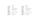
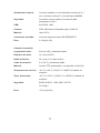
SPECIFICATIONS
Measuring Range: 15A - 3000A
Output Sensitivity: 1mV/3A
Accuracy: (at 250C) ±1% of range
Frequency Range: 10Hz to 5kHz
Phase Error: ±1º (45 to 65 Hz) ±10º (at 5kHz)
Linearity: ±0.2% of reading from 10% to 100% of range
Position Sensitivity: ±2% of range, cable >25mm (1”) from coupling
External Field: ±1% with cable >200m (8”) from head
Minimum Load: 100kΩ for specified accuracy
Noise Level 1.0mV rms (0.3% of range)
Operating Temperature: -20
o
C to 85
o
C (-4
o
F to 185
o
F) Electronics
Storage Temperature: -20
o
C to 85
o
C (-4
o
F to 185
o
F) Electronics
Gain Variation ±0.08%/
o
C
Common Mode Voltage: Voltage between the Output and Earth must not exceed
30V.
Power Supply: 2 x AA/MN1500/LR6 (1.5V) batteries.
Battery Life: 4000 hours, 3000 hours typical (4 months cont.)
Low Battery Indication: Red LED flashing
External Power: Battery eliminator, via 2.1mm connector, 3V DC Socket
type A16M500
Safety: Voltage between the Output and Earth must not exceed
30V.
EMC: EN61326: 1998
Enclosure: IP5X, Flame retardant UL94-VO rated
Material: Valox 357 X
Output Connections: Hypotronics connector type DO1EEB306FST
Weight: 0.19kg (0.4lb)
Measuring Head
Cable length: 610mm (24 inches), double insulated
Cable Diameter: 14.3mm (0.562 inches)
Bend Radius: 38.1mm (1.5 inches) minimum
Connecting Cable: 2m (78.7 inches) long, double insulated
Material: TPE rubber Polypropylene, UL94-VO rated
Operating Temperature: -20
o
C to +90
o
C (-4
o
F to 194
o
F) Head
Storage Temperature: -40
o
C to _105
o
C (-40
o
F to 221
o
F) Head
Safety: BS EN 61010-1: 1993, 600V CAT III Pol. Deg 2
Weight: 0.18kg (0.4 lb)
10
SPECIFICATIONS
Measuring Range: 15A - 3000A
Output Sensitivity: 1mV/3A
Accuracy: (at 250C) ±1% of range
Frequency Range: 10Hz to 5kHz
Phase Error: ±1º (45 to 65 Hz) ±10º (at 5kHz)
Linearity: ±0.2% of reading from 10% to 100% of range
Position Sensitivity: ±2% of range, cable >25mm (1”) from coupling
External Field: ±1% with cable >200m (8”) from head
Minimum Load: 100kΩ for specified accuracy
Noise Level 1.0mV rms (0.3% of range)
Operating Temperature: -20
o
C to 85
o
C (-4
o
F to 185
o
F) Electronics
Storage Temperature: -20
o
C to 85
o
C (-4
o
F to 185
o
F) Electronics
Gain Variation ±0.08%/
o
C
Common Mode Voltage: Voltage between the Output and Earth must not exceed
30V.
Power Supply: 2 x AA/MN1500/LR6 (1.5V) batteries.
Battery Life: 4000 hours, 3000 hours typical (4 months cont.)
Low Battery Indication: Red LED flashing
External Power: Battery eliminator, via 2.1mm connector, 3V DC Socket
type A16M500
Safety: Voltage between the Output and Earth must not exceed
30V.
EMC: EN61326: 1998
Enclosure: IP5X, Flame retardant UL94-VO rated
Material: Valox 357 X
Output Connections: Hypotronics connector type DO1EEB306FST
Weight: 0.19kg (0.4lb)
Measuring Head
Cable length: 610mm (24 inches), double insulated
Cable Diameter: 14.3mm (0.562 inches)
Bend Radius: 38.1mm (1.5 inches) minimum
Connecting Cable: 2m (78.7 inches) long, double insulated
Material: TPE rubber Polypropylene, UL94-VO rated
Operating Temperature: -20
o
C to +90
o
C (-4
o
F to 194
o
F) Head
Storage Temperature: -40
o
C to _105
o
C (-40
o
F to 221
o
F) Head
Safety: BS EN 61010-1: 1993, 600V CAT III Pol. Deg 2
Weight: 0.18kg (0.4 lb)


MODED‘EMPLOI
pour
AMPROBE®
Transducteurdecourantflexible
ModèleACF-3000SR
MODED‘EMPLOI
pour
AMPROBE®
Transducteurdecourantflexible
ModèleACF-3000SR

2
TABLEDESMATIERES
GARANTIE........................................................................................................3
INTRODUCTION...............................................................................................4
BLOCELECTRONIQUEDEL’ACF-3000SR ....................................................4
TRANSDUCTEURBOUCLEFLEXIBLEDECOURANTAC.............................6
FONCTIONNEMENT.........................................................................................7
MAINTENANCE ................................................................................................8
REMPLACEMENTDESPILES..........................................................................9
SPECIFICATIONS..........................................................................................10
2
TABLEDESMATIERES
GARANTIE........................................................................................................3
INTRODUCTION...............................................................................................4
BLOCELECTRONIQUEDEL’ACF-3000SR....................................................4
TRANSDUCTEURBOUCLEFLEXIBLEDECOURANTAC.............................6
FONCTIONNEMENT.........................................................................................7
MAINTENANCE................................................................................................8
REMPLACEMENTDESPILES..........................................................................9
SPECIFICATIONS..........................................................................................10

3
GARANTIELIMITEE
Félicitations!Vousvoilàpropriétaired'uninstrumentAMPROBE
®
fabriquésuivantles
normesdequalitélesplusélevées.
Lebonfonctionnementdecetinstrumentaétévérifiéenusinepardestechniciens
qualifiéssuivantdesprocéduresstrictesbienétabliesdeAMPROBE
®
.
VotreinstrumentAMPROBE
®
estcouvertparunegarantielimitéedeunanàpartirde
ladated'achatcontretoutdéfautdematièreset/oudefabricationpourautantquele
sceaun'aitpasétébrisénique,del'avisdestechniciensdel'usine,l'instrumentn'ait
étéaltéréoudémonté
Si votre instrument devait connaître une défaillance suite à un défaut de matière
et/ou de fabrication pendant la période de garantie d'un an, renvoyez-le
accompagné d'une copie de votre facture d'achat datée et spécifiant le numéro
de modèle et le numéro de série de l'instrument et appelez au numéro ci-
dessous :
RepairDepartment
ATP–Amprobe,TIF,Promax
Miramar,FL
Phone: 954-499-5400
800-327-5060
Fax: 954-499-5454
Website:www.amprobe.com
VeuillezobtenirunnuméroRMAavantderetournerleproduitpourréparation
EndehorsdesU.S.A.,lereprésentantAmprobedevotrerégionestàvotredisposition
pourvousaider.Lagarantielimitéeci-dessusnecouvrequelaréparationetle
remplacementdel'instrumentetn'impliqueaucuneautreobligationexpresseou
implicitedelapartdufabricantouduvendeur.

4
!!AVERTISSEMENT!!
(N'utilisezpasl'appareilavantd'avoirluceci!)
Despotentielsdangereuxpeuventêtreprésentsdanslevoisinagedesendroits
deprisedemesuredecourantchoisis.Suivezlesconsignesdesécuritéen
vigueurlorsquevoustravaillezàproximitédepotentielsdangereux.Ilest
déconseilléd'installerletransducteurflexibleauxenvironsd'unreseausous
tensionquisoitàunpotentieldangereux.Sil'installationn'estpaspossible
lorsquelebusestdésactivéouaveclecourantcoupé,porteztoujoursdes
gantsadéquatset/ouunéquipementdeprotectionapprouvépourletravailà
proximitédepotentielsdangereuxsivousinstallezletransducteurflexible
danslevoisinagedecespotentielsdangereux.
INTRODUCTION
LetransducteurflexibledecourantalternatifAMPROBE,modèleACF-3000SR,est
uninstrumentsimilaireàuntransformateurdecourant(TC).Onpeutl'utiliserpour
mesurerdesintensitésdecourantsalternatifspouvantallerdequelquesampères
jusqu'àunmaximumde3,0kAeffectifs.Ensortie,l'appareilprésenteunetension
analogiqueproportionnelleàl'intensitéducourantcirculantdansleconducteur
mesuré.Lesignaldesortieestisolédupotentieldangereuxduconducteuret
constituel'exacterépliquedelaformed'ondeducourantalternatifpassantdansle
conducteur.
Lesignaldesortiesetransmetviaunconnecteurrapideà2broches.
BLOCELECTRONIQUEDEL'ACF-3000SR
Leblocélectroniquedel'ACF-3000SRestraccordéenpermanenceautransducteur.

5
Lorsqu'onmetl'ACF-3000SRsoustension,levoyantLEDsituéderrièrel'étiquetteà
l'avantclignoteunefoispuiss'éteintafind'économiserlespiles.Lorsquelespilessont
presqueépuisées,cevoyantclignoteenvirondeuxfoisparsecondeetilnefautalors
pastarderàremplacerlespiles.Silevoyantneclignotepaslorsquel'instrumentest
missoustension,c'estquelespilessontdechargéesetilfautlesremplacer
immédiatement.
L'ACF-3000SRestéquipéd'unminijackexternesituésurlebloc.Celui-cisertà
alimenterl'ACF-3000SRsionveututiliserl'instrumentpendantpluslongtempsque
nelepermettentlespiles.
UnealimentationDCestdisponibleàceteffetenoption.L'alimentationrequiseestde
+3,0VDC/10mA.
TRANSDUCTEURFLEXIBLEDECOURANTALTERNATIF
Fig1–BLOCELECTRONIQUEDEL’ACF-3000SR
RACCORDRAPIDE
FEMELLEADEU
X
BROC
HES
CONNECTEUR
D’ALIMENTATION
EXTERNE
VERSLE
TRANSDUCTEUR
Fig2b:ACF-5CE:SIGNAL
ENSORTIEADAPTATEUR
FOURNIPOURLEDM-II
PRO&DMIIICE
A
CAPTEUR
SORTIEADM-III
5
Lorsqu'onmetl'ACF-3000SRsoustension,levoyantLEDsituéderrièrel'étiquetteà
l'avantclignoteunefoispuiss'éteintafind'économiserlespiles.Lorsquelespilessont
presqueépuisées,cevoyantclignoteenvirondeuxfoisparsecondeetilnefautalors
pastarderàremplacerlespiles.Silevoyantneclignotepaslorsquel'instrumentest
missoustension,c'estquelespilessontdechargéesetilfautlesremplacer
immédiatement.
L'ACF-3000SRestéquipéd'unminijackexternesituésurlebloc.Celui-cisertà
alimenterl'ACF-3000SRsionveututiliserl'instrumentpendantpluslongtempsque
nelepermettentlespiles.
UnealimentationDCestdisponibleàceteffetenoption.L'alimentationrequiseestde
+3,0VDC/10mA.
TRANSDUCTEURFLEXIBLEDECOURANTALTERNATIF
Fig1–BLOCELECTRONIQUEDEL’ACF-3000SR
RACCORDRAPIDE
FEMELLEADEU
X
BROCHES
CONNECTEUR
D’ALIMENTATION
EXTERNE
VERSLE
TRANSDUCTEUR
Fig2b:ACF-5CE:SIGNAL
ENSORTIEADAPTATEUR
FOURNIPOURLEDM-II
PRO&DMIIICE
A
CAPTEUR
SORTIEADM-III

6
L'ACF-3000SRtirepartidudesignpoidsplumeetdelaflexibilitédutransducteur
flexibledecourantalternatif.Cetransducteurestuncapteurdecourantpolyvalentqui
peuts'enroulerautourdelaplupartdesconducteurs.Lapolyvalencedeses
applicationsetsaclassed'isolationcontreleshautestensionsdistinguentnettement
L'ACF-3000SRdesautressystèmesdemesuredecourant.Letransducteurde
mesuresestconstituédematériauxnonferreuxafindeminimisertoutedécharge
éventuelleprovenantducircuitàcontrôler.
Remarque:l'ACF-3000SRdonneraunsignaldesortiedoublesionl'enroule
deuxfoisautourduconducteur.
Laréponseenfréquencedel'ACF-3000SRestassezlargeparrapportauxTC
traditionnels.Celapermetàl'utilisateurdecontrôlerunéventailpluslargede
composantesharmoniquesdelignequenelepermettentlesTCtraditionnels.L'ACF-
3000SResttrèsflexibleparconception,avecuneouverturepluslargeetunprofil
transversalpluspetitquebeaucoupdeTCtraditionnels.Cescaractéristiques
permettentdeprendredesmesuresàdesendroitsdifficilesoùcen'étaitpaspossible
auparavant.
FONCTIONNEMENT
Fig.4–LOQUETEAUOUVERT
Fig.5–LOQUETEAUFERME
LOQUETEAU
BLOC
ELECTRONIQUE
Fig3:ACF-3000SR

7
L'ACF-3000SRaétéconçupourpermettreàl'opérateurdeplacerl'instrumentde
mesureautourd'unconducteursansdevoirdéconnecterleconducteurcommec'estle
casavecbeaucoupdeTCactuels.LetransducteurflexibledecourantCAs'installe
autourduconducteuraveclaflèchemouléesurleloqueteau(Fig.4)pointantdansla
directiondufluxdecourantconventionnel.Lefluxdecourantconventionnelestle
courants'écoulantdupotentielpositifaupotentielnégatif,oudanslecasdecourant
alternatif,laflèchedoitfairefaceàlacharge.
LetransducteurflexibledecourantACdoitêtreinstalléaveclecâbled'interconnexion
àl'extérieurdelabouclelorsqueleloqueteauestengagé.Laflèchedepolarité,la
doubleisolationetlessymbolesd'avertissementseronttousàl'extérieurdelaboucle.
Avecl'ACF-3000SR,lerisqued'électrocutionestminimecarletransducteurne
génèreaucunehautetensionàbassesfréquences.Chaquetransducteuraététesté
"hautpotentiel"àplusieursmilliersdevoltssansinterruptiondetension.Cette
caractéristiqueparticulièrepermetdemesurerdehautesintensitésdecourantdes
conducteurs(avecunegrandelargeurdebandedefréquence)àpotentielàlaterre
demoinsde600AC.
Lorsquevousleplacezautourduconducteur,nedépassezpaslerayondecourbure
minimaldutransducteurflexibledecourantAC,sinonlaprécisiondesmesures
pourraits'enressentir.
Assurez-vousqueletransducteurflexibledecourantCAetsoncâbledesortiesoient
propresavantdelesplacerautourduconducteur.S'ilsnesontpaspropres,les
salissurespeuventdevenirconductricesdehautestensionsaccidentelles.Demême,
vérifiezsiletransducteuretlecâbledesortien'ontpasdecoupuresnid'abrasions.
Nepasutiliserletransducteurs'ilestendommagé.
Pourmesurerl'intensitédecourantalternatif,ouvrezl'ACF-3000SRenpinçantle
loqueteau,entourezleconducteuràmesurerpuisenclenchezensemblelesdeux
extrémitésdel'ACF-3000SR(Fig.4).

8
Raccordezlecâbledesortiedel'ACF-3000SRàvotreappareildemesureaumoyen
d'unadaptateur.
Sélectionnezlaplagedemesuredel'ACF-3000SRde300oude3000Aselonle
réglagedel'instrumentdemesure.
MAINTENANCE
Lamaintenancepréventiveconsisteprincipalementànettoyerlestransducteursetles
câblespourempêcherunecontaminationensurface.Utilisezundétergentdouxetde
l'eaupourlesnettoyer.Eliminezledétergentavecdel'eauclaire,puisséchezavecun
chiffonpropre.
REMARQUE:Ilestdéconseilléd'utiliserdessolvantscommeproduitde
nettoyageàmoinsqu'ilsn'aientétéconvenablementtestéssurtoutesles
surfacesetlespiècesetquel'onaitconstatéqu'ilsétaientsûrs.Nepas
immergerletransducteurdansl'eaunidansd'autresliquides.

9
REMPLACEMENTDESPILES
1)Al'aided'unepiècedemonnaie,tournezleboutondefermeturedelaposition
ferméeàlapositionouverte.
2)Ouvrezlecouvercleducompartimentdespilesenlesoulevant.
3)Remplacezlespiles(notezlapolaritémarquéeaufondducompartiment).
4)Replacezlecouvercle.
5)Tournezleboutondefermeturedelapositionouverteàlapositionfermée.
!!AVERTISSEMENT!!
Pourdesraisonsdesécurité,avantd'enleverlecouvercleducompartimentdespiles,
assurezvousqueletransducteurflexibledecourantCAnesoitpasinstalléautour
d'unconducteursoustension.
Fig6:ARRIEREDEL’ACF-3000SRAVECCOUVERCLE
DESPILESENLEVE
La pagina si sta caricando...
La pagina si sta caricando...
La pagina si sta caricando...
La pagina si sta caricando...
La pagina si sta caricando...
La pagina si sta caricando...
La pagina si sta caricando...
La pagina si sta caricando...
La pagina si sta caricando...
La pagina si sta caricando...
La pagina si sta caricando...
La pagina si sta caricando...
La pagina si sta caricando...
La pagina si sta caricando...
La pagina si sta caricando...
La pagina si sta caricando...
La pagina si sta caricando...
La pagina si sta caricando...
La pagina si sta caricando...
La pagina si sta caricando...
La pagina si sta caricando...
La pagina si sta caricando...
La pagina si sta caricando...
La pagina si sta caricando...
La pagina si sta caricando...
La pagina si sta caricando...
La pagina si sta caricando...
La pagina si sta caricando...
La pagina si sta caricando...
La pagina si sta caricando...
La pagina si sta caricando...
La pagina si sta caricando...
La pagina si sta caricando...
La pagina si sta caricando...
La pagina si sta caricando...
La pagina si sta caricando...
La pagina si sta caricando...
La pagina si sta caricando...
La pagina si sta caricando...
-
 1
1
-
 2
2
-
 3
3
-
 4
4
-
 5
5
-
 6
6
-
 7
7
-
 8
8
-
 9
9
-
 10
10
-
 11
11
-
 12
12
-
 13
13
-
 14
14
-
 15
15
-
 16
16
-
 17
17
-
 18
18
-
 19
19
-
 20
20
-
 21
21
-
 22
22
-
 23
23
-
 24
24
-
 25
25
-
 26
26
-
 27
27
-
 28
28
-
 29
29
-
 30
30
-
 31
31
-
 32
32
-
 33
33
-
 34
34
-
 35
35
-
 36
36
-
 37
37
-
 38
38
-
 39
39
-
 40
40
-
 41
41
-
 42
42
-
 43
43
-
 44
44
-
 45
45
-
 46
46
-
 47
47
-
 48
48
-
 49
49
-
 50
50
-
 51
51
-
 52
52
-
 53
53
-
 54
54
-
 55
55
-
 56
56
-
 57
57
-
 58
58
-
 59
59


Amprobe ACF-3000-SR Current Transducer Manuale utente
- Tipo
- Manuale utente
in altre lingue
Documenti correlati
Altri documenti
-
Snap-On TECHANGLE Manuale utente
-
Philips HR 8909 Manuale utente
-
Wolf ICBMW30-230 Manuale utente
-
Peerless MOD-ACF-W Manuale utente
-
Aeg-Electrolux MCC4060EA Manuale utente
-
Porsche 9Y0.915.686.C Guida d'installazione
-
 Screening Eagle Pundit Live Array Guida Rapida
-
Monster Oron Gaming Chair Istruzioni per l'uso
