

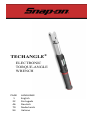
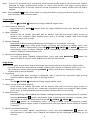
1
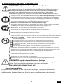
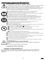
IMPORTANT SAFETY INSTRUCTIONS
WARNING Risk of flying particles.
Over-torquing can cause breakage. Force against flex stops on flex head can cause head
breakage. An out of calibration angle wrench can cause part or tool breakage. Broken
hand tools, sockets or accessories can cause injury. Excess force can cause crowfoot or
flare nut wrench slippage.
Read this manual completely before using ELECTRONIC WRENCH.
To insure accuracy, work must not move in angle mode.
For personal safety and to avoid wrench damage, follow good professional tool and
fastener installation practices.
Periodic recalibration is necessary to maintain accuracy.
Wear safety goggles, user and bystanders.
Be sure all components, including all adaptors, extensions, drivers and sockets are
rated to match or exceed torque being applied.
Observe all equipment, system and manufacturer's warnings, cautions and
procedures when using this wrench.
Use correct size socket for fastener.
Do not use sockets showing wear or cracks.
Replace fasteners with rounded corners.
To avoid damaging wrench: Never use wrench with power off. Always turn ON
wrench so applied torque is being measured.
Do not press POWER q while torque is applied or while wrench is in motion.
Never use this wrench to break fasteners loose.
Do not use extensions, such as a pipe, on handle of wrench.
Check that wrench capacity matches or exceeds each application before
proceeding.
Verify calibration if dropped.
Make sure ratchet direction lever is fully engaged in correct position.
Verify calibration of wrench if you know or suspect its capacity has been exceeded.
Do not force head of flex head drives against stops.
Always pull - do not push - on wrench handle and adjust your stance to prevent a
possible fall should something give.
Do not attempt to recharge Alkaline cells.
Store wrench in dry place.
Remove batteries when storing wrench used for periods longer than 3 months.
WARNING Electrical Shock Hazard.
Electrical shock can cause injury. Plastic handle is not insulated.
Do not use on live electrical circuits.
SAVE THESE INSTRUCTIONS
Disclaimer
Operation of TechAngle
®
Wrench is not warranted in a EU member state if operating
instructions are not in that State’s language. Contact Snap-on if a translation is needed.

2
Specifications
Head Type
Square drive 72 or 80 teeth, sealed flex
Display
DISPLAY TYPE: Dot Matrix LCD (192 x 65 Resolution)
VIEWING DIRECTION: 6:00
BACKLIGHT: WHITE (LED)
Sealed Button Pad
POWER - ON/OFF and torque and angle re-zero
ENTER - measurement mode select and menu entry
UP – increments torque and angle settings and menu navigation
DOWN - decrements torque and angle settings and menu navigation
UNITS - units select (ft-lbs, in-lbs, Nm, Kgm, Kg-cm, dNm) and enter PSET (preset) menu
LCD BACKLIGHT – Illuminates all screens and last peak torque or angle recall
Functions
Set - torque or angle target
Track - real time display of torque or accumulated angular rotation with progress lights
Peak Hold – 10 sec. flashing of peak torque or alternating peak torque/angle on release of
torque
Peak Recall - display last peak torque or peak torque/angle on button press
Memory - display of last 50 peak torque or peak torque/angle readings
Accuracy
Temperature: @ 22°C (72°F)
Angle: ±1% of reading ±1° @ angular velocity > 10°/sec < 180°/sec ± 1° of test fixture
CW CCW
±2% ±3% of reading, 20% to 100% of full scale
Torque: ±4% ±6% of reading, 10% to 19% of full scale
(unflexed) ±8% ±10% of reading, 5% to 9% of full scale
Dimensions: Length / Weight
Preset Range
ANGLE: 0 to 360° CW or CCW (Display Resolution 1°)
TORQUE: (Display Range and Resolution as shown below)
Operating Temperature: 0°F to 130°F (-18°C to 54°C)
Storage Temperature: 0°F to 130°F (-18°C to 54°C)
Measurement Drift: ANGLE: -0.12 Angular Degrees per Degree C
TORQUE: +0.01% of reading per Degree C
Humidity: Up to 90% non-condensing
Battery: Three "AA" Alkaline Cells, up to 80 hours continuous operation
Default Auto Shut-off: After 2 minutes idle – (Adjustable, see Advanced Settings)
Model Length Weight
ATECH1FR240B 16.4 in. 1.9 lbs.
ATECH2FR100B 17.9 in. 2.3 lbs.
ATECH3FR250B 26.6 in. 3.7 lbs.
Model Square Drive ft-lb in-lbs Nm Kgm kg-cm dNm overload (ft-lb)
ATECH1FR240B ¼ in. 1.00-20.00 12.0-240.0 1.36-27.12 N/A 13.8-276.5 13.6-271.2 25
ATECH2FR100B ⅜ in. 5.0-100.0 60-1200 6.8-135.6 N/A 69-1383 68-1356 125
ATECH3FR250B ½ in. 12.5-250.0 150-3000 16.9-339.0 1.73-34.56 N/A N/A 312

3
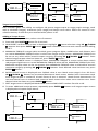
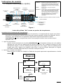
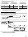
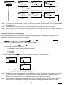
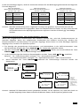
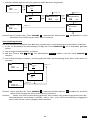
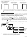
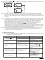
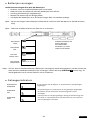
User Instructions
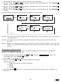
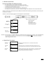
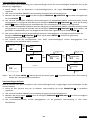
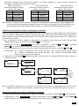
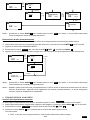
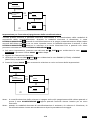
Basic Functions (Quick Start)
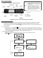
Figure 1
Install three fresh "AA" cells into wrench handle.
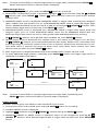
Wrench Power On Sequence
Note: Do not turn on wrench while torque is applied, otherwise torque zero offset will be incorrect
and wrench will indicate a torque reading when torque is released. If this occurs, re-zero
wrench by momentarily pressing POWER q button while wrench is on a stable surface with no
torque applied.
1. Turn On Wrench.
Momentarily press POWER q button. Snap-on logo is displayed followed by torque re-
zeroing screen. If previous measurement was angle measurement, then angle re-zeroing
screen follows the torque zeroing screen. After re-zeroing, the target torque or target angle
screen is displayed depending on previous measurement mode.
2. Select Measurement Mode.
Toggle between target TORQUE and ANGLE screens by repeatedly pressing
ENTER button.
MODE
COUNT
AUDIBLE ALERT
PROGRESS LIGHTS
Yellow - First light indicates 40% of target torque
or angle reached, Second indicates 60%
of target reached, Third indicates 80% of
target reached.
Green - Indicates target torque or angle reached.
Red - Indicates exceeded torque or angle
target+4% for targets above 20% to
100% of F.S. or target+10% for targets
from 5% to 20% of F.S, or exceeded
MAXIMUM Preset target (Note: Yellow
lights also turn on with red).
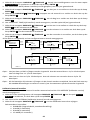
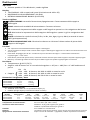
MODE SELECT, MENU ENTRY AND ENTER BUTTON
INCREMENT
BUTTON
ON/OFF
AND
RE-ZERO
BUTTON
DECREMENT
BUTTON
LCD BACKLIGHT
AND
PEAK TORQUE/ANGLE
RECALL BUTTON
UNITS AND
PRESET ENTRY
BUTTON
TORQUE AND/OR
ANGLE DISPLAY
BATTERY
CONDITION
PROGRESS
LIGHTS
PROGRESS
LIGHTS
DATA
STORAGE
ALERT
00
250.0 FT-LB
TORQUE ZEROING
ANGLE ZEROING
--
SET STILL
00
180 DEG
Target Angle Screen
ENTER
button
Target Torque Screen
ENTER
button
00
ANGLE ZERO REQ
180 DEG
POWER
button

4
Note: If wrench is powered up in torque only measurement mode, angle is not zeroed until mode is
changed to angle measurement mode, at which time torque and angle zeroing begins
automatically after 2 seconds. Wrench should be placed on a stable surface with no torque
applied.
Note: Pressing ENTER button while angle is zeroing will abort zeroing function to allow user to
select another measurement mode.
Torque Mode
1. Set Target.
Use UP /DOWN buttons to change TORQUE target value.
2. Select Units of Measure.
Repeatedly press UNITS U button while on target TORQUE screen until desired units are
displayed.
3. Apply TORQUE.
Grasp center of handle, (DO NOT pull on battery end-cap) and slowly apply torque to
fastener until progress lights display green and a ½ second audible alert and handle
vibration alerts user to stop.
4. Release TORQUE.
Note peak TORQUE reading flashing on LCD display for 10 seconds. Pressing
BACKLIGHT button while peak torque is flashing will continue to display value until
button is released. Momentarily press UP /DOWN , ENTER or UNITS U button to
immediately return to target TORQUE screen. Reapplying TORQUE will immediately start
another TORQUE measurement cycle.
5. Recall Peak TORQUE Reading
To recall last peak TORQUE measurement, press and hold BACKLIGHT button for
approximately 3 seconds. Peak TORQUE will flash for 10 seconds.
Angle Mode
Note: Do not apply torque while torque and angle are zeroing otherwise torque zero offset will be
incorrect and wrench will indicate an angle reading when torque is released. If this occurs, re-
zero wrench by momentarily pressing POWER q button with wrench setting on a stable
surface with no torque applied.
1. Angle Zero
If "ANGLE ZERO REQ" message is displayed, wait 2 seconds for automatic angle zeroing
sequence before applying torque or moving wrench.
2. Set target.
Use UP /DOWN buttons to change target ANGLE value.
3. Apply Torque and Rotate Wrench.
Grasp center of handle, (DO NOT pull on battery end-cap) and slowly apply torque to
fastener and rotate wrench at a moderate consistent speed until progress lights display
green and a ½ second audible alert and handle vibration alerts user to stop.
4. Release torque.
Note alternating peak TORQUE and ANGLE readings flashing on LCD display for 10 seconds.
Pressing BACKLIGHT button while peak angle is flashing will continue to display value
until button is released. Momentarily press UP /DOWN , ENTER or
UNITS U button to immediately return to target ANGLE screen. Reapplying torque
(ratcheting) before target screen is displayed will continue ANGLE accumulation as wrench
is rotated.
5. Recall Peak ANGLE Reading
To recall last peak ANGLE measurement, press and hold BACKLIGHT button for
approximately 3 seconds. Peak TORQUE and ANGLE will be displayed alternately for 10
seconds.

5
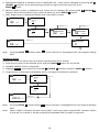
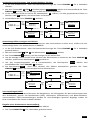
Mode Cycle Count
TechAngle
®
mode cycle count feature is used to indicate number of
times wrench has reached target torque in torque measurement
mode or target angle in angle measurement mode.
Torque and Angle Mode Cycle Counting
1. Numerical counter located in top right of target torque or target angle screen will increment
after each torque or angle cycle if applied torque or angle has reached target value.
2. When toggling between torque mode or angle mode using ENTER button or if target is
changed, numerical counter will reset back to 00. Counter WILL NOT reset when re-zeroing, on
menu entry/exit or power down.
3. Memory icon will turn on indicating at least one torque or angle cycle data has been stored in
memory.
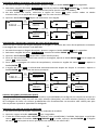
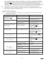
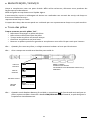
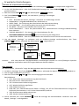
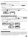
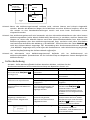
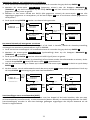
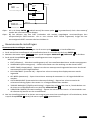
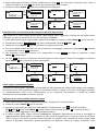
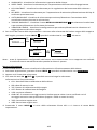
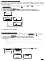
Main Menu
Main menu displays wrench operational information.
1. From target torque or angle screen, press and hold ENTER button for 3 seconds.
2. Use UP /DOWN buttons to highlight menu selection then press ENTER button.
Menu Selections:
EXIT - Exits Main menu and returns to target screen.
SET HEAD LENGTH - Displays wrench head length entry screen.
SHOW DATA - Displays stored torque and angle data.
CLEAR DATA - Clears stored torque and angle data.
CYCLE COUNT - Displays torque/angle cycle count screen.
SETTINGS - Displays advanced settings menu (see Advanced Settings Section).
CONFIGURE - Displays advanced configuration menu (see Advanced Configuration Section).
3. To exit Main menu and return to target torque or angle screen, press ENTER button while EXIT
menu selection is highlighted.
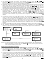
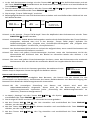
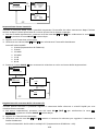
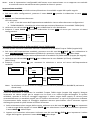
Setting Head Length
Note: If an adapter or extension is added to wrench, length of adapter/extension being used can be
entered to correct for a different length than head used to calibrate wrench without requiring
re-calibration.
1. To enter a head length, from target torque or angle screen, press and hold ENTER button for 3
seconds.
2. With SET HEAD LENGTH menu selection highlighted, momentarily press ENTER button.
3. Set Head Length screen is displayed next. Default head length is length of head at calibration. Use
UP /DOWN buttons to increment/decrement head length.
4. Pressing and holding UP /DOWN buttons will progressively increment/decrement value
faster. Pressing UP and DOWN buttons simultaneously will reset head length to zero.
5. Default units of length is in inches. Press UNITS U button to change to millimeters.
6. Pressing ENTER button after length is set returns to main menu. If length is changed from
default, "OFFSET IN USE" message will be displayed on target screen.
00
M 100.0 FT-LB
EXIT
SET HEAD LENGTH
SHOW DATA
M CLEAR DATA
ENTER
button
held
Target Screen
Main menu
01
M 180 DEG
MEMORY ICON
MODE CYCLE
COUNT

6
Note: Head length entered is offset length measured from center of drive to center of fastener.
Use of Negative Offsets
Note: Enter a negative value for offset when used in reverse direction.
When length of an offset is negative, maximum fastener target is limited by following formulas:
240 in-lb wrench:
Maximum Target Torque =
offset * 24 + 240
100 ft-lb wrench:
Maximum Target Torque =
offset * 8 + 100
250 ft-lb wrench:
Maximum Target Torque =
offset * 12 + 250
Offset
Max Target
Offset
Max Target
Offset
Max Target
-1"
216 in-lb
-1"
92 ft-lb
-1"
238 ft-lb
-2"
192 in-lb
-2"
84 ft-lb
-2"
226 ft-lb
-3"
168 in-lb
-3"
76 ft-lb
-3"
214 ft-lb
-4"
144 in-lb
-4"
68 ft-lb
-4"
202 ft-lb
Note: When using a negative offset, entering a target torque greater than maximum values above
may cause an overtorque error before reaching fastener target torque and possibly damage
wrench.
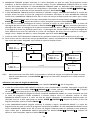
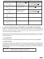
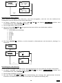
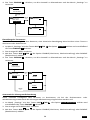
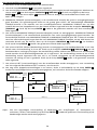
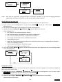
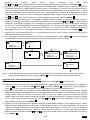
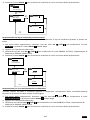
Viewing Stored Torque and Angle Data
Torque data is stored in memory after each torque cycle if applied torque has reached target value.
Torque and angle data is stored in memory after each angle cycle if applied angle has reached target
value. Memory Indicator is displayed when data is stored in non-volatile memory.
1. To view stored torque and angle data, from target torque or angle screen, press and hold ENTER
button for 3 seconds.
2. Highlight SHOW DATA menu selection by pressing UP /DOWN buttons then press
ENTER button to display Show Data screen.
00
M 100.0 FT-LB
00
OFFSET IN USE
M 100.0 FT-LB
ENTER button (after length change)
EXIT
SET HEAD LENGTH
SHOW DATA
M CLEAR DATA
SET HEAD LENGTH
M 0.000 IN
M
ENTER
button
held
Target Screen
ENTER
button
UP/DOWN buttons
UNITS
button
SET HEAD LENGTH
M 0.0 MM
M
UP/DOWN buttons

7
3. In Show Data screen, scroll through each stored data record by pressing UP /DOWN
buttons.
Example: 02 = Show Data List Counter: TQ = Peak torque value
01 = Show Data List Counter: TQ = Peak torque value: ANG = Peak angle value
4. Pressing ENTER button while on Show Data screen returns to main menu.
Note: A maximum of 50 data records can be stored in memory. Memory full icon will be displayed
when full. New data will replace oldest record until memory is cleared.
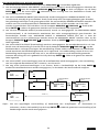
Deleting Stored Torque and Angle Data
1. From target torque or angle screen, press and hold ENTER button for 3 seconds.
2. Highlight CLEAR DATA menu selection using UP /DOWN buttons then press ENTER
button to display CLEAR ALL DATA screen.
3. In CLEAR ALL DATA screen, highlight YES menu selection to delete all stored data, or NO menu
selection to exit without deleting data.
4. Press ENTER button after making selection.
Viewing and Clearing Wrench Cycle Counter
Each time torque or angle target is reached, wrench cycle counter is incremented. Maximum cycle
count is 999999.
1. From target torque or angle screen, press and hold ENTER button for 3 seconds.
2. Highlight CYCLE COUNT menu selection using UP /DOWN buttons.
3. Press ENTER button to display CYCLES screen.
4. To exit CYCLE COUNT screen without clearing count, press ENTER button while EXIT menu
selection is highlighted.
5. To reset wrench cycle count to 0, highlight CLEAR menu selection then press ENTER button.
6. EXIT menu selection is automatically highlighted after count is cleared. Press ENTER button to
return to main menu.
00
M 100.0 FT-LB
02: 15:40:15
2013/06/26
TQ: 14.2 FT-LBS
M
EXIT
SET HEAD LENGTH
SHOW DATA
M CLEAR DATA
OR
UP/DOWN buttons
If clock has been
set data
timestamp will
be displayed
(see Advanced
Configuration).
01: 15:35:05
2013/03/26
TQ: 15.3 FT-LBS
M ANG 84 DEG
01:
TQ: 15.3 FT-LBS
M ANG 84 DEG
EXIT
SET HEAD LENGTH
SHOW DATA
M CLEAR DATA
02:
TQ: 14.2 FT-LBS
M
ENTER
button
held
Target Screen
ENTER
button
UP/DOWN buttons
OR
00
M 100.0 FT-LB
EXIT
SET HEAD LENGTH
SHOW DATA
CLEAR DATA
EXIT
SET HEAD LENGTH
SHOW DATA
M CLEAR DATA
EXIT
SET HEAD LENGTH
SHOW DATA
M CLEAR DATA
CLEAR ALL DATA
YES
M NO
CLEAR ALL DATA
YES
M NO
EXIT
SET HEAD LENGTH
SHOW DATA
M CLEAR DATA
ENTER
button
held
Target Screen
ENTER
button
UP/DOWN buttons
UP/DOWN buttons
ENTER
button
ENTER
button

8
Target Presets (PSET)
PSET function gives user ability to configure 10 preset target torque or target angle settings, each
with a minimum (target), maximum (over range) and batch count value. PSETs are stored in non-
volatile memory so that they are retained while power is off.
Adding a Torque Preset
1. From target torque screen, select units of measure.
2. Press and hold UNITS U button for 3 seconds.
3. ADD PRESET confirmation screen is displayed. Highlight YES menu selection using UP /DOWN
buttons then press ENTER button. NO menu selection returns to main menu without adding
a PSET.
4. MINIMUM TORQUE is target value at which green progress lights, audible alert and vibrator turn
on. Initial MINIMUM TORQUE value is value from target torque screen. MINIMUM TORQUE can
be set to any value within wrench torque range by pressing UP /DOWN buttons. Once
desired target torque value has been set, press ENTER button.
5. MAXIMUM TORQUE screen is displayed next. MAXIMUM TORQUE is torque value above which
red progress lights turn on. Initial MAXIMUM TORQUE value will be MINIMUM TORQUE plus 4%.
Maximum torque value can be set greater than MINIMUM TORQUE value to 10% above wrench
maximum range by pressing UP /DOWN buttons. Once desired value has been set, press
ENTER button.
6. BATCH COUNT screen is displayed next. Default value is zero. Batch count range is 0 to 99. Press
UP /DOWN buttons to increment/decrement batch count. Mode Count increments each
time target torque is reached if a batch count of zero is entered. Mode Count decrements if a
non-zero batch count is entered and resets to batch count value when count reaches zero. Once
desired value has been set, press ENTER button.
7. PSET target screen is displayed labeled with next available PSET number from 01 to 10.
8. To enter additional torque presets, repeatedly press ENTER button until target torque screen
is displayed and repeat steps above.
BATCH COUNT
3
ENTER
button
UP/DOWN buttons
ADD PRESET
YES
NO
ADD PRESET
YES
NO
00
100.0 FT-LB
UNIT
button
held
Target Torque Screen
ENTER
button
UP/DOWN buttons
UP/DOWN buttons
ENTER
button
ENTER button
MINIMUM TORQUE
100.0 FT-LB
MAXIMUM TORQUE
104.0 FT-LB
PSET 01 03
100.0 FT-LB
Preset Torque Screen
UP/DOWN buttons
ENTER button
SET HEAD LENGTH
SHOW DATA
CLEAR DATA
M CYCLE COUNT
00
M 100.0 FT-LB
CYCLES: 12
CLEAR
M EXIT
CYCLES: 12
CLEAR
M EXIT
SET HEAD LENGTH
SHOW DATA
CLEAR DATA
M CYCLE COUNT
EXIT
SET HEAD LENGTH
SHOW DATA
M CLEAR DATA
ENTER
button
held
Target Screen
ENTER
button
UP/DOWN buttons
UP/DOWN buttons
ENTER
button
ENTER
button
CYCLES: 0
CLEAR
M EXIT
ENTER button

9
Note: To select a stored PSET or manual target torque or angle mode, repeatedly press ENTER
button until desired PSET or manual mode is displayed.
Adding an Angle Preset
1. From target angle screen, press and hold UNITS U button for 3 seconds.
2. ADD PRESET confirmation screen is displayed. Highlight YES menu selection using UP /DOWN
buttons then press ENTER button. NO menu selection returns to main menu without
adding a PSET.
3. MINIMUM ANGLE screen is displayed. MINIMUM ANGLE is target value at which green progress
lights, audible alert and vibrator turn on. Initial MINIMUM ANGLE value is value from target angle
screen. MINIMUM ANGLE can be set from 0 to 360° by pressing UP /DOWN buttons. Once
desired target angle value has been set, press ENTER button.
4. MAXIMUM ANGLE screen is displayed next. MAXIMUM ANGLE is angle value above which red
progress lights turn on. Initial MAXIMUM ANGLE value will be MINIMUM ANGLE plus 4%.
Maximum angle value can be set to any value greater than MINIMUM ANGLE by pressing
UP /DOWN buttons. Once desired value has been set, press ENTER button.
5. BATCH COUNT screen is displayed next. Default value is zero. Batch count range is 0 to 99. Press
UP /DOWN buttons to increment/decrement batch count. Mode Count increments each
time target angle is reached if a batch count of zero is entered. Mode Count decrements if a non-
zero batch count is entered and resets to batch count value when count reaches zero. Once
desired value has been set, press ENTER button.
6. PSET target screen is displayed labeled with next available PSET number from 01 to 10.
7. To enter additional angle presets, repeatedly press ENTER button until target angle screen is
displayed and repeat steps above.
Note: To select a stored PSET or manual target torque or angle mode, repeatedly press
ENTER button until desired PSET or manual mode is displayed.
Editing a Preset
Edit PSET function gives user ability to edit stored PSETS on wrench.
1. From Preset screen to be edited, press and hold UNITS U button for 3 seconds.
2. CHANGE PRESET screen is displayed.
3. Highlight EDIT selection using UP /DOWN buttons then press ENTER button.
4. MINIMUM TORQUE or ANGLE screen is displayed. Value can be changed by pressing UP
/DOWN buttons. Once desired target torque or angle value has been set, press ENTER
button.
BATCH COUNT
4
UP/DOWN buttons
ENTER
button
ADD PRESET
YES
NO
ADD PRESET
YES
NO
00
90 DEG
UNIT
button
held
Target Angle Screen
ENTER
button
UP/DOWN buttons
UP/DOWN buttons
ENTER
button
ENTER button
MINIMUM ANGLE
90 DEG
MAXIMUM ANGLE
94 DEG
PSET 02 04
90 DEG
Preset Angle Screen
UP/DOWN buttons
ENTER button

10
5. MAXIMUM TORQUE or ANGLE screen is displayed next . Value can be changed by pressing UP
/DOWN buttons. Once desired target torque or angle value has been set, press
ENTER button.
6. BATCH COUNT screen is displayed next. Value can be changed by pressing UP /DOWN
buttons. Once desired batch count value has been set, press ENTER button.
7. PSET target screen is displayed labeled with same PSET number.
Note: Pressing ENTER button while EXIT menu selection is highlighted will exit without editing
PSET.
Deleting a Preset
Delete PSET function allows user to remove stored presets from wrench.
1. From Preset screen to be deleted, press and hold UNITS U button for 3 seconds.
2. CHANGE PRESET screen is displayed.
3. Highlight DELETE menu selection using UP /DOWN buttons and press ENTER button.
4. Target screen is displayed and deleted PSET is no longer available for selection.
Note: Pressing ENTER button while EXIT menu selection is highlighted will exit without deleting
PSET.
Note: When a PSET is deleted, all other stored PSET’s will retain their original PSET numbers. When
a new PSET is entered, it will be assigned first available PSET number in sequence.
BATCH COUNT
0
ENTER
button
UP/DOWN buttons
CHANGE PRESET
DELETE
EDIT
EXIT
PSET 02 00
92 DEG
UNIT
button
held
Preset Angle Screen
UP/DOWN buttons
ENTER button
PSET 02 00
90 DEG
Preset Angle Screen
CHANGE PRESET
DELETE
EDIT
EXIT
ENTER
button
UP/DOWN buttons
MINIMUM ANGLE
92 DEG
MAXIMUM ANGLE
94 DEG
UP/DOWN buttons
ENTER
button
00
100.0 FT-LB
CHANGE PRESET
DELETE
EDIT
EXIT
UNIT
button
held
Target Screen
UP/DOWN buttons
ENTER button
PSET 02 00
92 DEG
Preset Angle Screen
CHANGE PRESET
DELETE
EDIT
EXIT
ENTER button

11
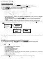
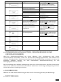
Advanced Settings
Accessing Advanced Settings
Advanced settings are accessed from SETTINGS menu selection on main menu.
1. From target torque or angle screen, press and hold ENTER button for 3 seconds.
2. Highlight SETTINGS menu selection using UP /DOWN buttons.
3. Press ENTER button to display Settings menu.
Menu Selections:
EXIT - Exits Settings menu and returns to target screen.
SHOW INFO - Displays wrench operational information.
SLEEP TIME - Displays power down interval setup screen.
LCD CONTRAST - Displays LCD contrast setup screen.
KEY BEEP - Displays button press beep enable/disable setup screen.
AUTO BACKLIGHT - Displays auto backlight enable/disable screen to turn on backlight
during measurement.
TOGGLE BACKLGHT - Displays BACKLIGHT button toggle or timeout enable/disable
screen.
VIBRATOR CONFIG - Displays vibrator ON/OFF configuration for when target reached.
4. To exit Settings menu and return to target torque or angle screen, press ENTER button while
EXIT menu selection is highlighted.
Note: All user configurable settings are stored in non-volatile memory and are retained while power
is off.
Show Info
Show Info menu selection displays wrench operational information.
1. From Settings menu, press ENTER button while SHOW INFO selection is highlighted.
2. SHOW INFO screen is displayed.
3. UP /DOWN buttons are used to scroll screen.
Operational Information:
CAL: Date of last wrench calibration.
ISD: In-Service Date.
TCF: Torque Calibration Factor.
ACF: Angle Calibration Factor.
VER: Software version.
OVR CNT: Overtorque Counter tracks how many times an over-torque event occurred on
wrench (torque >125% of full scale).
TQZ: Torque Zero Offset.
ANZ: Angle Zero Offset.
4. Pressing ENTER button exits Show Info screen and returns to Settings menu.
Settings menu
00
100.0 FT-LB
Target Screen
SHOW DATA
CLEAR DATA
CYCLE COUNT
SETTINGSs
UP/DOWN buttons
ENTER
button
EXIT
SET HEAD LENGTH
SHOW DATA
CLEAR DATA
ENTER
button
held
EXIT
SHOW INFO
SLEEP TIME
LCD CONTRAST

12
Setting Sleep Time
This function will allow user to set interval wrench enters power-down state following last applied
torque or button press.
1. From Settings menu, use UP /DOWN buttons to highlight SLEEP TIME selection then press
ENTER button.
2. SLEEP TIME screen is displayed.
3. Use UP /DOWN buttons to select sleep interval.
Selectable Intervals:
2 MIN (factory default)
5 MIN
10 MIN
30 MIN
1 HR
2 HR
8 HR
4. Press ENTER button to accept selection and exit to Settings menu.
Setting LCD Contrast
This function will allow user to set LCD contrast for optimal viewing.
1. From Settings menu, use UP /DOWN buttons to highlight LCD CONTRAST selection then
press ENTER button.
2. CONTRAST screen is displayed.
ENTER
button
CAL: 2013/01/01
ISD: 2013/01/01
TCF: 14800
ACF: 1257
EXIT
SHOW INFO
SLEEP TIME
LCD CONTRAST
ENTER
button
VER: 1.0
OVR CNT: 0
TQZ: -1539
ANZ: 8196
UP/DOWN buttons
EXIT
SHOW INFO
SLEEP TIME
LCD CONTRAST
UP/DOWN buttons
ENTER
button
SLEEP TIME
2 MIN
EXIT
EXIT
SHOW INFO
SLEEP TIME
LCD CONTRAST
ENTER
button
UP/DOWN buttons
SLEEP TIME
8 HR
EXIT

13
3. Use UP /DOWN buttons while viewing display to change contrast to desired level.
Selectable levels: 20 to 80 in increments of 5 (factory default = 40).
4. Press ENTER button to accept selection and exit to Settings menu.
Key Beep Setup
This function will allow user to enable or disable audio feedback when a button is pressed.
1. From Settings menu, use UP /DOWN buttons to highlight KEY BEEP selection then press
ENTER button.
2. KEY BEEP screen is displayed.
3. Use UP /DOWN buttons to highlight ENABLE (factory default) or DISABLE selection.
4. Press ENTER button to accept selection and exit to Settings menu.
Auto Backlight Setup
This function will allow user to enable or disable backlight from turning on during torque or angle
measurement.
1. From Settings menu, use UP /DOWN buttons to highlight AUTO BACKLIGHT selection then
press ENTER button.
2. AUTO BACKLIGHT screen is displayed.
3. Use UP /DOWN buttons to highlight ENABLE (factory default) or DISABLE selection.
4. Press ENTER button to accept selection and exit to Settings menu.
EXIT
SHOW INFO
SLEEP TIME
LCD CONTRAST
UP/DOWN buttons
ENTER
button
KEY BEEP
ENABLE
DISABLE
SHOW INFO
SLEEP TIME
LCD CONTRAST
KEY BEEP
ENTER
button
UP/DOWN buttons
KEY BEEP
ENABLE
DISABLE
EXIT
SHOW INFO
SLEEP TIME
LCD CONTRAST
UP/DOWN buttons
ENTER
button
CONTRAST: 20
EXIT
SHOW INFO
SLEEP TIME
LCD CONTRAST
ENTER
button
UP/DOWN buttons
CONTRAST: 80

14
Toggle Backlight Setup
This function will allow user to enable or disable backlight toggle function. If toggle mode is disabled,
BACKLIGHT button turns on backlight and it automatically turns off after five seconds following
any last button press. If toggle mode is enabled, a BACKLIGHT button press will turn on backlight
and it will remain on until next BACKLIGHT button press.
1. From Settings menu, use UP /DOWN buttons to highlight TOGGLE BACKLGHT selection
then press ENTER button.
2. TOGGLE BACKLGHT screen is displayed.
3. Use UP /DOWN buttons to highlight ENABLE or DISABLE (factory default) selection.
4. Press ENTER button to accept selection and exit to Settings menu.
Note: Backlight will turn off when wrench powers down either by POWER q button press or sleep
time.
Note: If toggle backlight is enabled and backlight is on, backlight will remain on during and after
applying torque.
EXIT
SHOW INFO
SLEEP TIME
LCD CONTRAST
UP/DOWN buttons
ENTER
button
AUTO BACKLIGHT
ENABLE
DISABLE
SLEEP TIME
LCD CONTRAST
KEY BEEP
AUTO BACKLIGHT
ENTER
button
UP/DOWN buttons
AUTO BACKLIGHT
ENABLE
DISABLE
EXIT
SHOW INFO
SLEEP TIME
LCD CONTRAST
UP/DOWN buttons
ENTER
button
TOGGLE BACKLGHT
ENABLE
DISABLE
LCD CONTRAST
KEY BEEP
AUTO BACKLIGHT
TOGGLE BACKLGHT
ENTER
button
UP/DOWN buttons
TOGGLE BACKLGHT
ENABLE
DISABLE

15
Vibrator Configuration
This function will allow user to configure vibrator for On or Off when target is reached for preference
and/or battery power savings.
1. From Settings menu, use UP /DOWN buttons to highlight VIBRATOR CONFIG selection then
press ENTER button.
2. VIBRATOR CONFIG screen is displayed.
3. Use UP /DOWN buttons to toggle ON or OFF selection.
4. Press ENTER button to accept selection and exit to Settings menu.
Advanced Configuration
Accessing Advanced Configuration
Advanced configuration is accessed from CONFIGURE menu selection on main menu.
1. From target torque or angle screen, press and hold ENTER button for 3 seconds.
2. Highlight CONFIGURE menu selection using UP /DOWN buttons.
3. Press ENTER button to display Configure menu.
Menu Selections:
EXIT - Exits Configure menu and returns to target torque or angle screen.
MODE SETUP - Displays wrench mode setup menu.
CALIBRATION - Displays wrench calibration menu (password protected).
SET DATE/TIME - Displays clock date and time entry screens.
SET CAL INTRVAL - Displays calibration interval setup screen (requires clock date and time
setup).
4. To exit Configure menu and return to target torque or angle screen, press ENTER button while
EXIT menu selection is highlighted.
00
100.0 FT-LB
Target Screen
CLEAR DATA
CYCLE COUNT
SETTINGS
CONFIGUREs
UP/DOWN buttons
EXIT
MODE SETUPs
CALIBRATION
SET DATE/TIME
EXIT
SET HEAD LENGTH
SHOW DATA
CLEAR DATA
ENTER
button
held
ENTER
button
Configure menu
EXIT
SHOW INFO
SLEEP TIME
LCD CONTRAST
UP/DOWN buttons
ENTER
button
VIBRATOR CONFIG
ON
EXIT
ENTER
button
UP/DOWN buttons
VIBRATOR CONFIG
OFF
EXIT
KEY BEEP
AUTO BACKLIGHT
TOGGLE BACKLGHT
VIBRATOR CONFIG

16
Note: All user configurable settings are stored in non-volatile memory and are retained while power
is off.
Mode Setup
Mode setup menu allows user to enable/disable Torque THEN angle mode.
1. From Configure menu, press ENTER button while MODE SETUP selection is highlighted.
2. Mode Setup menu is displayed.
Menu Selections:
EXIT - Exits Mode setup menu and returns to Configure menu screen.
THEN DISABLED - Displays THEN Mode enable/disable screen.
3. Use UP /DOWN buttons to highlight menu selections.
4. Press ENTER button while EXIT menu selection is highlighted to return to Configure menu.
Enable/Disable Torque THEN Angle Mode
This function will allow user to enable or disable Torque THEN Mode.
1. From Mode Setup menu, use UP /DOWN buttons to highlight THEN DISABLED selection
(factory default) then press ENTER button.
2. TQ THEN ANGLE enable/disable screen is displayed.
3. Use UP /DOWN buttons to select ENABLE or DISABLE selection.
4. Press ENTER button to accept selection and exit to Mode Setup menu.
Note: Menu selection indicates current configuration (ENABLED or DISABLED).
Torque THEN Angle Mode
Torque THEN Angle mode is setup by first setting a target torque and units then a target angle before
selecting Torque THEN Angle mode. In Torque THEN Angle mode, when applied torque reaches
target torque, wrench automatically switches to angle mode for angle measurement. Progress lights
indicate applied torque progress while torque is measured and angle when angle is measured.
1. From target torque screen, use UP /DOWN buttons to set target torque and UNITS U
button to select torque measurement units then press ENTER button.
2. Angle target screen is displayed. Use UP /DOWN buttons to set target angle then press
ENTER button.
3. Torque THEN Angle mode screen is displayed.
4. Apply torque until target is reached then rotate wrench to target angle.
EXIT
THEN DISABLED
EXIT
MODE SETUPs
CALIBRATION
SET DATE/TIME
ENTER
button
Configure menu
Mode Setup menu
EXIT
THEN DISABLED
TQ THEN ANGLE
ENABLE
DISABLE
ENTER
button
UP/DOWN buttons
TQ THEN ANGLE
ENABLE
DISABLE
ENTER
button
ENTER
button
EXIT
THEN ENABLED
EXIT
THEN DISABLED

17
Note: UNITS U button can be used to select torque units while on Torque THEN Angle screen.
Note: Torque THEN Angle Presets are entered by pressing and holding Units button while on
Torque THEN Angle screen. Refer to "Adding a Torque Preset" and "Adding an Angle
Preset" in Basic section for parameter entry.
Note: Torque cycle is not recorded in memory unless both torque and angle reach targets.
Note: Red and yellow progress lights turn on if torque exceeds 110% of wrench full scale or if
angle exceeds target plus 4% in manual mode.
Note: Red and yellow progress lights turn on if torque exceeds maximum torque or if angle
exceeds maximum angle in Preset mode.
Calibration
Calibration menu is password protected. Contact your local Snap-on
Repair Center regarding Calibration menu.
Setting Date and Time
Set Date/Time function allows user to set real-time-clock date and time for time stamping data
records, recording last calibration date and notifying user of an expired calibration interval.
Note: When date and time is set for first time, In-Service date is also set and is used for calculating
initial calibration interval (see "Setting Calibration Interval" in Advanced Configuration
section).
1. From Configure menu, use UP /DOWN buttons to highlight SET DATE/TIME selection then
press ENTER button.
2. SET DATE screen is displayed with year highlighted.
3. Use UP /DOWN buttons to set year then press ENTER button to highlight month.
4. Use UP /DOWN buttons to set month then press ENTER button to highlight day.
5. Use UP /DOWN buttons to set day then press ENTER button.
6. SET TIME screen is displayed with Hour highlighted.
7. Use UP /DOWN buttons to set hour then press ENTER button to highlight minutes.
8. Use UP /DOWN buttons to set minutes then press ENTER button to highlight seconds.
9. Use UP /DOWN buttons to set seconds then press ENTER button.
10. Clock is set and Configure menu is displayed.
EXIT
MODE SETUP
CALIBRATION
SET DATE/TIME
00
100.0 FT-LB
ENTER
button
Torque THEN Angle Screen
UP/DOWN buttons
00
45 DEG
UP/DOWN buttons
ENTER
button
00
TQ: 100.0 FT-LB
THEN AN: 45 DEG

18
Note: Year selection will scroll up from 2013. Month selection will scroll from 1 to 12. Day selection
will scroll from 1 to 31.
Note: Hour selection will scroll through 0 to 23. Minute and Second selections will scroll through 0 to
59.
Note: If batteries are removed from wrench for longer than 20 minutes, clock will revert to default
settings and must be re-entered at power on.
Setting Calibration Interval
This function will allow user to set calibration interval for when "CAL NEEDED" message will be
displayed.
1. From Configure menu, use UP /DOWN buttons to highlight SET CAL INTRVAL selection then
press ENTER button.
2. CAL INTERVAL screen is displayed.
3. Use UP /DOWN buttons to change calibration interval.
Selectable Intervals:
DISABLED (factory default)
3 MON
6 MON
12 MON
4. Press ENTER button to accept selection and exit to Configure menu.
Note: Clock Date and Time must be set before calibration interval will function. If batteries are
removed from wrench for longer than 20 minutes, clock will revert to default settings and must
be re-entered at power on.
ENTER
button
CAL INTRVAL
DISABLED
EXIT
MODE SETUP
CALIBRATION
SET DATE/TIME
SET CAL INTRVAL
ENTER
button
UP/DOWN buttons
CAL INTRVAL
12 MON
EXIT
SET DATE
2013/01/01
YR MON DAY
SET DATE
2013/01/01
YR MON DAY
SET DATE
2013/01/01
YR MON DAY
EXIT
MODE SETUP
CALIBRATION
SET DATE/TIME
ENTER
button
UP/DOWN buttons
ENTER
button
UP/DOWN buttons
ENTER
button
UP/DOWN buttons
SET TIME
12 : 00 : 00
HR MIN SEC
SET TIME
12 : 00 : 00
HR MIN SEC
SET TIME
12 : 00 : 00
HR MIN SEC
UP/DOWN buttons
ENTER
button
UP/DOWN buttons
ENTER
button
UP/DOWN buttons
ENTER button
ENTER button

19
Note: Calibration interval is calculated from either In-Service Date or last Calibration date (see SHOW
INFO menu) depending on which is more recent date. When clock Date is greater than In-
Service or Last Calibration date, plus Cal Interval, "CAL NEEDED" message will be displayed on
power up and after a re-zero. Pressing ENTER button will continue to target menu. Applying
torque while "CAL NEEDED" message is displayed will immediately display torque or angle
measurement and return to target menu when released.
Note: As an alternative to calibration interval, a Calibration Cycle Counter is provided in Calibration
menu (Contact your local Snap-on Repair Center regarding Calibration menu).
Troubleshooting
Note: If any of following issues persist, return wrench to an authorized Snap-on repair center.
Issue
Possible Cause
Resolution
Wrench does not turn on
when POWER q button
pressed
Dead/No batteries
Replace batteries
Software glitch
Cycle power using end-cap
Torque reading out of spec
Calibration required
Recalibrate
Incorrect head length entered
Enter correct offset head length
Wrench did not retain settings
while batteries were removed
Batteries removed before
settings were saved in non-
volatile memory.
Clear data, re-enter settings and
press and hold POWER q
button to power down wrench
before removing batteries
Torque or angle displayed
while no torque applied
Torque or angle zeroed while
torque applied
Place wrench on stable surface
with no torque applied and
press POWER q button to re-
zero wrench
Low battery
Press ENTER button to
continue using wrench and
replace batteries soon
Dead battery
Press POWER q button to turn
off wrench and replace batteries
Torque applied while zeroing
Remove torque and re-zero
Wrench over torqued
Recalibrate
Wrench improperly calibrated
Recalibrate
Torque sensor failure
Return to Snap-on Repair Center
Wrench moving during
zeroing
Place wrench on stable surface
Gyro unstable
Return to Snap-on Repair Center
POWER q button pressed
during angle zeroing (Aborted
zeroing to access menus)
Place wrench on stable surface
and press POWER q button to
re-zero
Over 125% of full scale torque
applied
Cycle power using POWER q
button and recalibrate
Wrench rotated too fast
during angle measurement
Place wrench on stable surface
and press POWER q button to
re-zero
La pagina si sta caricando...
La pagina si sta caricando...
La pagina si sta caricando...
La pagina si sta caricando...
La pagina si sta caricando...
La pagina si sta caricando...
La pagina si sta caricando...
La pagina si sta caricando...
La pagina si sta caricando...
La pagina si sta caricando...
La pagina si sta caricando...
La pagina si sta caricando...
La pagina si sta caricando...
La pagina si sta caricando...
La pagina si sta caricando...
La pagina si sta caricando...
La pagina si sta caricando...
La pagina si sta caricando...
La pagina si sta caricando...
La pagina si sta caricando...
La pagina si sta caricando...
La pagina si sta caricando...
La pagina si sta caricando...
La pagina si sta caricando...
La pagina si sta caricando...
La pagina si sta caricando...
La pagina si sta caricando...
La pagina si sta caricando...
La pagina si sta caricando...
La pagina si sta caricando...
La pagina si sta caricando...
La pagina si sta caricando...
La pagina si sta caricando...
La pagina si sta caricando...
La pagina si sta caricando...
La pagina si sta caricando...
La pagina si sta caricando...
La pagina si sta caricando...
La pagina si sta caricando...
La pagina si sta caricando...
La pagina si sta caricando...
La pagina si sta caricando...
La pagina si sta caricando...
La pagina si sta caricando...
La pagina si sta caricando...
La pagina si sta caricando...
La pagina si sta caricando...
La pagina si sta caricando...
La pagina si sta caricando...
La pagina si sta caricando...
La pagina si sta caricando...
La pagina si sta caricando...
La pagina si sta caricando...
La pagina si sta caricando...
La pagina si sta caricando...
La pagina si sta caricando...
La pagina si sta caricando...
La pagina si sta caricando...
La pagina si sta caricando...
La pagina si sta caricando...
La pagina si sta caricando...
La pagina si sta caricando...
La pagina si sta caricando...
La pagina si sta caricando...
La pagina si sta caricando...
La pagina si sta caricando...
La pagina si sta caricando...
La pagina si sta caricando...
La pagina si sta caricando...
La pagina si sta caricando...
La pagina si sta caricando...
La pagina si sta caricando...
La pagina si sta caricando...
La pagina si sta caricando...
La pagina si sta caricando...
La pagina si sta caricando...
La pagina si sta caricando...
La pagina si sta caricando...
La pagina si sta caricando...
La pagina si sta caricando...
La pagina si sta caricando...
La pagina si sta caricando...
La pagina si sta caricando...
La pagina si sta caricando...
La pagina si sta caricando...
La pagina si sta caricando...
La pagina si sta caricando...
La pagina si sta caricando...
La pagina si sta caricando...
La pagina si sta caricando...
La pagina si sta caricando...
La pagina si sta caricando...
La pagina si sta caricando...
La pagina si sta caricando...
La pagina si sta caricando...
La pagina si sta caricando...
La pagina si sta caricando...
La pagina si sta caricando...
La pagina si sta caricando...
La pagina si sta caricando...
-
 1
1
-
 2
2
-
 3
3
-
 4
4
-
 5
5
-
 6
6
-
 7
7
-
 8
8
-
 9
9
-
 10
10
-
 11
11
-
 12
12
-
 13
13
-
 14
14
-
 15
15
-
 16
16
-
 17
17
-
 18
18
-
 19
19
-
 20
20
-
 21
21
-
 22
22
-
 23
23
-
 24
24
-
 25
25
-
 26
26
-
 27
27
-
 28
28
-
 29
29
-
 30
30
-
 31
31
-
 32
32
-
 33
33
-
 34
34
-
 35
35
-
 36
36
-
 37
37
-
 38
38
-
 39
39
-
 40
40
-
 41
41
-
 42
42
-
 43
43
-
 44
44
-
 45
45
-
 46
46
-
 47
47
-
 48
48
-
 49
49
-
 50
50
-
 51
51
-
 52
52
-
 53
53
-
 54
54
-
 55
55
-
 56
56
-
 57
57
-
 58
58
-
 59
59
-
 60
60
-
 61
61
-
 62
62
-
 63
63
-
 64
64
-
 65
65
-
 66
66
-
 67
67
-
 68
68
-
 69
69
-
 70
70
-
 71
71
-
 72
72
-
 73
73
-
 74
74
-
 75
75
-
 76
76
-
 77
77
-
 78
78
-
 79
79
-
 80
80
-
 81
81
-
 82
82
-
 83
83
-
 84
84
-
 85
85
-
 86
86
-
 87
87
-
 88
88
-
 89
89
-
 90
90
-
 91
91
-
 92
92
-
 93
93
-
 94
94
-
 95
95
-
 96
96
-
 97
97
-
 98
98
-
 99
99
-
 100
100
-
 101
101
-
 102
102
-
 103
103
-
 104
104
-
 105
105
-
 106
106
-
 107
107
-
 108
108
-
 109
109
-
 110
110
-
 111
111
-
 112
112
-
 113
113
-
 114
114
-
 115
115
-
 116
116
-
 117
117
-
 118
118
-
 119
119
-
 120
120


in altre lingue
- English: Snap-On TECHANGLE User manual
- Deutsch: Snap-On TECHANGLE Benutzerhandbuch
- Nederlands: Snap-On TECHANGLE Handleiding
- português: Snap-On TECHANGLE Manual do usuário
Altri documenti
-
Sioux Tools TC50A Series Instructions Manual
-
Beta 599DGT-AN Istruzioni per l'uso
-
Ingersoll-Rand ETW-E75 Manuale utente
-
MULTIPLEX Royal Sx 16 Elegance Manuale del proprietario
-
USAG 814 A 135 Manuale utente
-
Spirit JOHNNY G SPIRIT BIKE Manuale del proprietario
-
Star Trac Ion Computer Manuale del proprietario
-
Furuno GP1971F Manuale utente
-
Festo 8061196 Operating Instructions Manual
-
Star Trac S Series Recumbent S-RBx Manuale del proprietario