
User Manual
Bedienungsanleitung
Manuel d’U lisa on
Manuale Utente
Manual del usuario
Brugermanual
Brukermanual
Användarhandledning
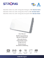
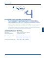
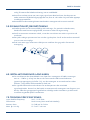
Satellite Antenna with integrated Single LNB SlimSat SA61
Satellite Antenna with integrated Twin LNB SlimSat SA62
Satellite Antenna with integrated Quad LNB SlimSat SA64
Picture similar
Integrated
4 LNB
Easy
mounting
65 cm dish
identical
Portable~8 cm
thick
UL
TRA HD
Supplied by STRONG Austria
Represented by
STRONG Ges.m.b.H.
Franz-Josefs-Kai 1
1010 Vienna
Austria
Email: [email protected]

User Manual
Bedienungsanleitung
Manuel d’U lisa on
Manuale Utente
Manual del usuario
Brugermanual
Brukermanual
Användarhandledning
Satellite Antenna with integrated Single LNB SlimSat SA61
Satellite Antenna with integrated Twin LNB SlimSat SA62
Satellite Antenna with integrated Quad LNB SlimSat SA64
Picture similar
Integrated
4 LNB
Easy
mounting
65 cm dish
identical
Portable~8 cm
thick
ULTRA HD
Supplied by STRONG Austria
Represented by
STRONG Ges.m.b.H.
Franz-Josefs-Kai 1
1010 Vienna
Austria
Email: [email protected]

PART 1 • English
1
English
CONTENT
1.0 WHAT IS SLIMSAT? 2
2.0 SAFETY INSTRUCTIONS 2
3.0 HOW TO INSTALL? 3
3.1 Step 1: Where to install? 3
3.2 Step 2: Installation 4
3.3 Step 3: Connecting the antenna and the receiver 6
3.4 Step 4: Fine tuning and fixing the bracket 6
4.0 TROUBLESHOOTING CHECK LIST FOR INITIAL INSTALLATION 7
5.0 LOSS OF SIGNAL / RAIN FADE 8
6.0 INSTALLATION USING LONG CABLE 8
7.0 TECHNICAL SPECIFICATION 8
A.1 BOX CONTENT 9
A.2 APPENDIX

PART 1 • English
2
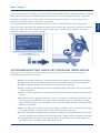
1.0 WHAT IS SLIMSAT?
SlimSat is a Horn Array Type Satellite Antenna with integrated LNB. It can receive signals from
major satellites and would replace a 65 cm parabolic dish. Small, discreet and easy to use, it can be
installed within a few minutes and used as a portable antenna for all satellite receptions. SlimSat
can be used for both Free-To-Air and encrypted (requiring an operator subscription) channel
reception; it can also receive all High Definition channels with a superior image quality. For use and
installation, please read the following instructions and installation materials carefully.
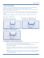
SlimSat SA61 with integrated Single LNB SlimSat SA62 with integrated Twin LNB
to connect to 1 satellite receiver to connect to 2 satellite receivers
SlimSat SA64 with integrated Quad LNB
to connect to 4 satellite receivers
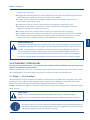
2.0 SAFETY INSTRUCTIONS
Before using this product, please read this user manual carefully and follow all
installation, mounting & orientation instructions exactly.
All instructions should be followed in order to avoid any technical problems.
Any electric or magnetic field close to the SlimSat may cause a bad reception or even cut
off the signal completely.
Do not drill the plastic cover of the antenna that seals the antenna from moisture.
Handle the antenna with care as any impact will cause damage to the electronics.
Do not open the cover, any reparation attempt by a non-qualified person can be
dangerous and void the warranty.
Any obstacle (buildings, trees, etc.) will block the reception of the signal from the satellite
to the antenna.
Do not paint or add any substance on the antenna cover, this will block the reception of
the signal from the satellite.

PART 1 • English
3
English
The cable between the antenna and the satellite receiver should not exceed 30 m as it will
decrease the quality of the signal.
The use of non- isolated jacks will result in a loss of the signal level.
Do not forget to adjust the antenna and the bracket to the cross-polarity (skew angle
please refer to chapter 3.4 step 4).
Tighten all the screws of the antenna once you have finished the adjustments.
This product contains the LNB, it is forbidden to add, change or modify the LNB.
For more precise details on the above points or for any information, please ask your
retailer or customer service.
Warning!!!
Antennas improperly installed to an inadequate structure are very susceptible to
wind damage. This damage can be very serious or even life threatening. The owner
and installer assumes full responsibility that the installation is structurally sound
to support all loads (weight, wind & ice) and properly sealed against leaks. The
manufacturer will not accept liability for any damage caused by a satellite system due
to the many unknown variable applications.
3.0 HOW TO INSTALL?
By following the instructions step by step you can proceed easily to install SlimSat by yourself or
with the help of a professional antenna installer.
Before installing your antenna check that the SlimSat box contains all items listed in the chapter
‘Box Content’. In the event of any missing parts, please contact your distributor.
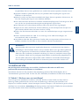
3.1 Step 1: Where to install?
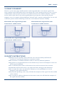
In order to receive a signal from the satellite, SlimSat is to be installed in an open loop space
(outside the house or the apartment), in the direction of the satellite towards the equator, for which
you will need a compass to exactly orient SlimSat toward the satellite.
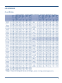
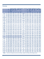
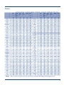
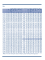
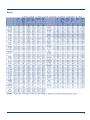
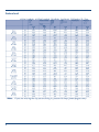
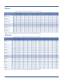
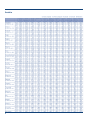
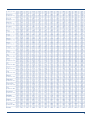
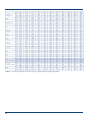
Note: Please refer to the table of the Azimuth angles specified in the back pages of this user manual.
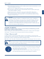
Note
To ensure accurate compass reading, stay away from large metal objects, specifically
electrical cables and then make multiple readings.
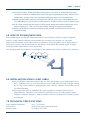
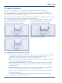
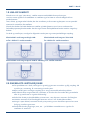
Make sure that there are no obstacles in front of SlimSat which can decrease the
signal reception quality, such as buildings, or trees (you may keep in mind that
trees will grow and may block the signal).
In order to be able to fix and install your antenna easily you might choose an
easily accessible place without any potential danger for installation.

PART 1 • English
4
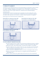
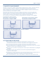
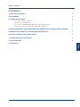
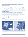
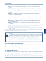
Think about the way you might pass your cable in a discreet way from the SlimSat to your satellite
receiver. The antenna should not be too distant from your satellite receiver; a cable longer than 30 m
can decrease the quality of the signal.
Bad Quality Signal Reception Good Quality Signal Reception
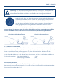
3.2 Step 2: Installation
In order to install your new antenna, you need to find the skew, elevation and azimuth angle by
referring to the table in the appendix of this user manual. If you can’t find your location, please
refer to the information of the place nearest to your location. This user manual will show you the
installation example for the reception of ASTRA1 satellite in Brest region of France.
The angle information for Brest region is Skew: -19.7º
El: 30º
Az: 149.6º
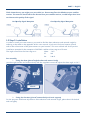
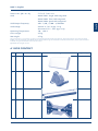
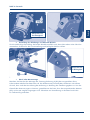
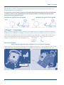
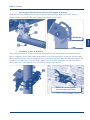
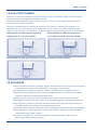
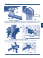
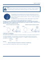
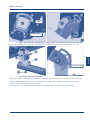
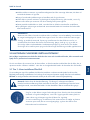
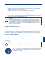
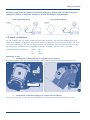
Part assembly
1. Fixing the skew (joint of angle bracket and antenna body)
Join the angle bracket and antenna body with the supplied screw and adjust the skew angle to -19.7
Check –
2. Fixing the elevation (joint of antenna body and main support)
For the purpose of delicate adjustment of the elevation and azimuth angle, please don’t fix the bolt
and nut tightly.

PART 1 • English
5
English
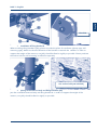
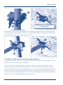
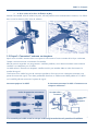
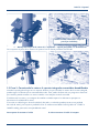
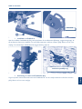
Check 30
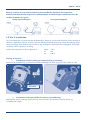
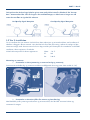
3. Installation of fixing bracket A
When installing fixing bracket A (B3), please consider the place of installation (clamp type, wall
mounting type). Make sure that the direction of the bracket is towards the satellite. In order to
support the weight of the antenna, nut (N1) should be fixed as tightly as possible. Please purchase
the anchor bolt for wall mounting installation separately.
Use anchor bold (not included)
Wall
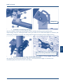
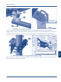
4. Joining of the antenna body and fixing bracket A (B3)
Join the assembled antenna body and fixing bracket A. In order to support the weight of the
antenna, nut (N1) should be fixed as tightly as possible.

PART 1 • English
6
Wall
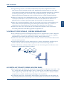
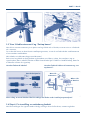
3.3 Step 3: Connecting the antenna and the receiver
Once you have installed the antenna in an open loop space and mounted the way you want it to be
the next step is to connect it all together.
In order to be able to watch your favourite satellite programmes, you need to connect your satellite
antenna to a receiver by a cable.
The cable between the antenna and the satellite receiver should not exceed 30 m as it will decrease
the quality of the signal.
The use of a long or bad quality cable and not isolated jacks can cause a loss of the signal level,
it would be preferable to use an RG6 Coaxial cable (HF 17VATC or 19VATC cable), in order to
minimise a signal loss.
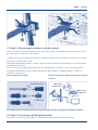
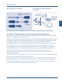
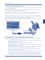
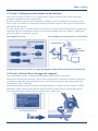
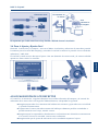
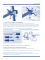
How to prepare the cable? How to connect the cable to the antenna and the
receiver?
Connector cover One side
to Antenna
Cable
Other side
to Receiver
F-connector
It is important that the coaxial cable does not get damaged or kinked during the installation procedure.
3.4 Step 4: Fine tuning and fixing the bracket
Once fine tuning for signal reception is completed, please tighten all bolts and nuts.

PART 1 • English
7
English
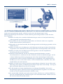
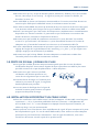
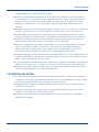
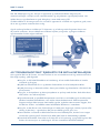
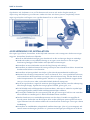
Once all connections are made, turn on the TV and the satellite receiver, select the Antenna Pointing
Menu on your receiver and check the signal level on your TV. Do not forget to choose “LNB: ON”.
Someone will need to stay in front of the TV to tell you when the signal is “good” while you’re
outside adjusting the antenna the best way possible.
The signal level and quality is indicated on the TV screen and will fluctuate and change colour
according to the adjustment & movement of the antenna while you are pointing & finding (azimuth,
elevation angle). The level indicates the power of the signal and the colour indicates the signal
reception quality from the chosen satellite.
4.0 TROUBLESHOOTING CHECK LIST FOR INITIAL INSTALLATION
If the signal is not found, be sure the user manuals for your receiver and antenna have been
followed closely, check the following:
Make sure all cable connections are correct and each connection is seated/tightened properly.
Inspect the inside of each cable connector for dirt or possible connector to case/shield short.
Verify the azimuth, elevation and tilt angles for your location by ZIP code.
Make sure the tilt and elevation pointers are aligned correctly to the scales. Do not use washer
or bolt as reference.
Make sure the tilt adjustment is not changed from the recommended settings for the antenna
location.
Remove existing TV specific components, such as TV splitter, etc; reduce the installation to the
basic connections called out in this guide. Such components may not work with the satellite
signal and they may be in the wall where you can’t see them. When in doubt, run the RG6 cable
directly to you receiver.
Make sure there are no obstructions (trees, buildings, windows, corner or overhang of you roof,
your body or hands) – the signal does not pass leaves, branches, glass, etc.
An RG6 cable with solid copper center conductor is highly recommended because it has much
lower DC voltage drop compared to an RG 6 cable with a copper-coated, steel center conductor.
A standard RG 59 cable causes too much DC drop and signal drop; it cannot be used to pass
the satellite signal. An RG6 coaxial cable must be used.

PART 1 • English
8
Some after-market, off-the-shelf add-on components may not be as advertised. They might
not work or could cause additional DC drops and signal amplitude attenuation. Remove such
components, go back to the basic connections called out in this manual and re-verify.
Make sure the satellite cable is connected to the “SAT IN” jack, not the “ANTENNA IN” jack.
The “ANTENNA IN“ jack at the rear of the receiver is for off-air antenna input or cable TV input.
If all is done correctly but the signal is still not found, change the elevation adjustment of the
antenna slightly (± 2°, then ± 4° from the called-for setting) and repeat the procedure.
Make sure the Access Card of your receiver is fully inserted into the Access Card slot and
oriented correctly.
5.0 LOSS OF SIGNAL/RAIN FADE
The satellite signal may be lost temporarily due to unusual heavy rainfall. An optimal alighted
antenna, along with the shortest possible cable run, minimizes the chances of “rain fade”.
Make sure the antenna is mounted securely to prevent it from being blown out of alignment in a
heavy wind. Heavy snow accumulation on the antenna may reduce the satellite signal strength;
snow should be swept away as soon as possible.
Tree foliage growth into antenna’s line-of-sight to the satellite may result in gradual loss of picture.
6.0 INSTALLATION USING LONG CABLE
For installations where the coaxial cable run from the receiver to the LNB exceeds more
than ~150 feet (~45 m), it can be useful to use the LNB boost function (voltage step-up
0.5 or 1 V), if your receiver is equipped with such a feature. However, long cable runs are
not recommended.
You might also need an additional RF signal amplifier to compensate the signal
amplitude loss. Otherwise, your antenna and receiver may not work properly and be
subject to frequent outages in adverse weather. Contact a professional concerning such
installations.
7.0 TECHNICAL SPECIFICATIONS
Input Satellite Frequency: 10.7 ~ 12.75 GHz
Polarisation: Dual Linear (Horizontal & Vertical)
Antenna Gain: 33.7 dBi at 12.7 GHz

PART 1 • English
9
English
Dimensions (W x H x D): 51.7 x 27.7 x 8.2 cm
LNB: Model SA61: Single LNB integrated
Model SA62: Twin LNB integrated
Model SA64: Quad LNB integrated
LNB Output Frequency: 950 – 1,950 / 1,100 – 2,150 MHz
LNB voltage: Vertical 9 – 14.5 V (typ. 13 V)
Horizontal 15.5 – 24 V (typ. 18 V)
Operating Temperature: -30 ~ +60 °C
Gross weight: 4.5 kg
Net weight: 2.7 kg
Subject to alterations. In consequence of continuous research and development technical specifications, design and appearance of products may change.
ASTRA is a registered trademark of SES ASTRA, Eutelsat and HOT BIRD are registered trademarks of Eutelsat Communications, all other product names are
trademarks or registered trademarks of their respective owners.
© STRONG 2020. All rights reserved.
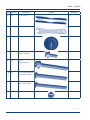
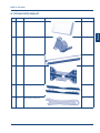
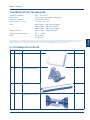
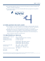
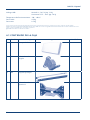
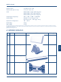
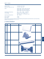
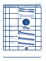
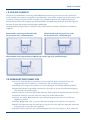
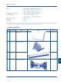
A.1 BOX CONTENT
No Symbol Part name Image Quantity
1 A1 Antenna Body 1
2 B1 Skew Bracket 1
3 B2 Main Support 1
4 B3 Fix Bracket A 1

PART 1 • English
10
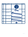
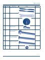
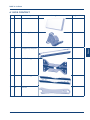
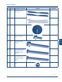
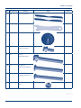
No Symbol Part name Image Quantity
5 B4 Fix Bracket B 2
6 B5 Spanner 1
7 C1 Compass 1
8 S1 Screw
M6x18 SEMS2
3
9 S2 Screw
M6x50 SEMS2
1
10 S3 Round Head Square
Neck Bolt M6x50
3
11 S4 Round Head Square
Neck Bolt M6x75
4
12 N1 Flanged Nut M6 7
22 Nov 2021 13:18

1
Deutsch
PART 2 • Deutsch
BEDIENUNGSANLEITUNG
1.0 WAS IST SLIMSAT? 2
2.0 SICHERHEITSANWEISUNGEN 2
3.0 INSTALLATION 3
3.1 Schritt 1: Wo kann man sie installieren? 3
3.2 Schritt 2: Installation 4
3.3 Schritt 3: Verbinden der antenne mit dem receiver 6
3.4 Schritt 4: Feineinstellung und fixierung der antennenhalterung 7
4.0 STÖRUNGSBEHEBUNGS-PRÜFLISTE FÜR DIE ERSTINSTALLATION 8
5.0 VERLUST DES SIGNALS / REGEN-VERBLASSUNG 9
6.0 INSTALLATION MIT EINEM LANGEN KABEL 9
7.0 SPEZIFIKATION 10
A.1 SCHACHTELINHALT 11
A.2 APPENDIX

2
PART 2 • Deutsch
1.0 WAS IST SLIMSAT?
Die SlimSat ist eine Satellitenantenne vom Typ Hornanordnung mit integriertem LNB, die Signale
von großen Satelliten empfangen und eine normale 65 cm Parabol-Antenne ersetzen kann.
Da sie klein, unauffällig und bedienungsfreundlich ist, kann sie innerhalb von wenigen Minuten
aufgestellt werden und als tragbare Antenne für sämtliche Arten des Satellitenempfangs
verwendet werden.
Die SlimSat kann sowohl für den Empfang frei zugänglicher als auch verschlüsselter Kanäle
verwendet werden. Sie kann auch alle Kanäle mit hochauflösenden Fernsehbildern empfangen.
Um Näheres über Gebrauch und Installation zu erfahren, lesen Sie bitte die nun folgenden
Anweisungen und Installationshinweise sorgfältig durch.
SlimSat SA61 mit integriertem Single LNB SlimSat SA62 mit integriertem Twin LNB
zum Anschluss eines Satelliten Receivers. zum Anschluss an 2 Satelliten Receiver
SlimSat SA64 mit integriertem Quad LNB
für den Anschluss an 4 Receiver
2.0 SICHERHEITSANWEISUNGEN
Vor dem Gebrauch dieses Produkts lesen Sie bitte diese Bedienungsanleitung sorgfältig
durch und befolgen sie Installations-, Montage- und Ausrichtungsanweisungen genau.
Alle Anweisungen sollten befolgt werden, um technische Probleme zu vermeiden.
Jegliches elektrische oder magnetische Feld, das sich in der Nähe der SlimSat befindet,
kann zu schlechtem Empfang führen oder sogar dafür verantwortlich sein, dass das
Gerät vollständig vom Signal getrennt wird.
Bohren Sie den Kunststoffdeckel der Antenne, der diese vor Feuchtigkeit schützt, nicht an.
Gehen Sie vorsichtig mit der Antenne um, da jeglicher Stoß die Geräteelektronik
beschädigen kann.
Öffnen Sie den Deckel nicht, jeglicher Reparatur-Versuch einer nicht entsprechend

3
Deutsch
PART 2 • Deutsch
ausgebildeten Person kann gefährlich sein und die Garantieansprüche erlöschen lassen.
Jegliches Hindernis (Gebäude, Bäume, etc.) blockiert den Empfang des Signals vom
Satelliten an die Antenne.
Malen Sie nichts auf den Antennendeckel oder fügen diesem irgendeine Substanz zu, da
dies den Empfang des Signals vom Satelliten blockiert.
Das Kabel zwischen der Antenne und dem Satellitenempfänger darf nicht länger als 30 m
sein, da dies zur Qualitätsminderung des empfangbaren Signals führt.
Der Gebrauch von nichtisolierten Buchsen führt zum Verlust des Signalpegels.
Vergessen Sie nicht, die Antenne und die Halterung an die Kreuzpolarität anzupassen
(bei schiefem Winkel sehen Sie bitte in Schritt 5 nach).
Ziehen Sie alle Antennenschrauben an, wenn Sie sämtliche Anpassungen vorgenommen
haben.
Dieses Produkt enthält den LNB. Es ist untersagt, einen LNB hinzuzufügen, ihn
auszuwechseln oder zu verändern.
Um Näheres über die oben genannten Punkte oder sonstige weitere Informationen zu
erfahren, wenden Sie sich bitte an Ihren Händler oder den Kundendienst.
WARNUNG !
Nicht korrekte oder unpassend angebrachte Antennen sind leicht durch den Wind zu
beschädigen. Diese Schäden können sehr ernsthafter Natur und sogar lebensgefährlich
sein. Der Eigentümer und Antennen-Installateur übernimmt die volle Verantwortung
dafür, dass die Installation strukturell in Ordnung ist, damit sie sämtliche Lasten tragen
kann (Gewicht, Wind und Eis) und gegen lecke Stellen vorschriftsmäßig abgedichtet ist.
Der Hersteller übernimmt aufgrund der vielen unbekannt variierenden Anwendungen
keine Haftung für Schäden, die durch ein Antennensystem verursacht worden sind.
3.0 INSTALLATION
Mit den folgenden Anweisungen ist es einfach, die SlimSat selbst oder mit Hilfe eines
professionellen Antenneninstallateurs zu installieren.
Kontrollieren Sie bitte vor der Installation den Verpackungsinhalt auf die Vollständigkeit, der im
"Schachtelinhalt" genannten Teile. Für den Fall, dass Teile fehlen, kontaktieren Sie bitte Ihren Händler.
3.1 Schritt 1: Wo kann man sie installieren?
Um ein Signal vom Satelliten zu erhalten, sollte die SlimSat an einer Stelle mit freier Sicht in
Richtung Süden (außerhalb des Hauses oder der Wohnung) in Richtung des Satelliten zum
Äquator hin installiert werden. Hierzu benötigen Sie einen Kompass, um die SlimSat genau auf den
Satelliten hin auszurichten. Anmerkung: Als Bezug nehmen Sie bitte die Tabelle der Azimut-Winkel,
die auf den letzten Seiten dieser Bedienungsanleitung aufgeführt sind.

4
PART 2 • Deutsch
Anmerkung: Zur Sicherstellung einer genauen Ablesung am Kompass, achten Sie bei der
Ablesung bitte darauf, sich nicht in der Nähe von großen Metallobjekten zu befinden,
insbesondere Elektrokabeln und führen Sie außerdem die Ablesung mehrfach durch.
Stellen Sie sicher, dass sich keine Hindernisse, wie etwa Gebäude oder Bäume,
vor der SlimSat befinden, die die Qualität des Signalempfangs beeinträchtigen
(denken Sie daran, dass Bäume wachsen und das Signal blockieren können).
Um Ihre Antenne einfach zu befestigen und zu installieren, können Sie einen
leicht zugänglichen Ort ohne irgendwelche potenziellen Gefahren für die
Installation auswählen.
Denken Sie daran, wie Sie an Ihrem Kabel vorbei ungehindert von der SlimSat zu Ihrem Receiver
gelangen können. Die Antenne sollte sich nicht zu weit entfernt von Ihrem Satelliten Receiver befinden;
ein mehr als 30 Meter langes Kabel kann zu einer Verschlechterung der Empfangsqualität führen.
Signal wird schlecht empfangen Signal wird gut empfangen
3.2 Schritt 2: Installation
Um ihre Antenne wunschgemäß installieren zu können, müssen Sie die Werte für “Azimuth,
Elevation und Skew” (im Anhang der Bedienungsanleitung) beachten, da diese ortsgebunden sind!
Sollte Ihre örtliche Position nicht angegeben sein, dann nehmen Sie bitte die Werte für den
nächstgelegenen Ort zu Hilfe.
In der folgenden Anleitung ist das Beispiel einer Ausrichtung auf Astra 19.2E für die Stadt Brest in
Frankreich angegeben: Der Schiefe Winkel bei -19,7º
der Erhebungswinkel bei 30º
Azimut-Winkel bei 149,6º
Zusammenbau der Teile
1. Einstellung des “schiefen Winkels” (Kreuzpolarisation)
Befestigen Sie den Antennen-Hauptteil (A1) mit der schiefen Halterung (B1) mit den beigepackten
Schrauben (S3) auf den Wert -19,7

5
Deutsch
PART 2 • Deutsch
Überprüfen Sie
die Richtigkeit!
2. Einstellung des Erhebungs- und Azimuth-Winkels
Für die nachhaltige Einstellung der beiden Winkel empfiehlt sich, diese Schrauben nicht allzu fest
anzuziehen, da diese für die Feineinstellung noch beweglich bleiben sollten.
Überprüfen Sie
die Richtigkeit!
3. Wand- oder Mastmontage
Beachten Sie bitte bei der Montage der Fixierungshalterung A (B3) den ausgewählten Platz,
insbesondere welche Charakteristika z.B. die Außenmauer/Fassade/Mast aufweisen. Versichern
Sie sich, dass auch die Ausrichtung der Halterung in Richtung des Satelliten gegeben ist. Um das
Gewicht der Antenne tragen zu können, gewährleisten Sie bitte, dass die entsprechenden Muttern
(N1) so fest wie möglich angezogen sind. Schrauben zur Verankerung in der Wand sind nicht
im Lieferumfang enthalten.

6
PART 2 • Deutsch
Verwenden Sie geeignete Schrauben
zur Verankerung!
Mauer
4. Fertigstellung der Montage
Verbinden Sie nun die fest angebrachte Fixierungshalterung A(B3) mit Hilfe der Hauptstütze (B2)
an den fertig zusammengesetzten Antennen –Hauptteil (A1). Stellen Sie auf jeden Fall sicher, dass
die Muttern (N1) so fest wie möglich angezogen sind.
Mauer
3.3 Schritt 3: Verbinden der Antenne mit dem Receiver
Sobald Sie die Antenne an einem prozessparallelen Ort installiert haben, wie Sie es wollten, ist der
nächste Schritt, alles miteinander zu verbinden.
Um Ihre Lieblings-Satellitenprogramme ansehen zu können, müssen Sie die Satellitenantenne
mittels eines Kabels mit einem Receiver verbinden. Das Kabel zwischen der Antenne und dem
Satelliten Receiver sollte nicht länger als 30 Meter sein, da es den Signalempfang beeinträchtigt. Der
Gebrauch eines zu langen oder eines Kabels schlechter Qualität und nicht isolierter Buchsen kann
zu einem Verlust des Signalpegels führen. Daher wäre es empfehlenswert, ein RG6-Koaxialkabel zu
verwenden, um eine Signalbeeinträchtigung zu minimieren.

7
Deutsch
PART 2 • Deutsch
Wie präpariert man das Kabel? So verbindet man Kabel mit Antenne
und Receiver
Schutzhülse aus Gummi Eine Seite
zur Antenne
Kabel
Andere Seite
zum Digital-
empfänger
F-Stecker
Es ist wichtig, dass das Koaxial-Kabel während der Installation nicht beschädigt oder geknickt wird.
3.4 Schritt 4: Feineinstellung und Fixierung der Antennenhalterung
Wenn die Einstellungen für den optimalen Empfang eingerichtet sind, können die entsprechenden
Schrauben und Muttern festgezogen werden.
Nachdem auch alle Anschlüsse korrekt verbunden worden sind, schalten Sie den Receiver und den Fernseher
ein. Wählen Sie das entsprechende Menü des Receivers zur Antennenausrichtung und überprüfen Sie darin
die Signalpegel. Stellen Sie sicher, dass die Spannungsversorgung für den LNB eingeschalten ist.
Sie werden die Hilfe einer zusätzlichen Person benötigen, die Ihnen vom Fernseher aus Bescheid
gibt, ob das Signal gut ist, während Sie die Antenne für die maximale Signalstärke ausrichten.
Der Signalpegel und die -qualität werden auf dem Bildschirm Ihres Fernsehgeräts angezeigt und
schwanken bzw. ändern ihre Farbe entsprechend der Ausrichtung und Bewegung der Antenne,
während Sie die Einstellungen für Azimut, Erhebung und Schiefer Winkel vornehmen.
Der Pegel zeigt die Signalstärke an und die Farbe steht für die Signalempfangsqualität vom
ausgewählten Satelliten.
Sobald die Feinabstimmung abgeschlossen ist und sich das Signal an seinem Höchstpegel befindet,
können Sie die Ausrichtung der Antenne abschließen.
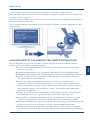
Anmerkung: Zur exakten Ausrichtung der Antenne und zur Erhaltung eines guten Empfang – sogar
bei schlechtem Wetter – verwenden professionelle Antenneninstallateure ein „Signalmessgerät“.
Dieses zeigt den Pegel der vorhandenen Signalstärke an. Nur die Verwendung dieses Messgeräts
garantiert eine wirklich optimale Ausrichtung Ihrer Antenne.

8
PART 2 • Deutsch
4.0 STÖRUNGSBEHEBUNGS-PRÜFLISTE FÜR DIE ERSTINSTALLATION
Sollte kein Signal gefunden werden, stellen Sie sicher, dass die Anweisungen in den
Bedienungsanleitungen des Receivers und der Antenne genau befolgt wurden. Prüfen Sie dazu
bitte Folgendes:
Stellen Sie sicher, dass sämtliche Kabelverbindungen intakt sind und jede Verbindung
ordnungsgemäß sitzt/festgeschraubt ist.
Untersuchen Sie das Innere jedes Kabelsteckers auf Schmutz oder einen möglichen
Stecker-Gehäuseschluss/Schirmschluss.
Überprüfen Sie den Azimutwinkel, den Erhebungswinkel und die Neigungswinkel auf Ihre
örtliche Position.
Stellen Sie sicher, dass die Neigungs- und Erhebungsausrichtung korrekt auf ihre Skalen
ausgerichtet sind. Verwenden Sie als Bezugspunkt keine Unterlegscheibe oder Schraube.
Stellen Sie sicher, dass die Neigungsausrichtung ident ist mit der empfohlenen
Einstellung für den Ort der Antenne.
Entfernen Sie bestehende, für das Fernsehgerät spezifische Bauteile, wie etwa
Fernsehverteiler etc., reduzieren Sie die Installation auf die Grundverbindungen, auf die
in dieser Bedienungsanleitung eingegangen wird. Diese Verbindungen funktionieren
möglicherweise nicht mit diesem Satellitensignal und befinden sich möglicherweise in
der Wand, wo Sie sie nicht sehen können. Falls Sie Zweifel haben, verbinden Sie ein RG
6-Kabel direkt mit Ihrem Receiver.
Stellen Sie sicher, dass es keine Hindernisse gibt (Bäume, Gebäude, Fenster, Ecken oder
Überhänge Ihres Daches, Verdeckung durch Ihren Körper bzw. Ihrer Hände) – das Signal
geht nicht durch Blätter, Äste, Glas etc. hindurch.
Ein RG 6-Kabel mit festem Kupferkernleiter wird dringend empfohlen, da es einen
wesentlich geringeren Gleichstrom-Spannungsabfall aufweist verglichen mit einem RG
6-Kabel mit einem kupferbeschichteten Stahlkern-Leiter.
Ein Standard RG 59-Kabel verursacht einen zu hohen Gleichstrom- und Signal-Abfall; es
kann für eine Weitergabe des Satellitensignals nicht verwendet werden. Hierfür muss ein
RG 6-Koaxial-Kabel verwendet werden.
La pagina si sta caricando...
La pagina si sta caricando...
La pagina si sta caricando...
La pagina si sta caricando...
La pagina si sta caricando...
La pagina si sta caricando...
La pagina si sta caricando...
La pagina si sta caricando...
La pagina si sta caricando...
La pagina si sta caricando...
La pagina si sta caricando...
La pagina si sta caricando...
La pagina si sta caricando...
La pagina si sta caricando...
La pagina si sta caricando...
La pagina si sta caricando...
La pagina si sta caricando...
La pagina si sta caricando...
La pagina si sta caricando...
La pagina si sta caricando...
La pagina si sta caricando...
La pagina si sta caricando...
La pagina si sta caricando...
La pagina si sta caricando...
La pagina si sta caricando...
La pagina si sta caricando...
La pagina si sta caricando...
La pagina si sta caricando...
La pagina si sta caricando...
La pagina si sta caricando...
La pagina si sta caricando...
La pagina si sta caricando...
La pagina si sta caricando...
La pagina si sta caricando...
La pagina si sta caricando...
La pagina si sta caricando...
La pagina si sta caricando...
La pagina si sta caricando...
La pagina si sta caricando...
La pagina si sta caricando...
La pagina si sta caricando...
La pagina si sta caricando...
La pagina si sta caricando...
La pagina si sta caricando...
La pagina si sta caricando...
La pagina si sta caricando...
La pagina si sta caricando...
La pagina si sta caricando...
La pagina si sta caricando...
La pagina si sta caricando...
La pagina si sta caricando...
La pagina si sta caricando...
La pagina si sta caricando...
La pagina si sta caricando...
La pagina si sta caricando...
La pagina si sta caricando...
La pagina si sta caricando...
La pagina si sta caricando...
La pagina si sta caricando...
La pagina si sta caricando...
La pagina si sta caricando...
La pagina si sta caricando...
La pagina si sta caricando...
La pagina si sta caricando...
La pagina si sta caricando...
La pagina si sta caricando...
La pagina si sta caricando...
La pagina si sta caricando...
La pagina si sta caricando...
La pagina si sta caricando...
La pagina si sta caricando...
La pagina si sta caricando...
La pagina si sta caricando...
La pagina si sta caricando...
La pagina si sta caricando...
-
 1
1
-
 2
2
-
 3
3
-
 4
4
-
 5
5
-
 6
6
-
 7
7
-
 8
8
-
 9
9
-
 10
10
-
 11
11
-
 12
12
-
 13
13
-
 14
14
-
 15
15
-
 16
16
-
 17
17
-
 18
18
-
 19
19
-
 20
20
-
 21
21
-
 22
22
-
 23
23
-
 24
24
-
 25
25
-
 26
26
-
 27
27
-
 28
28
-
 29
29
-
 30
30
-
 31
31
-
 32
32
-
 33
33
-
 34
34
-
 35
35
-
 36
36
-
 37
37
-
 38
38
-
 39
39
-
 40
40
-
 41
41
-
 42
42
-
 43
43
-
 44
44
-
 45
45
-
 46
46
-
 47
47
-
 48
48
-
 49
49
-
 50
50
-
 51
51
-
 52
52
-
 53
53
-
 54
54
-
 55
55
-
 56
56
-
 57
57
-
 58
58
-
 59
59
-
 60
60
-
 61
61
-
 62
62
-
 63
63
-
 64
64
-
 65
65
-
 66
66
-
 67
67
-
 68
68
-
 69
69
-
 70
70
-
 71
71
-
 72
72
-
 73
73
-
 74
74
-
 75
75
-
 76
76
-
 77
77
-
 78
78
-
 79
79
-
 80
80
-
 81
81
-
 82
82
-
 83
83
-
 84
84
-
 85
85
-
 86
86
-
 87
87
-
 88
88
-
 89
89
-
 90
90
-
 91
91
-
 92
92
-
 93
93
-
 94
94
-
 95
95


in altre lingue
- français: Strong SA61 Manuel utilisateur
- español: Strong SA61 Manual de usuario
- Deutsch: Strong SA61 Benutzerhandbuch
- dansk: Strong SA61 Brugermanual
- svenska: Strong SA61 Användarmanual