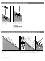
Endura Ultimate Multi-Point Astragal Istruzioni per l'uso
- Tipo
- Istruzioni per l'uso

1
Multi-Point Astragal
Prehanger Installation Instructions
Rev. Date: 6.20.2023
©Endura Products, Inc.
Innovation protected under patents and patents pending
in U.S. and Canada. See www.EnduraPatents.com.
#211159-MPPREHINST
• Endura Router Template (or equivalent)
• Router with 5/8" diameter guide collar
• 1/2" Router Bit
• Recommended Bit:
• 1/2" Diameter Straight Flute
• 1/2" Diameter Shank
• 2-1/2" Cut Length
(Amana Bit 45427 or equivalent)
• Phillips Screwdriver
• 1" Spade Drill Bit
• 1/8" Diameter Drill Bit
• Power Driver with #2 Phillips Bit
• Tape Measure
• Pencil
• Clamps (2)
Tools Required:
NOTES:
1. Pre-drill pilot holes where indicated.
3. Overtightening of screws may cause improper operation.
4. Minimum handle height for use with this astragal is 33-1/4".
Keeper Pack Includes:
(4) #8 x 1" Mounting Screws
(2) Keeper Assemblies
Screw Pack Includes:
(12) #8 x 1-1/2" Painted Screws
(4) 1" Mounting Screws
Please note that all screws may
not be used.
(4) #8 x 3" Painted Screws
Kit Includes:
• Full Astragal
• Full Piece of Trim Strip
• Screw Pack
• Keeper Pack
• Field Pack
8817 West Market Street
Colfax, NC 27235 | 800.334.2006
www.enduraproducts.com

2
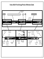
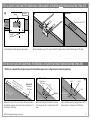
Endura Multi-Point Astragal Product Reference Guide:
Trim Strip with
Sealing Fin
Lower Bolt
Head
Lower
Bolt Lock
Pawl Lower Bolt
Sleeve
Lower Trim
Cap
Simple
Solution∏
Corner Pad
Upper Bolt
Head
Upper Trim
Cap
Upper Bolt
Lock Pawl
Flip Lever
Assembly
Deadbolt
Actuator
Actuator
Adjuster
Screw
Strike Plate
Strike
Retainer
Upper Bolt
Lock Pawl
Housing
Lower Bolt
Lock Pawl
Housing
Upper Bolt
Sleeve

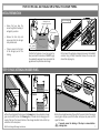
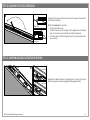
Multi-Point Astragal Prehanger Instructions 3
a. Determine and mark the centerline of both lock pawls on the astragal.
b. Measure distance between the two centerlines (X). Measurement should end with 3/8".
c. Record measurement for use with Endura template.
STEP 1: MEASURE DISTANCE BETWEEN LOCK PAWL CENTERLINES
Lock Pawl
Centerline
Lock Pawl
Centerline
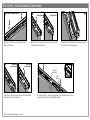
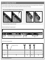
I. LOWER ROUT:
a. Depending on the panel thickness (either 1-3/4" thick or 1-11/16"
thick), identify the corresponding side of the template.
b. Position the router template so that the centerline of the template
is 8-5/16" from the bottom of the door panel.
c. Securely clamp router template in place.
d. Using a 5/8" diameter collar and 1/2" bit, rout the pocket for the
keeper assembly.
II. UPPER ROUT:
a. Determine the position of the upper rout by adding 8-5/16" to the
measurement of distance between the lock pawls' centerline (X) on
the astragal from Step 1 (X + 8-5/16"). Distance will always end in
11/16" and will vary in 1" increments.
Example: If the centerline distance is 60-3/8", the template
position would be 65-11/16" (60-3/8" + 8-5/16" = 68-11/16")
b. Measure from the centerline of the template in the lower rout
position and mark the new position as the centerline of the template
in the upper rout position.
c. Securely clamp router template in place.
d. Using a 5/8" diameter collar and 1/2" bit, rout the pocket for the
keeper assembly.
STEP 2A: ROUT ACTIVE DOOR PANEL FOR KEEPER ASSEMBLY (WITH ENDURA ROUTING TEMPLATE)
X
ACTIVE PANEL
STRIKE SIDE
CLAMP
ROUTER TEMPLATE
(template is symmetrical)
CLAMP
8-5/16"
CLAMP
CLAMP
Active Door
Panel
Each side of the template
corresponds to either a
1-3/4" door or 1-11/16"
door panel and is labeled
accordingly.
PART A: ROUTING INSTRUCTIONS FOR KEEPER ASSEMBLIES AND DEADBOLT ACTUATOR
Top of Door Panel
X
Template
Centerline
Lower Rout
Centerline
I
II
Bottom of
Door Panel

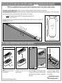
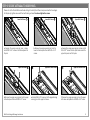
Multi-Point Astragal Prehanger Instructions 4
2.531 +.000
-.025
1.031 +.000
-.025
0.440+.000
-.025
DEEP
R 0.250
ROUT DETAIL
Center on panel thickness
X = Distance between the
lock pawls' centerline
7-1/16"
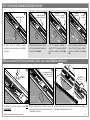
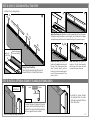
STEP 2B: ROUT ACTIVE DOOR PANEL FOR KEEPER ASSEMBLY (WITHOUT ENDURA ROUTING TEMPLATE)
NOTE: Keeper pivot arm rests in
an open position.
STEP 3: INSTALL KEEPER ASSEMBLY INTO ACTIVE DOOR PANEL
NOTE: If you completed Step 2A, please proceed to Step 3. The steps below are only for routing without an Endura template.
Example: If the centerline distance is 60-3/8", the pocket position would be 67-7/16"
(60-3/8" + 7-1/16" = 67-7/16")
c. Once the pocket positions are located and clearly marked, rout the door panel using the measurements included in the
Rout Detail guide on the right.
a. Determine Lower Rout Pocket Position: The bottom of the lower rout pocket should be 7-1/16" from the bottom of the door panel.
b. Determine Upper Rout Pocket Position: The bottom of the upper rout pocket should be X (the distance between the lock pawls' centerline) + 7-1/16" from the bottom
of the door panel (X+7-1/16"). The distance will end in 7/16" and will vary in 1" increments:
KEEPER ASSEMBLY
a. Remove the spacer from the
keeper assembly.
b. Install the spacer into each pocket as shown.
The open side of the keeper must face the same
side as the barrel of the hinges on the opposite
door panel.
Spacer
Keeper
a
Barrel of Hinges
Open Side of Keeper
b
Overtightening of screws may
cause improper operation.
c. Secure the keeper assembly
installing one of the #8 x 1" screws
into each keeper.
!

Multi-Point Astragal Prehanger Instructions 5
STEP 3 (CONT.): INSTALL KEEPER ASSEMBLY INTO ACTIVE DOOR PANEL
!Overtightening of screws may
cause improper operation.
d. Reinstall the spacer into the
keeper assembly.
e. Install the second #8 x 1" screw
through the spacer and the keeper
into the door panel.
d e
Distance between the top
of the Active Door Panel to
Deadbolt Centerline
Top of Active
Door Panel
a. Mark the center of the rout location at the centerline of the deadbolt
crossbore.
b. Position the deadbolt centerline to be lined up with the lower small mark on the template.
Make sure to use the side of the template that matches the door panel thickness.
STEP 4A: ROUT INACTIVE DOOR PANEL FOR DEADBOLT ACTUATOR (WITH ENDURA ROUTING TEMPLATE)
a b
Deadbolt
Centerline
Deadbolt
Centerline

Multi-Point Astragal Prehanger Instructions 6
Door
Panel
Top of Door
Panel
c. The template should be aligned as shown above.
STEP 4A (CONT.): ROUT INACTIVE DOOR PANEL FOR DEADBOLT ACTUATOR (WITH ENDURA ROUTING TEMPLATE)
c
Top of Door
Panel
d. Rout the pocket using a 1/2" router bit with 5/8" diameter collar, rout slot in the door panel 7/16" deep.
Depth of Pocket = 7/16"
Finished Rout
d
Deadbolt
Centerline
Top View
Lower Small
Mark
Top of Door
Panel
a. Mark the center of the rout location at the centerline of
the deadbolt crossbore. Once marked, drill a hole that is 1" in
diameter and 7/16" deep.
Drill Hole #1:
1" Diameter x
7/16" Deep
1-1/4"
Center to Center
b. Drill a second hole 1-1/4" above the rst hole.
This hole will also be 1" in diameter and 7/16"
deep.
c. Drill a third hole directly in between holes 1 and 2.
This hole will be 1" in diameter and 7/16" deep.
Hole 2
Hole 1
Hole 3
STEP 4B: ROUT INACTIVE DOOR PANEL FOR DEADBOLT ACTUATOR (WITHOUT ENDURA ROUTING TEMPLATE)
Hole #1
Drill Hole #2:
1" Diameter x
7/16" Deep
NOTE: If you completed Step 4A, please proceed to Step 5. Below steps are for routing without an Endura template only.
Drill Hole #3:
1" Diameter x
7/16" Deep
a b c
Distance between the top
of the Active Door Panel to
Deadbolt Centerline

Multi-Point Astragal Prehanger Instructions 7
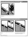
PART B: INSTALL ASTRAGAL ONTO INACTIVE DOOR PANEL
• Ensure that you have the
correct length and handing of
astragal for your door.
• Remove the trim strip and
screw pack from the astragal
body and set aside.
• If tape is present on the back
of the astragal, peel off the
backing.
Back of Astragal
On the back of the astragal, a shipping clip secures the deadbolt
actuator. Using a Phillips Screwdriver, remove the screws and
discard the shipping clip.
Conrm the thickness of your door panel. For
door panels with thicknesses of 1-11/16", apply
the available B-seal gasket to accommodate the
gap between the panel face and astragal.
Top View of
Inactive Door
Lip should t
snug against
the door panel
B-Seal Gasket
INITIAL PREPARATION
If present, peel tape
backing to secure
astragal to passive door
b
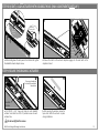
STEP 5: PLACE ASTRAGAL ON DOOR PANEL
a. Place the astragal onto the door panel. For Inswing doors, the wide side of astragal
goes on outside of the door. For Outswing doors, the wide side of astragal goes on
inside of the door. The top and bottom of the astragal should be ush with the top
and bottom of the door panel.
Top View of
Inactive Door
Top View of
Inactive Door
Interior
Exterior
Interior
Exterior
INSWING
OUTSWING
a
b. Press the astragal down along the length of the panel. A total of ve orange
securing pins will pop up around the lower and upper lock pawls, and the
upper bolt sleeve.
Top and bottom of
the astragal should
be ush with the
door panel.
!If present, ensure the backing of the tape is removed before
pressing down.

Multi-Point Astragal Prehanger Instructions 8
STEP 6: SECURE ASTRAGAL TO DOOR PANEL
a. Keeping the orange securing pins in place,
install #8 x 1-1/2" screws in the holes adjacent to
the pins.
a
Please refer to the Product Reference Guide on Page 2 to identify the different components within the astragal.
For Step 6, only tighten screws until ush with mating surfaces. Do not overtighten the screws.
Lower Bolt Shown
b. Remove the orange securing pins from the
lower bolt and replace them with #8 x 1-1/2"
screws.
c b
c. Keeping the orange securing pins in place, install
#8 x 1-1/2" screws into the open holes around the
upper lock pawl, next to the pins.
Lower Bolt Shown Upper Bolt Shown
Bottom of Panel
Bottom of Panel
Top of Panel
d
d. Remove the orange securing pins from the upper
bolt and replace them with #8 x 1-1/2" screws.
e
e. Install a #8 x 1-1/2" screw next to the popped orange
securing pin on the upper bolt sleeve.
Upper Bolt Sleeve Shown
f. Remove the orange securing pin from the upper
bolt sleeve and replace it with a #8 x 1-1/2" screw.
Upper Bolt Sleeve Shown
f
Upper Bolt Shown
Top of Panel

Multi-Point Astragal Prehanger Instructions 9
STEP 6 (CONT.): SECURE ASTRAGAL TO DOOR PANEL
h
g. Secure the ip lever assembly with two
#8 x 1-1/2" screws.
g
h. Remove the lower bolt sleeve retainer screw and
slide out the lower bolt sleeve.
i
i. Install #8 x 1" screws into the holes directly above
the U-notch on the astragal body.
Lower Bolt
Sleeve Shown
Lower Bolt
Sleeve Shown
Flip Lever Assembly Shown
Bottom of Panel
k. Install two #8 x 1" screws into the holes in the astragal body on either
side of the strike retainer and deadbolt actuator.
j. Return the bolt sleeve onto the lower bolt and reinstall
the screw securing the bolt sleeve.
k
j Lower Bolt
Sleeve Shown
Lower Bolt
Sleeve Shown
Deadbolt
Actuator
Strike
Retainer
Top of Panel
x2

Multi-Point Astragal Prehanger Instructions 10
STEP 7: DETERMINE DEADBOLT ACTUATOR POSITION
a. Check where the deadbolt actuator
scoreline is positioned relative to the deadbolt
centerline.
b. If the actuator scoreline is in line
with the panel deadbolt crossbore
centerline, skip to Step 9.
c. If the actuator scoreline is
within 1/4" of the panel deadbolt
crossbore centerline, follow Step
8A.
Deadbolt Scoreline
Deadbolt
Crossbore
Centerline
Actuator
Scoreline
<1/4"
Deadbolt
Centerline Actuator
Scoreline
>1/4"
Deadbolt
Centerline
Deadbolt Centerline
and Actuator Scoreline
ab c d
Hold Down
the Lower Bolt
Lock Pawl
Bottom of Panel
Actuator
Adjuster
Screw
a. Loosen the actuator adjuster screw TWO
TURNS ONLY!
b. Move the actuator up or down to line up the
score line on the actuator body with the center of
the deadbolt crossbore.
STEP 8A: ALIGN ACTUATOR WITH DEADBOLT HOLE (ONLY ADJUSTMENTS UNDER 1/4")
x2 ONLY
Centerline of the
Inactive Panel
Deadbolt Bore
Actuator
Adjuster
Screw
Move deadbolt actuator
up or down to line up
the scoreline.
c. While holding down the lock pawl on the bottom bolt, tighten
the deadbolt actuator adjuster screw.
a
!
bc
d. If the actuator scoreline is more
than 1/4" from the panel deadbolt
crossbore centerline, follow Step
8B.

Multi-Point Astragal Prehanger Instructions 11
STEP 8A (CONT.): ALIGN ACTUATOR WITH DEADBOLT HOLE (ONLY ADJUSTMENTS UNDER 1/4")
d. Ensure the teeth on the actuator adjuster engage into the rack teeth on the
adjustment insert.
Adjustment
Insert
Actuator
Adjuster
d
Teeth
Engagement
b. Line up the scoreline on the actuator body with the center of the
inactive panel deadbolt crossbore and rotate the actuator into the
astragal body, starting at narrow edge of astragal.
b
a. Rotate the actuator out of the astragal body toward the narrow edge of the
astragal.
a
STEP 8B: ALIGN ACTUATOR WITH DEADBOLT HOLE (ONLY ADJUSTMENTS OVER 1/4")

Multi-Point Astragal Prehanger Instructions 12
c. While holding down the lock pawl on the bottom bolt, tighten
the deadbolt actuator adjuster screw.
Hold Down
the Lower Bolt
Lock Pawl
Bottom of Panel
Actuator
Adjuster
Screw
d. Ensure the teeth on the actuator adjuster engage into the rack teeth on the
adjustment insert.
Adjustment
Insert
Actuator
Adjuster
c d
Teeth
Engagement
Actuator
Adjuster
Screw
STEP 8B (CONT.): ALIGN ACTUATOR WITH DEADBOLT HOLE (ONLY ADJUSTMENTS OVER 1/4")
STEP 9: SECURE THE DEADBOLT ACTUATOR
a. Drill Ø1/8" x 1-1/2" deep pilot holes at each deadbolt
actuator hole. Install four #8 x 3" painted screws into each
actuator hole.
Drive screw heads just
ush with the surface of
the actuator.
a
b. After securing the actuator, remove the
tape which holds the actuator in place
during installation.
b
!Do not overtighten the screws.
Deadbolt
Actuator

Multi-Point Astragal Prehanger Instructions 13
STEP 10: CONFIRM FLIP LEVER OPERATION
a. Engage the ip lever assembly and ensure both the upper and lower bolts
move in and out smoothly.
b. If the bolts do not operate smoothly:
• Check for bolt obstructions.
• Check that the screws in the astragal are not overtightened in the astragal
body. The top of the screw should be ush with the astragal body.
• If the lever operation is difcult, slightly loosen the screws securing the ip
lever assembly.
Upper Bolt
Lower Bolt
a
STEP 11: CONFIRM DEADBOLT ACTUATOR OPERATION
a. Operate the deadbolt actuator by pressing down on it. Ensure the top and
bottom lock pawls move between engaged and disengaged positions.
Press a
Lower Bolt
Lock Pawl
Upper Bolt
Lock Pawl

Multi-Point Astragal Prehanger Instructions 14
STEP 12: SIZE AND INSTALL TRIM STRIP
Trim strip is included as a single, full-length piece and must be sized to t appropriately between the astragal components. For each segment, measure, cut and install the
trim strip, ensuring the sealing n side of the trim stip is installed on the side closest to the weatherstrip on the astragal.
a. Measure the length between the astragal components.
X1X2X3X5
X4
a
Ensure the upper and lower bolts are in the retracted position. Secure the strike plate into the proper location by aligning it with the lever
crossbore hole and tighten the screws into the retainer.
Before measuring the length between astragal components, check the following:
b. Cut the trim strip into appropriate sizes.
X1X2X3X5
X4
b
Sealing Fin on Trim Strip

Multi-Point Astragal Prehanger Instructions 15
STEP 12 (CONT.): SIZE AND INSTALL TRIM STRIP
c. Install trim into astragal body.
X1
X2
X3X4
X5
Upper Trim Strips: Align X1with the top of the upper bolt and top of the upper
lock pawl housing. Press down to secure. Align X2 with the bottom of the upper
lock pawl housing and the top of the deadbolt actuator. Press down to secure.
Lower Trim Strip: Align X5 with the
bottom of the ip lever assembly
and the top of the lower lock pawl
housing. Press down to secure.
Middle Trim Strips: Align X3 with the
bottom of the deadbolt actuator and
the top of the strike retainer. Press
down to secure. Align X4 with the
bottom of the strike retainer and the
top of the ip lever assembly. Press
down to secure.
Sealing Fin on Trim Strip:
The sealing n should be aligned closest to
the weatherstrip for the best performance.
Sealing Fin
on Trim Strip
Weatherstrip (gray
to show contrast)
X1X2
X3 & X4X5
c
STEP 13: INSTALL OPTIONAL SECURITY FLANGE (OUTSWING ONLY)
Active Door
Panel
a. Position the security ange on the active
door panel with the wide ange facing the
outside of the house. Peel the tape backing
and secure against the active panel.
b. Install the screws through
the predrilled holes to secure
the ange snug against the face
of the active door.
Active Door
Panel
Top View
Inside Outside
OUTSWING
DOORS ONLY
b a
-
 1
1
-
 2
2
-
 3
3
-
 4
4
-
 5
5
-
 6
6
-
 7
7
-
 8
8
-
 9
9
-
 10
10
-
 11
11
-
 12
12
-
 13
13
-
 14
14
-
 15
15


Endura Ultimate Multi-Point Astragal Istruzioni per l'uso
- Tipo
- Istruzioni per l'uso
in altre lingue
Documenti correlati
Altri documenti
-
Arregui KEEPER-E Manuale utente
-
 Steris Keeper Device Clip Istruzioni per l'uso
-
Edgewater Networks 240IS Manuale del proprietario
-
Axial AXI90081T1 Manuale del proprietario
-
-
 Hangar 9 HAN4720CR Manuale del proprietario
-
Whirlpool UMV1160CB0 Guida d'installazione
-
Bolens 31AE9P3J565 Manuale del proprietario
-
IKEA IMH172DS0 Guida d'installazione
-
Regal 42 Fly-Grande Coupe Manuale del proprietario

