
127x69
156
82
49
59
67
134
4
34.5
Fig. 1
7<:/
Fig. 2
Fig. 3
1 2 3 4 5 6 7
9 10 118
L
LN
DEF. T.
DI
AMB. T.
NTC
PROBES
SERIAL
CONV
-10T50
230V~
PROG.
KEY
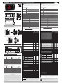
Fig. 4
WARNING: separate as much as possible the probe and digital input signal
cables from the cables carrying inductive loads and power cables to avoid
possible electromagnetic disturbance. Never run power cables (including the
electrical panel wiring) and signal cables in the same conduits.
NO POWER
& SIGNAL
CABLES
TOGETHER
READ CAREFULLY IN THE TEXT!
Disposal of the product: the appliance (or the product) must be disposed of separa-
tely in accordance with the local waste disposal legislation in force.
IMPORTANT WARNINGS
The CAREL product is a state-of-the-art product, whose operation is specifi ed in the technical
documentation supplied with the product or can be downloaded, even prior to purchase,
from the website www.carel.com. - The client (builder, developer or installer of the fi nal equip-
ment) assumes every responsibility and risk relating to the phase of confi guration the product
in order to reach the expected results in relation to the specifi c fi nal installation and/or equi-
pment. The lack of such phase of study, which is requested/indicated in the user manual, can
cause the fi nal product to malfunction of which CAREL can not be held responsible. The fi nal
client must use the product only in the manner described in the documentation related to
the product itself. The liability of CAREL in relation to its own product is regulated by CAREL’s
general contract conditions edited on the website www.carel.com and/or by specifi c agree-
ments with clients.
PJ easy XL - ENERGY SAVING con micro porta/ ENERGY SAVING with door switch
+050004180 - rel. 1.2 - 25.07.13
Dimensioni (mm) / Dimensions (mm)
Montaggio a pannello / Panel mounting
Frontale (con 2 viti ø 4 mm) /
Front (with 2 screws ø 4 mm)
Da dietro (con 2 staff e posteriori) / Rear (with 2 quick-fi t side brackets)
Descrizione
PJ easy XL rappresenta una gamma di regolatori elettronici a microprocessore con visua-
lizzazione a LED realizzati per la gestione del risparmio energetico delle unità frigorifere,
tramite la rilevazione del micro porta. Lo stato della porta determina il cambiamento del
set point e l’accensione/spegnimento della luce.
Caratteristiche tecniche
alimentazione 230 Vac +10 /-15% 50/60 Hz; 115 Vac +10 /-15% 50/60 Hz
12 Vac +10/-15% 50/60 Hz classe 2; 12 Vdc +10/-20% classe 2
potenza nomi-
nale
3,5 VA
ingressi sonda NTC 2 ingressi. 1 ingresso digitale
uscite relè relè 2 Hp UL60730: 12 A Res. 12 FLA 60 LRA - 240 Vac C300,
EN60730-1: 10(10)A 250 Vac
relè 8 A UL: 8 A Res. 2 FLA 12 LRA - 240 Vac C300,
EN60730-1: 8(4)A NO, 6(4)A NC, 2(2)A CO - 250 Vac
tipo di sonda NTC Std CAREL 10 KΩa 25 °C
connessioni Morsetti estraibili per blocchetti a vite o con contatto a crimpare (sez. cavo
fi no a 2,5 mm2). Corrente nominale massima per morsetto 12 A.
montaggio per terminale: mediante viti dal frontale o con staff e posteriori
visualizzazione display LED 2 cifre con segno (-99…99) e punto decimale; sei LED di stato
condizioni di funzionamento -10T50 °C - umidità <90% U.R. non condensante
condizioni di immagazzinamento -20T70 °C - umidità <90% U.R. non condensante
intervallo di rilevazione -50T90 °C (-58T194 °F) - risoluzione 0,1 °C/°F
grado di protezione frontale montaggio a quadro con guarnizione: IP65 tipo 1
contenitore terminale plastico, 156x82x59 mm
classifi cazione secondo la prote-
zione contro le scosse elettriche
classe II per incorporamento adeguato
inquinamento ambientale normale
PTI dei materiali di isolamento 250 V
periodo delle sollecitazioni elet-
triche delle parti isolanti
lungo
categoria di resistenza al calore
e al fuoco
categoria D
immunità contro le sovratensioni categoria 1
tipo di azione e disconnessione contatti relè 1C
n.ro di cicli di manovra delle ope-
razioni automatiche relè
EN60730-1: 100.000 operazioni
classe e struttura del software classe A
pulizia dello strumento utilizzare esclusivamente detergenti neutri ed acqua.
lunghezza max. cavi seriale: 1 km
sonde: 30 m
relè: 10 m
AVVERTENZA: non passare cavi di potenza a meno di 3 cm dalla parte inferiore del dispositivo
o dalle sonde; per le connessioni usare solo cavi di rame.
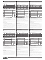
Tabella parametri
Parametro Min. Max. Def. U.M.
PS Password 0 99 22
/ PARAMETRI SONDA
/2 Stabilità misura sonde 1 15 4
/4 Selezione sonda visualizzata 1 3 1
/5 Selezione u.d.m. sonde °C / °F 0 1 0
/6 Disabilita punto decimale 0 1 0
/8 Off set di visualizzazione -99.0 +99.0 0.0 °C/°F
/9 Temperatura minima visualizzata -40.0 /A -3.5 °C/°F
/A Temperatura massima visualizzata /9 /b 3.0 °C/°F
/b Soglia di segnalazione temperatura visualizzata /A 199.0 13.0 °C/°F
/E Stabilità temperatura visualizzata 1 50 10 Min.
-C1 Off set sonda 1 -50.0 50.0 0.0 °C/°F
-C2 Off set sonda 2 -50.0 50.0 0.0 °C/°F
r PARAMETRI REGOLAZIONE
St Set point r1 r2 0.0 °C/°F
rd Diff erenziale 0,0 19.0 3.0 °C/°F
r1 Set point minimo ammesso -50.0 r2 0.0 °C/°F
r2 Set point massimo ammesso r1 99.0 5.0 °C/°F
r4 Aumento del Set-Point durante il Risparmio Energetico 1.0 50.0 3.0 °C/°F
r5 Diff erenziale durante il Risparmio Energetico 0.0 19.0 3.0 °C/°F
r6 Tempo commutazione automatica da Normale a
Risparmio Energetico
r6 = 0, il Risparmio Energetico è attivato solo con il
tasto Energy Saving
0903hr
r7 Tempo commutazione automatica da Risparmio Ener-
getico a Normale
r7 = 0, funzionamento normal è attivato con il tasto
Energy Saving o aprendo la porta
1906hr
r8 Per attivazione manuale da tastiera del Risparmio
Energetico:
nei casi di termostato installato internamente al
cabinet,
rappresenta il tempo di attesa di chiusura della porta.
0 90 10 sec
r9 Questo timer è inizializzato quando il compressore è
OFF. Se la temperatura è superiore a St+Pt e r9 non è
scaduto, la modalità Energy Saving non è abilitata
0244hr
Pt Diff erenziale per il pull-down 0.0 30.0 15.0 °C/°F
C PARAMETRI COMPRESSORE
c0 Rit. partenza comp. dopo accensione 0 200 0 min
c1 Tempo minimo tra accensioni successive 0 100 3 min
c2 Tempo minimo di Off del compressore 0 100 5 min
c3 Tempo minimo di On del compressore 0 100 0 min
c4 Duty setting 0 100 0 min
d PARAMETRI SBRINAMENTO
d0 Tipo di sbrinamento
INIZIO FINE
0 A tempo (dI) A tempo (dP)
1 A tempo (dI) In temperatura (dt) o a tem-
po (dP)
2 In temperatura (dA) In temperatura (dt) o a tem-
po (dP)
3 In temperatura (dA)
o a tempo (dI)
A tempo (dP) con controllo in
temperature (dt)
033
-d0 Defi nisce se sbrinamento a gas caldo o meno.
0 = sbrinamento normale ( compressore OFF )
1 = sbrinamento gas caldo ( compressore ON )
010
dI Intervallo tra i defrost 0 199 3 hr
-dI Modalità di conteggio dell’intervallo dI:
0 = dI viene conteggiato sempre;
1 = dI viene conteggiato solo quando il compressore è ON
010
dt Temperatura Evaporatore di fi ne defrost -50.0 99.0 15.0 °C/°F
dP Durata massima defrost 1 199 20 min
d4 Abilitazione defrost allo start up 0 1 0
d5 Ritardo defrost da start up 0 199 0 min
d6 Blocco display durante il defrost 0 1 0
dd Tempo di gocciolamento dopo il defrost 0 15 0 min
d8 Esclusione allarmi dopo il defrost 0 15 15 hr
d9 Priorità defrost su protezioni compressore 0 1 0
d/ Valore sonda defrost 0 0 0 °C/°F
dA Temperatura sonda Evaporatore per inizio defrost -50.0 99.0 -20.0 °C/°F
db Temperatura sonda Regolazione per abiliazione defrost -50.0 99.0 15.0 °C/°F
dE Allarme Perdita Refrigerante: tempo di monitoraggio
della tendenza a scendere della temperatura di rego-
lazione
A9 199 199 min
A PARAMETRI DI ALLARME
A0 Diff erenziale allarme -20.0 20.0 -2.0 °C/°F
AL Soglia/Scostamento di allarme di bassa temperatura -50.0 150.0 -20.0 °C/°F
AH Soglia/Scostamento di allarme di alta temperatura -50.0 150.0 60.0 °C/°F
Ad Ritardo allarme bassa e alta temperatura 0 199 0 min
A9 Ritardo allarme porta aperta 0 10 2 min
H ALTRE IMPOSTAZIONI
H0 Indirizzo seriale 0 207 1
H2 Abilitazione tastiera 0 1 1
H4 Disabilitazione buzzer
0= buzzer abilitato; 1= buzzer disabilitato
010
H5 Rileva parametri modifi cati 1 199 0
Collegamenti elettrici / Electrical connections
Tabella allarmi
Codice
allarme
buzzer e relè allarme LED Descrizione allarme Parametri
coinvolti
E0 attivi ON errore sonda 1= regolazione -
E1 non attivi ON errore sonda 2= defrost [d0 = 1/2/3]
E3 attivi ON Allarme perdita di refrigerante dE
dr attivi ON allarme porta aperta -
LO attivi ON allarme bassa temperatura [AL] [Ad]
HI attivi ON allarme alta temperatura [AH] [Ad]
EE non attivi ON errore parametri macchina -
EF non attivi ON errore parametri funzionamento -
dF non attivi OFF defrost in esecuzione [d6=0]
serial conv. IROPZ485S0
prog. key IROPZKEY* or PSOPZKEY*
Table of alarms
Alarm
code
buzzer and alarm
relay
LED Description Parameters
involved
E0 active ON probe 1 error= control -
E1 inactive ON probe 2 error= defrost [d0 = 1/2/3]
E3 active ON refrigerant system failure alarm dE
dr active ON open door alarm -
LO active ON low temperature alarm [AL] [Ad]
HI active ON high temperature alarm [AH] [Ad]
EE inactive ON unit parameter error -
EF inactive ON operating parameter error -
dF inactive OFF defrost running [d6=0]
Description
PJ easy XL represent a range of electronic microprocessor controllers with LED display de-
veloped for the management of the energy saving display cabinets and showcases, by the
detection of door-switch. The status of the door determines the change of set point and
ON/OFF of the light.
Technical speci cations
power supply 230 Vac +10 /-15% 50/60 Hz; 115 Vac +10 /-15% 50/60 Hz
12 Vac +10/-15% 50/60 Hz class 2; 12 Vdc +10/-20% class 2;
rated power 3,5 VA
inputs 2 NTC probes. 1 digital input.
relay outputs 2 Hp relay UL60730: 12 A Res. 12 FLA 60 LRA - 240 Vac C300,
EN60730-1: 10(10)A 250 Vac
8 A relay UL: 8 A Res. 2 FLA 12 LRA - 240 Vac C300,
EN60730-1: 8(4)A NO, 6(4)A NC, 2(2)A CO - 250 Vac
type of probe Std CAREL NTC 10 KΩ at 25 °C
connections Plug-in terminals for screw blocks or with crimped contact (cable cross-sect.
up to 2.5 mm
2
). Rated maximum current per terminal 12 A.
assembly terminal: using screws from the front panel or with rear brackets
display 2 digit LED display with sign (-99 to 99) and decimal point; six status LEDs
operating conditions -10T50 °C - humidity <90% rH non-condensing
storage conditions -20T70 °C - humidity <90% rH non-condensing
range of measurement -50T90 °C (-58T194 °F) - resolution 0.1 °C/°F
front panel index of protection panel installation with IP65 type 1 gasket
case plastic terminal, 156x82x59 mm
classifi cation according to protection
against electric shock
Class II when suitably integrated
environmental pollution normal
PTI of the insulating material 250 V
period of stress across the insulating
parts
long
category of resistance to heat and fi re category D
immunity against voltage surges category 1
type of action and disconnection 1C relay contacts
no. of relay automatic operating
cycles (*)
EN60730-1: 100,000 operations
software class and structure Class A
cleaning the instrument Only use neutral detergents and water.
cable max. lenght serial: 1 km
probes: 30 m
relay: 10 m
WARNING: do not run the power cable less than 3 cm from the bottom part of the device or
from the probes; for the connections only use copper wires.
NO POWER
& SIGNAL
CABLES
TOGETHER
READ CAREFULLY IN THE TEXT!
Table of parameters
Parameter Min. Max. Def. U.M.
PS Password 0 99 22
/ PROBE PARAMETERS
/2 Measurement stability 1 15 4
/4 Select probe/input displayed 1 3 1
/5 Select °C / °F 0 1 0
/6 Disable decimal point 0 1 0
/8 Visualization off set -99.0 +99.0 0.0 °C/°F
/9 Minimum shown temperature -40.0 /A -3.5 °C/°F
/A Maximum shown temperature /9 /b 3.0 °C/°F
/b Signaling temperature threshold /A 199.0 13.0 °C/°F
/E Shown temperature stability 1 50 10 Min.
-C1 Probe 1 off set -50.0 50.0 0.0 °C/°F
-C2 Probe 2 off set -50.0 50.0 0.0 °C/°F
r CONTROL PARAMETERS
St Set point r1 r2 0.0 °C/°F
rd Standard diff erential 0,0 19.0 3.0 °C/°F
r1 Minimum set point allowed to the user -50.0 r2 0.0 °C/°F
r2 Maximum set point allowed to the user r1 99.0 5.0 °C/°F
r4 Increase the Set-Point during Energy Saving 1.0 50.0 3.0 °C/°F
r5 Diff erential during Energy Saving 0.0 19.0 3.0 °C/°F
r6 Automatic time from Normal to Energy Saving
If r6 = 0, Energy saving is available only with Energy
Saving button.
0903hr
r7 Automatic time from Energy Saving to Normal
If r7 = 0, normal mode is available only with Energy
Saving button or opening the door
0906hr
r8 To enter in Saving mode by keyboard:
time to allow the door closure for “Open Front”
cabinet.
0 90 10 sec
r9 This timer is initialized when the compressor is OFF. If
the temperature is above St+Pt and r9 is not expired,
Energy Saving mode is not enabled.
0244hr
Pt Pull-down diff erential 0.0 30.0 15.0 °C/°F
C COMPRESSOR PARAMETERS
c0 Comp. start delay after start-up 0 200 0 min
c1 Min. time between successive comp. starts 0 100 3 min
c2 Min. compressor OFF time 0 100 5 min
c3 Min. compressor ON time 0 100 0 min
c4 Duty setting 0 100 0 min
d DEFROST PARAMETERS
d0 Type of defrost
START STOP
0 By time (dI) By time (dP)
1 By time (dI) By temperature (dt) or by
time (dP)
2 By temperature (dA) By temperature (dt) or by
time (dP)
3 By temperature (dA)
or by time (dI)
By time (dP) with tempera-
ture control (dt)
033
-d0 Defi nes whether or not defrost is hot gas.
0 = normal defrost (compressor OFF)
1 = hot gas defrost (compressor ON)
010
dI Interval between two defrosts 0 199 3 hr
-dI Mode for counting the interval dI:
0 = dI is always counted;
1 = dI is only counted when the compressor is ON
010
dt End defrost temperature -50.0 99.0 15.0 °C/°F
dP Max. or eff ective defrost duration 1 199 20 min
d4 Defrost when the instrument is switched on 0 1 0
d5 Defrost delay on start-up 0 199 0 min
d6 Disable temperature display during defrost 0 1 0
dd Dripping time after defrost 0 15 0 min
d8 Alarm bypass time after defrost 0 15 15 hr
d9 Defrost priority over compressors protectors 0 1 0
d/ Display defrost probe temp. 0 0 0 °C/°F
dA Start up defrost evaporator temperature -50.0 99.0 -20.0 °C/°F
db Regulation temperature enable defrost -50.0 99.0 15.0 °C/°F
dE Refrigerant system failure alarm: monitoring time to
decrease the regulation temperature
A9 199 199 min
A ALARM PARAMETERS
A0 Alarm temperature diff erential -20.0 20.0 -2.0 °C/°F
AL Low temperature alarm threshold/deviation -50.0 150.0 -20.0 °C/°F
AH High temperature alarm threshold/deviation -50.0 150.0 60.0 °C/°F
Ad Low and high temperature alarm delay 0 199 0 min
A9 Open door alarm delay 0 10 2 min
H OTHER SETTINGS
H0 Serial address 0 207 1
H2 Enable keypad 0 1 1
H4 Disable buzzer
0= buzzer enabled; 1= buzzer disabled
010
H5 Modifi ed parameters detect 1 199 0
Smaltimento del prodotto: L’apparecchiatura (o il prodotto) deve essere oggetto di
raccolta separata in conformità alle vigenti normative locali in materia di smaltimento

CAREL INDUSTRIES HQs
Via dell’Industria, 11 - 35020 Brugine - Padova (Italy)
Tel. (+39) 0499716611 – Fax (+39) 0499716600 – http://www.carel.com – e-mail: [email protected]
CAREL reserves the right to modify the features of its products without prior notice.
Visualizzazione e funzioni
Durante il normale funzionamento il controllo visualizza a display il valore della sonda
impostata con il parametro /4 (=1 sonda ambiente di default, =2 seconda sonda). Inol-
tre sul display appaiono i LED che indicano l’attivazione delle funzioni del controllo (vedi
Tab. 1), mentre i 4 tasti permettono di attivare/disattivare alcune funzioni (vedi Tab. 2).
LED e funzioni associate
Icona Funzione Normale funzionamento Start up
ON OFF Blink
Energy Saving attiva disattiva - -
Compressore acceso spento richiesto ON
Allarme tutti nessun allarme - ON
Luce accesa spenta - ON
Defrost acceso spento richiesto ON
Tab. 1
Tabella attivazione funzioni tramite i tasti
Tasto Normale funzionamento Start up
Pressione del singolo tasto
- per almeno 3 s.: attiva/disattiva modalità “ENERGY
SAVING”
- premendo il tasto, prima che venga attivata/disattivata
la modalità “ENERGY SAVING”, il display mostrerà la sigla
“-E” (energy saving) o “-n” (normale) come anteprima.
-
- per almeno 3 s.: attiva defrost
-
- più di 5 s: accesso menù impostazione parametri
(inserire password ‘22’)
- Tacita allarme acustico (buzzer)
Premuti
insieme
attivano
procedura
RESET
parametri.
per 1 s
RESET
banco EZY
corrente
- per almeno 0.5 s.: attiva/disattiva l’uscita LUCE
per 1 s
visualizza
cod. vers.
fi rmware
Tab. 2
Accesso e modi ca parametri
1. premere SET per 5 s (sul display comparirà “PS”);
2. per accedere al menù parametri digitare la password “22” con UP/DOWN;
3. navigare all’interno del menù parametri con UP/DOWN;
4. per visualizzare/modifi care i valori del parametro visualizzato premere SET, quindi UP/
DOWN ed infi ne SET per confermare la modifi ca (si ritorna così al menù dei parametri).
Per salvare defi nitivamente tutti i valori modifi cati ed uscire dal menù parametri premere
SET per 3 s.
Per uscire dal menù senza salvare i valori modifi cati (uscita per time out) non premere alcun
tasto per almeno 60 s.
Normative di sicurezza
conforme alle Normative europee in materia. Precauzioni d’installazione:
• i cavi di collegamento devono garantire l’isolamento fi no a 90 °C;
• per le versioni 12 Vac utilizzare trasformatori Classe II. Per il rispetto delle normative EN 61000-
4-4, EN 61000-4-5, EN 61000-4-11, EN 61000-4-6, EN 60730-1, il trasformatore deve essere uno
dei modelli indicati (vedi Listino Prezzi CAREL). Per le versioni 12 Vac/dc, non essendo possibile
garantire il doppio isolamento tra i connettori di alimentazione e le uscite relè, si raccomanda
di utilizzare carichi alimentati solamente in bassissima tensione di sicurezza (fi no a 42 V nomi-
nali di valore effi cace);
• prevedere almeno 10 mm di distanza tra il contenitore e parti conduttive vicine;
• collegamenti degli ingressi digitali e analogici inferiori a 30 m di distanza; adottare le adegua-
te misure di separazione dei cavi per il rispetto delle normative suddette.
Bloccare bene i cavi di connessione delle uscite per evitare contatti con parti in bassissima ten-
sione di sicurezza.
+050004180 - rel. 1.2 - 25.07.13
A chage et fonctions
Pendant le fonctionnement normal le contrôle affi che sur l’ écran la valeur de la sonde
réglée au paramètre/4 (=1sonde air ambiant par défaut, =2 deuxième sonde). De plus
sur l’ écran apparaissent les LED qui indiquent l’ activation des fonctions de contrôleo
(voir Tab. 1), alors que les 4 touches permettent d’ activer/désactiver certaines fon-
ctions (voir Tab. 2).
LED et fonctions associées
Icone Fonction Fonctionnement normale Start up
ON OFF Blink
Energy Saving accès éteint - -
Compresseur accès éteint requis ON
Alarme tous aucune alarme - ON
Lumière accès éteint - ON
Defrost accès éteint requis ON
Tab. 1
Tableau activation fonctions à l’aide des touches
Touche Fonctionnement normale start up
Simple pression de la touche
- plus de 3 s.: active/désactive mode “ENERGY
SAVING”
- appuyant sur la touche avant que active/dé-
sactive mode “ENERGY SAVING”, l’écran affi che
le symbole “-E” energy saving) ou “-n” (normal)
comme un aperçu
-
- plus de 3 s: active/désactive sortie defrost -
- plus de 5 s: accès au menu règlages paramètres
(entrer mot de passe ‘22’)
- Eteint l’ alarme accoustique (buzzer)
Appuyées
ensemble
activent
procédure
REINITIALISA-
TION param.
pour 1 s RESET
banc EZY
courant
- plus de 0.5 s.: active/désactive sortie “LUMIÈRE” pendant 1 s
affi che cod.
vers. fi rmware
Tab. 2
Accès et modi cation paramètres
1. Appuyer sur SET pendant 5 s (sur l’ écran apparaitra “PS”);
2. pour accéder au menu paramètres entrer le mot de passe “22” en utilisant UP/DOWN;
3. naviguer à l’ intérieur du menu paramètresen utilisant UP/DOWN;
4. pour affi cher/modifi er les valeurs du paramètre affi ché appuyer sur SET, ensuite sur UP/
DOWN et enfi n sur SET pour cconfi rmer la modifi cation (on retourne ainsi au menu des
paramètres).
Pour sauver défi nitivamente toutes les valeurs modifi ées et sortir du menu paramètres ap-
puyer sur SET pendant 3 s.
Pour sortir du menu sans suaver les valeurs modifi ées (sortie timeout) n’ appuyer sur aucun
bouton pendant au moins 60s.
Normes de sécurité
conformes aux Normes européennes pertinentes. Precautions d’ usage:
• les câbles de connexion doivent garantir l’ isolation jusqu’ à 90 °C;
• pour les versions12 utiliser transformateurs ClasseII. Pour la conformité à la norme EN 61000-4-
4, EN 61000-4-5, EN 61000-4-11, EN 61000-4-6, EN 60730-1, le transformateur doit être l’un des
modèles (voir catalogue CAREL). Pour les versions 12Vac/dc, une double isolation ne peut être
garantie entre l’alimentation et les relais de sortie, utiliser uniquement avec des charges basse
tension (jusqu’à 42 V nominal effi cace);
• laisser au moins 10 mm de distance entre le boitier et les parties conductibles voisines;
• Connexions des entrées digitales analogiques inférieures à une distance de 30m; adopter les me-
sures de séparation appropriées des câbles pour le respect des normes de sûreté.
Bloquer avec soin les câbles de connexion des sorties pour éviter les contacts avec les éléments
sous Très Basse tension de sécurité.
Visualizaciones y funciones
Durante el funcionam. normal, el control muestra en el display el valor de la sonda
ajustada con el parám. /4 (=1 sonda ambiente predeterminada, =2 segunda sonda).
Además, en el display aparecen los LED que indican la activación de las funciones
del control (ver Tab. 1), mientras que las 4 teclas permiten activar desactivar algunas
funciones (ver Tab. 2).
LED y funciones asociadas
Icono Función Funcionamiento normal Arranque
ON OFF Parpadeo
Energy Saving encendido apagado - -
Compresor encendido apagado demanda ON
Alarma todas ninguna alarma - ON
Luz encendido apagado - ON
Deshielo encendido apagado demanda ON
Tab. 1
Tabla de activación de funciones por medio de las teclas
Tecla Funcionamiento normal Start up
Presión de la tecla sola
- más de 3 s.: activa/desactiva la mod. de “ENERGY
SAVING”
- pulsando la tecla, antes de que està activa/de-
sactiva la mod. de “ENERGY SAVING”, la pantalla
mostrará el símbolo “-E” (energía de ahorro) o “-n”
(normal), como una vista previa
-
- más de 3 s: activa salida defrost -
- más de 5 s: acceso al menú de ajuste de paráme-
tros (insertar contraseña ‘22’)
- apaga alarma acústica (zumbador)
Pulsados
juntos
activan el pro-
cedimiento
RESET de los
parámetros
por 1 s RESET
banco EZY
corriente
- más de 0.5 s: activa/desactiva salida LUZ durante 1 s
muestra cód.
vers. fi rmware
Tab. 2
Acceso y modi cación de parámetros
1. Pulsar SET durante 5 s (en el display aparecerá “PS”);
2. Para acceder al menú de los parámetros tecle la contraseña “22” con ARRIBA/ABAJO;
3. Navegar al interior del menú de parámetros con ARRIBA/ABAJO;
4. Para visualizar/modifi car los valores del parámetro visualizado pulsar SET, y luego ARRIBA/
ABAJO y fi nalmente SET para confi rmar la modifi cación (así se vuelve al menú de los
parámetros).
Para guardar defi nitivamente todos los valores modifi cados y salir del menú de los parám.
pulsar SET durante 3 s.
Para salir del menú sin guardar los valores modifi cados (salida por agotamiento de tiempo)
no pulsar ninguna tecla durante al menos 60 s.
Normativas de seguridad
Conforme a las Normativas europeas de la materia. Precauciones de instalación:
• Los cables de conexión deben garantizar el aislamiento hasta a 90 °C;
• Para las versiones de 12 Vca utilizar transformadores de Classe II. Para respetar las normativas
EN 61000-4-4, EN 61000-4-5, EN 61000-4-11, EN 61000-4-6, EN 60730-1, el transformador debe
ser de uno de los modelos indicados (ver Lista de Precios de CAREL). Para las versiones 12
vac/dc, no siendo posible garantizar el aislamiento doble, entre el conector de alimentación
y las salidas relés, se aconseja utilizar cargas alimentadas solamente con muy baja tensión de
seguridad (hasta 42V nominales de valor efi caz);
• Prever al menos 10 mm de distancia entre el contenedor y las partes conductoras próximas;
• Conexiones de las entradas digitales y analógicas inferiores a 30 m de distancia; adoptar las
medidas adecuadas de separación de cables para respetar la normativa de inmunidad.
Bloquear bien los cables de conexión de las salidas para evitar contactos con las partes en bají-
sima tensión de seguridad.
Anzeige und Funktionen
Bei Normalbetrieb zeigt das Display den Wert des im Parameter /4 eingestellten
Fühlers an (=1 Default-Raumfühler, =2 zweiter Fühler). Die Display-LEDs zeigen außer-
dem den Aktivierungszustand der Funktionen an (siehe Tab. 1), während über die 4
Tasten einige Funktionen aktiviert/deaktiviert werden können (siehe Tab. 2).
LEDs und Funktionen
Pikt. Funktion Normalbetrieb Start
EIN AUS Blinkt
Energy Saving Eingeschaltet Ausgeschaltet - -
Verdichter Eingeschaltet Ausgeschaltet Angefordert EIN
Alarm Alle Kein Alarm - EIN
Light Eingeschaltet Ausgeschaltet - EIN
Abtauung Eingeschaltet Ausgeschaltet Angefordert EIN
Tab. 1
Tabelle der Funktionsaktivierung über die Tasten
Button Normal operation start up
Pressing the button alone
- Für länger als 3 Sek.: aktiviert/nicht aktiviert “ENER-
GY SAVING” Modus
- Drücken der Tasten, vor der Modus-“ENERGY SA-
VING” aktiviert/ nicht aktiviert, das display anzeigt
“-E” (energy saving) oder “-n” (Normal) wie Vorshau.
-
- Für länger als 3 Sek.: Anzeige Abtauung -
- Für länger als 3 Sek.: Zugriff auf das Menü der
Parameter- konfi guration (Passwort ‘22’ eingeben)
- Stellt akustischen Alarm (Summer) ab
Zusammen
gedrückt
wird das
Parameter-
RESET
aktiviert
für 1 Sek., die
active EZY Kabine
RESET
- Für länger als 0.5 Sek.: Anzeige/Einstellung LIGHT-
Ausgang
Für 1 Sek. wird
der Code der
Firmware-Version
eingeblendet
Tab. 2
Zugri und Änderung der Parameter
1. SET für 5 Sekunden drücken (auf dem Display erscheint “PS”).
2. Für den Zugriff auf das Menü der Parameter das Passwort “22” mit UP/DOWN eingeben.
3. Das Parametermenü kann mit UP/DOWN abgelaufen werden.
4. Zur Anzeige/Änderung der Parameterwerte SET, dann UP/DOWN und schließlich SET zur
Bestätigung der Änderung drücken (es erfolgt die Rückkehr zum Parametermenü).
Zur endgültigen Speicherung aller geänderten Werte und zum Verlassen des Parameter-
menüs SET für 3 Sek. drücken.
Zum Verlassen des Menüs ohne Speicherung der geänderten Werte (Verlassen wegen Time-
out) für mindestens 60 Sek. keine Taste drücken.
Sicherheitsvorschriften
Übereinstimmung mit den einschlägigen europäischen Vorschriften. Vorsichtsmaßnahmen bei
der Installation:
• Die Anschlusskabel müssen bis zu 90 °C Isolierung garantieren.
• Für die 12 Vac-Versionen Trafos der Klasse II verwenden. Zur Einhaltung der Vorschriften EN
61000-4-4, EN 61000-4-5, EN 61000-4-11, EN 61000-4-6, EN 60730-1 muss der Trafo einem der
angegebenen Modelle entsprechen (siehe CAREL-Preisliste). Da für die 12-Vac/dc-Versionen
nicht die doppelte Isolierung zwischen den Versorgungssteckern und den Relaisausgängen
garantiert werden kann, sollten nur mit SELV versorgte Lasten verwendet werden (bis 42 V
eff ektive Nennspannung).
• Mindestens 10 mm Abstand zwischen dem Gehäuse und den leitenden Teilen vorsehen.
• Die Anschlüsse der digitalen und analogen Eingänge müssen weniger als 30 m Abstand auf-
weisen; die Kabel sind zur Einhaltung der obgenannten Vorschriften angemessen zu trennen.
Die Anschlusskabel der Ausgänge gut befestigen, um Kontakte mit Niedrigstspannungsteilen
zu vermeiden.
Display and functions
During normal operation, the controller displays the value of the probe set using pa-
rameter /4 (=1 ambient probe, default, =2 second probe). In addition, the display has
LEDs that indicate the activation of the control functions (see Table 1), while the 4
buttons can be used to activate/deactivate some of the functions (see Table 2).
LEDs and associated functions
Icon Function Normal operation Start up
ON OFF Blink
Energy
Saving
on off --
Compressor on off request ON
Alarm all no alarm - ON
Light on off -ON
Defrost on off request ON
Tab. 1
Table of functions activated by the buttons
Button Normal operation start up
Pressing the button alone
- more than 3 s.: activate/deactivate “ENERGY SAVING”
mode
- pushing the keypad, before the “ENERGY SAVING”
mode will toggle, the display will show “-E” (Energy
Saving) or “-n” (normal) as preview.
-
- more than 3 s.: activate defrost -
- more than 5 s: access parameter setting menu (enter
psw ‘22’)
- mute acustic alarm (buzzer)
Pressed
together start
parameter
RESET pro-
cedur
for 1 s RESET
current EZY
set
- more than 0.5 s.: the light status will be toggled for 1 s display
fi rmware
vers. code
Tab. 2
Access and setting parameters
1. press SET for 5 s (the display will show “PS”);
2. to access the parameter menu, enter the password “22” using UP/DOWN;
3. scroll inside the parameter menu using UP/DOWN;
4. to display/set the values of the parameter displayed, press SET, then UP/DOWN and fi nally
SET to confi rm the changes (returning to the parameter menu).
To save all the new values and exit the parameter menu, press SET for 3 s;
To exit the menu without saving the changed values (exit by timeout) do not press any button
for at least 60 s.
Safety standards
Compliant with the relevant European standards. Installation precautions:
• the connection cables must guarantee insulation up to 90 °C;
• for 12 Vac versions use Class II transformers. To ensure compliance with the immunity
standards (surge), the transformer must be one of the models specifi ed (see the CAREL price
list). For the 12 Vac/dc versions, as double insulation cannot be guaranteed between the
power supply and the relay outputs, only use safety low voltage loads (up to 42 V eff ective
rated value);
• ensure a space of at least 10 mm between the case and the nearby conductive parts;
• digital and analogue input connections less than 30 m away; adopt suitable measures for
separating the cables so as to ensure compliance with the immunity standards;
Secure the connection cables of the outputs so as to avoid contact with very low voltage parts.
Visualização e funções
Durante o normal funcionamento, o controle indica no visor o valor da sonda progra-
mada com o parâmetro/4 (=1 sonda ambiente por defeito,=2 segunda sonda). No visor
aparecem também os LEDs que indicam a activação das funções de controle (ver Tab.
1), enquanto que as 4 teclas permitem activar/desactivar algumas funções (ver Tab. 2).
LEDs e funções associadas
Ìcone Função Normal funcionamento Start up
ON OFF Blink
Energy Saving ligado desligado - -
Compressor ligado desligado solicitado ON
Alarme todos nenhum alarme - ON
Luz ligado desligado - ON
Defrost ligado desligado solicitado ON
Tab. 1
Tabela de ativação das funções através de botões
Tecla Normal funcionamento Start up
Pressão de uma única tecla
- mais de 3 s.: activa/desactiva modalidad “ENERGY SA-
VING”
- premiendo la tecla, antes de està activa/desactiva la
modalidad “ENERGY SAVING”, display mostrará o símbo-
lo “-E” (energy saving) o “-n” (normale) come anteprima.
-
- mais de 3 s: activa/desactiva saida Defrost -
- mais de 5 s: acesso ao menu de programação de
parâmetros (inserir password ‘22’)
- silencia o alarme acústico (buzzer)
Premidas
ultânea-
mente
activam/o
procedimen-
to RESET
parâmetros
por 1 seg.
RESET
bancadas
EZY activadas
- mais de 0.5 s: activa/desactiva saida LUZ durante 1 s
visualiza cód.
vers. fi rmware
Tab. 2
Acesso e modi cação dos parâmetros
1. prema SET durante 5 s (no visor aparecerá “PS”);
2. para aceder ao menu de parâmetros do tipo F e C digite a password “22” com UP/DOWN;
3. navegue no menu de parâmetros com UP/DOWN;
4. para visualizar/modifi car os valores do parâmetro visualizado prema SET, e depois UP/DOWN
e de novo SET para confi rmar a modifi cação (regressa então ao menu dos parâmetros).
Para guardar defi nitivamente todos os valores modifi cados e sair do menu de parâmetros
prema SET durante 3 s.
Para sair do menu sem guardar os valores modifi cados (saída por “time out”) não prema
nenhuma tecla durante pelo menos 60s.
Normas de segurança
Conformes às Normativas europeias na matéria. Precauções de instalação:
• os cabos de ligação devem garantir o isolamento até aos 90ºC;
• para as versões 12 Vac utilize transformadores Classe ll. Para respeitar as normativas de imu-
nidade (Surge), o transformador deve ser escolhido entre os modelos indicados (ver Lista de
Preços CAREL). Para as versões 12 Vac/dc, como a dupla isolação não pode ser garantida entre
a fonte de tensão e os relés, somente utilize cargas de baixa voltagem (até 42V médios efe-
tivos);
• preveja pelo menos 10mm de distância entre o contentor e as partes condutoras vizinhas;
• ligações das entradas digitais e analógicas inferiores a 30m de distância; adopte as medidas
de separação adequadas para os cabos de modo a respeitar as normativas de imunidade.
Bloqueie bem os cabos de conexão das saídas para evitar contactos com partes em Baixissima
Tensão de segurança.
-
 1
1
-
 2
2


in altre lingue
- English: Carel PJ easy XL User manual
- français: Carel PJ easy XL Manuel utilisateur
- português: Carel PJ easy XL Manual do usuário
Documenti correlati
-
Carel Datalogger Manuale utente
-
-
Carel SmartCella 3PH WP00B24A10 Quick Manual
-
Carel UltraCella Assembly And Installation
-
-
-
-
-
-
Altri documenti
-
Kegco ICXCK-1B-2 Manuale utente
-
Giacomini K465P Istruzioni per l'uso
-
Danfoss 080G3296 Guida d'installazione
-
-
-
-