Carel MCH200*03 Assembly Instructions
- Categoria
- Termostati
- Tipo
- Assembly Instructions
Questo manuale è adatto anche per

MCH200*03 - µC
2
SE: Dispositivo elettronico per controllo di chiller a 2/4 compressori (mono e bicircuito) / Electronic controller for chillers with 2/4 compressors (one and two circuits)
Vi ringraziamo della scelta fatta, sicuri che sarete soddisfatti del vostro acquisto.
Introduzione
μC
2
SE è un controllo elettronico per la gestione completa di chiller, pompe di calore, motocondensanti e unità aria/aria fino ad un circuito
con 2 compressori ermetici. Con la scheda di espansione (cod. MCH200002*) si possono gestire fino a 2 circuiti e 4 compressori ermetici.
Caratteristiche dei connettori
I connettori possono essere acquistati separatamente
presso CAREL (MCH2CON0**) o dal costruttore
Molex‚:
Codice dei contatti e sezione dei cavi di collegamento ai connettori a 12 e
14 vie (utilizzare per la crimpatura l’apposito attrezzo Molex‚
69008-0724):
Codice Molex‚ del Connettore Numero di vie Codice Molex‚ del contatto Sezione dei cavi ammessa
39-01-2120 12 39-00-0077 AWG16 (1.25 mm
2
)
39-01-2140 14 39-00-0038 AWG18-24 (0.90-0.35 mm
2
)
39-00-0046 AWG22-28 (0.22-0.06 mm
2
)
Numero massimo di inserzioni/disinserzioni dei connettori: 25 cicli. Sono inoltre disponibili i kit precablati MCHSMLC***.
Istruzioni per il montaggio
Lunghezza massima cavi di collegamento sonde NTC/Raziometrica: 10 m
Lunghezza massima cavi di collegamento ingressi digitali: 10 m
Lunghezza massima cavi di collegamento uscite di potenza: 5 m
Lunghezza massima cavi di collegamento uscita pilotaggio fan: 5 m
Lunghezza massima cavi di alimentazione: 3 m
Lunghezza massima cavi di collegamento tLAN: 10 m
L’utilizzo di alcuni input/output dipende dalla configurazione dei parametri.
Esempio di configurazione
Connettore Connessione Significato
14 vie G-G0 Alimentazione μC
2
SE
B1-GND Sonda aria ambiente (unità aria-aria), sonda acqua ingresso evaporatore (refrigeratori d’ac-
qua), aria in mandata
B2-GND Sonda acqua uscita evaporatore, controllo resistenza antigelo
B3-GND Sonda controllo condensazione, resistenza di appoggio
ID1-GND Ingresso multifunzione configurato da parametro P8 (vedi manuale d’uso)
ID2-GND Ingresso multifunzione configurato da parametro P9 (vedi manuale d’uso)
ID3-GND Pressostato di alta pressione
ID4-GND Pressostato di bassa pressione
ID5-GND Ingresso multifunzione configurato da parametro P34 (vedi manuale d’uso)
Y-GND Uscita PWM per modulo azionamento ventilatore di condensazione
12 vie No1- C1/2 Compressore 1
No2- C1/2 Uscita multifunzione configurato da parametro P25 (Se H11= 12)
No3- C3/4 Uscita multifunzione configurato da parametro P26 (Se H11= 12)
No4- C3/4 Uscita multifunzione configurato da parametro P27 (Se H11= 12)
No5- C5 Uscita multifunzione configurato da parametro P28 (Se H11= 12)
estraibile 2 vie
(tLAN)
TxRx - GND Permette la connessione della scheda di espansione per il secondo circuito (cod.
MCH00002*) e del modulo driver valvola EVD000040*
estraibile 3 vie
(b4/idb4)
B4 - GND (V+
alimentazione
sonda raziometrica)
Ingresso digitale IDB4 (parametro P13)/ Sonda raziometrica pressione di condensazione /
Sonda temperatura esterna.
Configurabile da parametro “/4”
Opzione chiave di programmazione parametri
A controllo spento, inserire la chiave PSOPZKEY00 nel connettore KEY/SPV. Effettuare la connessione e disconnessione dell’opzione
seriale e chiave di programmazione con connettore 12 vie (relè) disinserito.
Nota: Il ponticello di configurazione va inserito nella posizione A (fogl. istruz. MCH200485*).
Opzione supervisore
Collegare al connettore KEY/SPV l’opzione seriale (cod. MCH200485*).
Avvertenze
• IncasodisingolotrasformatoredialimentazionetraμC
2
SE ed accessori è necessario connettere tutti i terminali G0 (dei vari controlli
o delle varie schede allo stesso morsetto del secondario e tutti i terminali G all’altro morsetto del secondario) al fine di evitare il
danneggiamento dello strumento;
• Perimpiegoinambientedomesticoènecessariol’utilizzodicavoschermato(unconduttore+schermo)perleconnessionidella
tLAN (EN 55014-1);
• EvitarecortocircuititraV+eGNDpernondanneggiarelostrumento;
• Tenereseparatiicavidipotenza(usciterelè)daicavirelativiallesonde,ingressidigitaliedelleseriali;
• Utilizzarel’alimentazionedatrasformatorededicataesclusivamenteaicontrollielettronici;
Protezione contro le scosse elettriche e avvertenze per la manutenzione
Togliere l’alimentazione prima di intervenire sulla scheda in fase di montaggio, manutenzione e sostituzione.
Il sistema composto dalla scheda controllo (MCH200*03*) e dalle altre schede opzionali (MCH200002*, MCH200485*, MCHRTF****,
CONVONOFF*, CONV0/10A*, EVD000040*) costituisce un dispositivo di comando da incorporare in apparecchiature di tipo classe I o
classe II. La classe relativa alla protezione contro le scosse elettriche dipende dalla modalità con cui viene eseguita l’integrazione del dispo-
sitivo di comando nella macchina realizzata dal costruttore.
La protezione contro i cortocircuiti, per cablaggi difettosi, deve essere garantita dal costruttore dell’apparecchiatura in cui il dispositivo di
comando viene integrato.
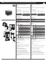
Esempio di configurazione / Configuration example
Fig. 1
G0 B1 B2 B3 ID5 ID3 ID1
G
GND
GND
Y
GND
ID4 ID2
No1
C1/2 C1/2 C3/4
x C5
N02 No3 No4
C3/4
x No5
cond. probe
outlet probe
inlet probe
low press.
multi funct.
multi funct.
high press.
multi funct.
Line
L
N
To program key
To serial link
RS485
option
EV driver ESP
tLAN
Tx/Rx GND
GND
B4
V+
P
pressure
probe
temperature
probe
digital
imput
Key/SPV
Line
LN
EV Driver
EV Driver
Expansion
board
EV driver
Thank you for your choice. We trust you will be satisfied with your purchase.
Introduction
The μC
2
is an electronic controller for the complete management of chillers, heat pumps, condensing units and air/air units with one cir-
cuit and 2 hermetic compressors. The expansion board (code MCH200002*) allows the management of up to 2 circuits and 4 hermetic
compressors.
Characteristics of the connectors
The connectors can be purchased separately from
CAREL (MCH2CON0**) or from the manufacturer,
Molex:
Contact code and cross-section of the connection cables to the 12- and
14-pin connectors (for crimping, use the special Molex tool‚
69008-0724):
Molex connector code number of pins Molex contact code Cross-section of the cables allowed
39-01-2120 12 39-00-0077 AWG16 (1.25 mm
2
)
39-01-2140 14 39-00-0038 AWG18-24 (0.90-0.35 mm
2
)
39-00-0046 AWG22-28 (0.22-0.06 mm
2
)
Maximum number of connections/disconnections: 25 cycles. The pre-wired kits MCHSMLC*** are also available.
Assembly instructions
Maximum connection cable length, NTC/Ratiometric probes: 10 m
Maximum connection cable length, digital inputs: 10 m
Maximum connection cable length, power outputs: 5 m
Maximum connection cable length, fan control output: 5 m
Maximum length, power cables: 3 m
Maximum length of tLAN connection cables: 10 m
The use of some inputs/outputs depends on the configuration of the parameters.
Configuration example
Connector Connection Meaning
14 pin G-G0 μC2 power supply
B1-GND Ambient air probe (air-air units), evaporator water inlet probe (water chillers), outlet air
probe
B2-GND Evaporator water outlet probe, anti-freeze heater control
B3-GND Condensing pressure control probe, auxiliary heater
ID1-GND Multifunction input configured by parameter P8 (see user manual)
ID2-GND Multifunction input configured by parameter P9 (see user manual)
ID3-GND High pressure switch
ID4-GND Low pressure switch
ID5-GND Multifunction input configured by parameter P34 (see user manual)
Y-GND PWM output for condenser fan module operation
12 pin No1- C1/2 Compressor 1
No2- C1/2 Multifunction output configured by parameter P25 (if H11 = 12)
No3- C3/4 Multifunction output configured by parameter P26 (if H11 = 12)
No4- C3/4 Multifunction output configured by parameter P27 (if H11 = 12)
No5- C5 Multifunction output configured by parameter P28 (if H11 = 12)
removable 2 pin
(tLAN)
TxRx - GND It allows connecting μC2 with the expansion board for the management of the second
circuit (code MCH00002*) and valve driver module EVD000040*
removable 3 pin
(B4/IDB4)
B4 - GND (V+ power
supply ratiometric
probe)
Digital input IDB4 (parameter P13)/ Ratiometric condensing pressure probe / Outside
temperature probe
Can be configured by parameter “/4”
Parameter programming key option
With the controller OFF, insert the key PSOPZKEY00 in the connector KEY/SPV. Connect and disconnect the serial and programming key
options with the 12-pin connector (relay) removed.
Note: the configuration jumper must be inserted in position A (technical leaflet MCH200485*)
Supervisor option
Connect the serial option (code MCH200485*) to the connector KEY/SPV.
Warnings
• IfusingasinglepowertransformerfortheμC
2
SE and the accessories, connect all the G0 terminals on the various controllers or boards
to the same terminal on the secondary, and all the G terminals to the other terminal on the secondary, to avoid damaging the
instrument;
• Foruseinresidentialenvironments,ashieldedcable(conductor+shield)isrequiredforthetLANconnections(EN55014-1);
• Avoidshort-circuitsbetweenV+andGNDsoastonotdamagetheinstrument:
• Separatethepowercables(relayoutputs)fromtheprobe,digitalinputandserialcables;
• Usethepowertransformerexclusivelydedicatedtotheelectroniccontrollers.
Protection against electric shock and warnings for maintenance
Disconnect the power supply before working on the board during the assembly, maintenance and replacement operations.
The system made up of the control board (MCH200*03*) and the other optional cards (MCH200002*, MCH200485*, MCHRTF****,
CONVONOFF*,CONV0/10A*,EVD000040*)representsacontroldevicetobeincorporatedinclassIorclassIIequipment.Theclassof
protection against electric shock depends on how the control device is integrated into the unit made by the manufacturer.
Theprotectionagainstshort-circuits,duetodefectivewiring,mustbeguaranteedbythemanufactureroftheequipmentthatthecontrol
device is built into.
+050002815 - rel. 1.1 - 03.08.2009

CAREL INDUSTRIES HQs
Via dell’Industria, 11 - 35020 Brugine - Padova (Italy)
Tel. (+39) 0499716611 – Fax (+39) 0499716600
http://www.carel.com – e-mail: [email protected]
CAREL si riserva la possibilità di apportare modifiche o cambiamenti ai propri prodotti senza alcun preavviso.
CAREL reserves the right to modify the features of its products without prior notice.
+050002815 - rel. 1.1 - 03.08.2009
Interfaccia utente
Display a 3 cifre di colore verde (più segno e punto decimale), simbologia color ambra con simbolo di allarme di colore rosso.
Simbolo Colore Significato Circuito frigorifero di
riferimento
con LED acceso con LED lampeggiante
1,2 Ambra Compressore 1 e/o 2 acceso Richiesta di accensione 1
3,4 Ambra Compressore 3 e/o 4 acceso Richiesta di accensione 2
Ambra Almeno un compressore acceso 1 e/o 2
Ambra Pompa/ventilatore aria mandata accesa/o 1 e/o 2
Ambra Ventilatore di condensazione attivato 1 e/o 2
Ambra Sbrinamento attivo Richiesta di sbrinamento 1 e/o 2
Ambra Resistenza attivata 1 e/o 2
Rosso Allarme attivo 1 e/o 2
Ambra Modalità pompa di calore (P6= 0) 1 e 2
Ambra Modalità refrigeratore (P6= 0) 1 e 2
Funzioni associate ai tasti
Tasto Stato della macchina Modalità pressione
Caricamento valori di default Accensione con tasto premuto
Ritorno al sottogruppo superiore all’interno dell’ambiente di programmazione fino all’uscita
(con salvataggio variazioni in E2PROM)
Pressione singola
In caso di allarme attivo spegne il buzzer (se presente) e disattiva il relè di allarme Pressione singola
Accesso a parametri direct Pressione per 5 s
Selezione voce all’interno dell’ambiente di programmazione e visualizzazione
valore parametri direct/ conferma della variazione del parametro
Pressione singola
+
Programmazione parametri mediante inserimento password Pressione per 5 s
Selezione voce superiore all’interno dell’ambiente di programmazione Pressione singola o continua
Incremento valore Pressione singola o continua
Passaggio da stand-by a modalità refrigeratore (P6=0) e viceversa Pressione per 5 s
Selezione voce inferiore all’interno dell’ambiente di programmazione Pressione singola o continua
Decremento valore Pressione singola o continua
Passaggio da stand-by a modalità pompa di calore (P6=0) e viceversa Pressione per 5 s
+
Riarmo manuale allarmi Pressione per 5 s
Azzeramento immediato del contaore (all’interno dell’ambiente di programmazione) Pressione per 5 s
+
Forza sbrinamento manuale per entrambi i circuiti Pressione per 5 s
Caratteristiche tecniche
Di seguito si definisce “gruppo A” il raggruppamento delle seguenti uscite: valvola, pompa, compressore, resisistenza.
Alimentazione 24 Vac, –15+10 %; 50/60 Hz
Massima potenza assorbita: 3 W
Fusibile obbligatorio in serie all’alimentazione del μC2: 315 mAT
Connettore 12 vie Corrente max 2 A per ogni uscita relè, estendibile a 3 A per una singola uscita
Relè Corrente max a 250 Vac:
EN60730: Resistivo: 3 A, Induttivo: 2 A cos (ϕ)= 0.4 60000 cicli
UL: Resistivo 3 A, 1 FLA , 6 LRA cos (ϕ)= 0.4 30000 cicli
Per maggiori informazioni consultare la caratteristica riportata nella Fig. 5
Intervallo minimo tra le commutazioni (ogni relè): 12 s (è compito del costruttore della macchina in cui il
dispositivo viene integrato garantirne la corretta configurazione per rispondere a questa specifica)
Tipo di azione micro-interruzione dei relè: 1C
Isolamento tra i relè del gruppo A: funzionale
Isolamento tra i relè del gruppo A e la bassissima tensione: rinforzato
Isolamento tra i relè del gruppo A e il relè di segnalazione: principale
Isolamento tra il relè di segnalazione e la bassissima tensione: rinforzato
Isolamento tra i relè ed il frontale: rinforzato
Ingressi Digitali ID1...ID5, IDB4 Standard elettrico: contatto pulito
Corrente di chiusura riferita a massa: 5 mA
Massima resistenza per chiusura: 50 W
Ingressi analogici B1, B2, B3, B4: sonde di temperatura NTC CAREL (10 kW a 25 °C)
Il tempo di risposta dipende dal componente utilizzato, valore tipico 90 s
B4: sonde di temp. NTC (10 kW a 25 °C) o sonde di pressione raziom. CAREL 0...5 Vdc o contatto pulito
Uscita fan Segnale di comando per moduli CAREL MCHRTF****, CONVONOFF* e CONV0/10A*
Modulazione di posizione d’impulso (con larghezza impostabile) o modulazione del duty-cicle.
Consultare il manuale d’uso per la configurazione dei parametri
Tensione a vuoto: 5 Vdc ± 10%
Corrente di cortocircuito: 30 mA
Carico d’uscita minimo: 1 kW
Grado di protezione frontale IP55
Condizioni di immagazzinam. -10T70 °C - umidità 80% U.R. non condensante
Condizioni di funzionamento -10T55 °C - umidità <90% U.R. non condensante
Grado di inquinamento normale
Cat. di resist. al calore ed al fuoco D (UL94 V0)
PTI dei materiali di isolamento ≥ 250 V
Classe e struttura del software A
Periodo delle sollecitazioni
elettriche delle parti isolanti
lungo
Nota: Tutti i relè devono avere i comuni (C1/2, C3/4) collegati assieme, come indicato in Fig. 1.
Caratteristiche funzionali
Risoluzione ingressi analogici Sonde di temperatura: intervallo -40T80 °C, 0.1 °C
Errore di misura in temperatura Intervallo -20T20 °C, ±0.5 °C (escluso sonda)
Intervallo -40T80 °C, ±1.5 °C (escluso sonda)
Errore di misura in pressione L’errore % in tensione con range di ingresso 0.5...4.5 Vdc è ± 2% (escluso sonda). L’errore sul valore
convertito può variare a seconda dell’impostazione dei parametri /9, /10, /11, /12 (vedi manuale d’uso)
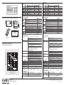
Interfaccia utente / User interface
Fig. 3
Caratteristiche elettriche dei contatti dei relè
Electrical specifications of the relay contacts
Fig. 4
Fig. 2
Dimensioni e posizionamento (mm) / Dimensions and positioning (mm)
64
74
75
33
montaggio a pannello
panel mounting
Sel
PRG
mute
comp
x100
dima di foratura
drilling template
71x29mm
fissaggio/overall dimensions 91.5x36.5mm
300
200
100
50
30
20
10
5
3
2
1
012345
corrente sui contatti (A)
contact current (A)
numero di operazioni (x 10
4
)
number of operation (x 10
4
)
120 Vac
250 Vac 30 Vdc
AC 120 V cosϕ= 0.7
AC 250 V cosϕ= 0.7
250 Vac cosϕ= 0.4
30 Vdc
120 Vac cosϕ= 0.4
30 Vdc
User interface
Green 3 digit display (plus sign and decimal point), amber operating signals and red alarm signal.
Symbol Colour Meaning Reference refrigerant
circuit
with LED on with LED flashing
1,2 Amber Compressor 1 and/or 2 On Startrequest 1
3,4 Amber Compressor 3 and/or 4 On Startrequest 2
Amber At least one compressor on 1 and/or 2
Amber Pump/air outlet fan on 1 and/or 2
Amber Condenser fan on 1 and/or 2
Amber Defrost active Defrostrequest 1 and/or 2
Amber Heater on 1 and/or 2
Red Alarm active 1 and/or 2
Amber Heat pump mode (P6=0) 1 and 2
Amber Chiller mode (P6=0) 1 and 2
Functions of the buttons
Button Unit status Button press mode
Loading default values Press at power on
Go up a sub-group inside the programming area, until exiting (saving changes to E2PROM) Press once
In the event of alarms, mute the buzzer (if present) and deactivate the alarm relay Press once
Access the direct parameters Press for 5 s
Select item inside the programming area and display value of direct parameters / confirm
the changes to the parameter
Press once
+
Program parameters after entering password Press for 5 s
Select top item inside the programming area Press once or press and hold
Increase value Press for 5 s
Switch from standby to chiller mode (P6=0) and vice-versa Press once or press and hold
Select bottom item inside the programming area Press once or press and hold
Decrease value Press for 5 s
Switch from standby to heat pump mode (P6=0) and vice-versa Press for 5 s
+
Manual alarm reset Press for 5 s
Immediately reset the hour counter (inside the programming area) Press for 5 s
+
Force manual defrost on both circuits Press for 5 s
Technical specifications
“Group A” is defined in the following specifications as the grouping of the following outputs: valve, pump, compressor, heater.
Power supply 24 Vac, range –15% ~ +10%; 50/60 Hz
Maximum current output: 3 W
Fuse to be fitted in series with the power supply of the μC2: 315 mAT
12-pin connector Max current 2 A for each relay output, extendable to 3 A for one output
Relays Max current at 250 Vac:
EN60730: Resistive: 3 A, Inductive: 2 A cos (ϕ)= 0.4 60000 cycles
UL:Resistive3A,1FLA,6LRAcos(ϕ)= 0.4 30000 cycles
For further information, refer to the characteristic shown in Fig. 5
Minimum interval between switching cycles (each relay): 12 s (the manufacturer of the unit that the
device is built into must ensure the correct configuration to respond to this specification)
Type of micro-switching of the relay: 1 C
Insulation between relays in group A: functional
Insulation between relays in group A and the very low voltage parts: reinforced
Insulation between relays in group A and the signal relay: primary
Insulation between the signal relay and the very low voltage parts: reinforced
Insulation between relays and the front panel: reinforced
Digital inputs ID1 to ID5, IDB4 Electrical standard: voltage-free contact
Closing current to ground: 5 mA
Maximum closing resistance: 50 W
Analogue inputs B1, B2, B3, B4: CAREL NTC temperature probes (10 kW at 25 °C)
The response time depends on the component used, typical value 90 s
B4: NTC temp. probes (10 kW at 25 °C) or CAREL 0 to 5 V or free contact ratiometric pressure probes
Fan output Control signal for CAREL MCHRTF****, CONVONOFF* and CONV0/10A* modules
Modulation of impulse position (set amplitude) or modulation of the duty-cycle. Refer to the user
manual for the configuration of the parameters
Loadless voltage: 5V ± 10%
Short-circuit current: 30 mA
Minimum output load: 1 kW
Front panel index of protection IP55
Storage conditions -10T70°C -- humidity 80% r.H., non-condensing
Operating conditions -10T50°C - humidity <90% r.H., non-condensing
Degree of pollution normal
Cat. of resist. to heat and fire D(UL94V0)
PTI of the insulating materials ≥ 250 V
Class and structure of the software A
Period of electrical stress across the
insulating parts
long
Note: All the relays must have the commons (C1/2, C3/4) connected together, as shown in Fig. 1.
Functional specifications
Resolution of analogue inputs Temperature probes: range -40T80°C, 0.1 °C
Temperature measurement error Range -20T20 °C, ±0.5 °C (excluding probe)
Range -40T80 °C, ±1.5 °C (excluding probe)
Pressure measurement error The voltage % error in the input range of 0.5 to 4.5 Vdc is ± 2% (excluding probe). The error in
the converted value may vary according to the setting of the parameters /9, /10, /11, /12 (see user
manual)
-
 1
1
-
 2
2


Carel MCH200*03 Assembly Instructions
- Categoria
- Termostati
- Tipo
- Assembly Instructions
- Questo manuale è adatto anche per
in altre lingue
- English: Carel MCH200*03
Documenti correlati
-
Carel Clima Manuale utente
-
-
-
-
-
Carel J3 Manuale utente
-
-
-
-