
pag. 1 / 8
MANUALE OPERATIVO / INSTRUCTION MANUAL
IM262-IU v0.1
ELR-4C
Relè differenziale di terra
multicanale 4 ingressi
ELR-4C
Multipoint earth leakage relay
4 inputs

pag. 2 / 8
CURRENTS
0.540 A
3.230 A
0.300 A
2.365 A
CORRENTI
0.540 A
3.230 A
0.300 A
2.365 A
ATTENZIONE!!!
• Leggere attentamente il manuale prima dell’utilizzo e l’installazione.
• Questi strumenti devono essere installati da personale qualificato, nel
rispetto delle vigenti normative impiantistiche, allo scopo di evitare danni
a persone o cose.
• Prima di qualsiasi intervento sullo strumento, togliere tensione dagli
ingressi di alimentazione e dalle uscite relè dove presenti.
• Il costruttore non si assume responsabilità in merito alla sicurezza
elettrica in caso di utilizzo improprio del dispositivo.
• I prodotti descritti in questo documento sono suscettibili in qualsiasi
momento di evoluzioni o di modifiche.
Descrizione
• Relè differenziale di terra tipo A
• Misure in vero valore efficace (TRMS)
• Filtro di terza armonica
• Esecuzione modulare, 3 moduli per guida DIN
• LED verde di segnalazione alimentazione (ON)
• Toroide esterno serie CT-1
• Funzionamento con sicurezza positiva per ciascun relè (impostabile)
• Visualizzazione dei valori della corrente differenziale
• Display LCD retroilluminato (verde, giallo, rosso)
• 4 LED per l’indicazione di TRIP
• Pulsanti TEST e RESET sul fronte
• 4 relè indipendenti per il controllo degli interruttori dei quattro canali
di ingresso
• Grafico andamento istantaneo della misura della corrente per ogni canale
• Log eventi intervento corrente di guasto
• Porta di comunicazione RS-485 (protocollo Modbus RTU)
Display and LED functions
Grazie al display LCD, l'utente può visualizzare i valori della corrente
differenziale, TRMS con filtro, valori MAX, TDH, fattore di cresta), grafici a
barre, Log eventi, gli allarmi e accedere alle impostazioni.
• Verde: corrente rilevata inferiore alla soglia impostata
• Giallo:
- rilevata corrente superiore alla soglia di PRE-ALLARME ma inferiore
alla soglia TRIP
- circuito aperto del toroide esterno (o non collegato)
• Rosso:
- intervento del relè di TRIP per il superamento della I∆n impostata
- lettura valore fuori scala
- TEST, provoca l’intervento del relè
Funzione dei tasti frontali
Tasto RESET – Serve per il ripristino dei relè dopo l‘intervento, per uscire dal
menu di impostazione.
Tasto TEST – Provoca l’intervento dei relè, per confermare una scelta.
Tasto PROG – Serve per entrare nel menu di impostazione, per lo
scorrimento delle pagine.
Tasti ▲e ▼– Servono per lo scorrimento fra le pagine video, per la
selezione tra le possibili scelte e per la modifica di impostazioni
(incremento/decremento).
WARNING!
• Carefully read the manual before the installation or use.
• This device is to be installed by qualified personnel, complying to current
standards, to avoid damages.
• Before any maintenance operation on the device, remove supply inputs.
• The manufacturer cannot be held responsible for electrical safety in case
of improper use of the equipment.
• Products illustrated herein are subject to alteration and changes without
prior notice.
Description
• Earth leakage relay type A
• Measuring in true effective value (TRMS)
• Third harmonic filtering
• Modular DIN-rail housing, 3 modules
• Green power LED indicator (ON)
• External residual current transfomer CT-1 series
• Fail safe function for each four relays (settable)
• Visualization instant leakage values
• Backlighted LCD display (green, yellow, red)
• 4 indicator LEDs for tripping
• On the front panel, TEST and RESET button
• Four independent relays to control the circuit breakers of the four
channels
• Instantaneous bar-graph of current measurement for each channel
• Log tripped residual current
• RS-485 communication (Modbus RTU protocol)
Display and LED functions
Thanks to LCD display, the user can view very quickly the measurements
(instant leakage values, filter TRMS, MAX values, THD, crest factor), the
graph bar, the Log, the alarms and can access to all settings.
• Green: detected current lower than threshold
• Yellow:
- detected current higher than PRE-ALARM threshold but lower than
TRIP threshold
- open residual current transformer circuit (or not connected)
• Red:
- detected current higher than TRIP threshold and relay activation
- current leakage read off scale
- TEST, causes tripping of the relay
Front keyboard
RESET key – To reset the relay after tripping, used to exit from settings
menu.
TEST key – Causes tripping of the relays, to confirm a choice.
PROG keys – Used to enter into settings menu, to scroll display pages.
▲and ▼ keys – Used to switch between visualization modes, to select
among possible choices and to modify settings (increment/decrement).
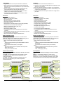
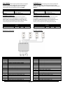
LED ON: presence of
auxiliary voltage
LCD display instant
leakage current, TRMS
values, MAX values, THD
values, crest factor, LOG
and channel’s settings
TEST pushbutton
RESET pushbutton
PROG (▲and ▼ keys)
used to enter menu settings
TRIP LED inputs 1 - 4
▲and ▼ keys used to
switch between
visualization
Channel input indication
LED ON: indica la presenza
della tensione ausiliaria
LCD display instant
leakage current, TRMS
values, MAX values, THD
values, crest factor, LOG
and channel’s settings
Pulsante TEST
Pulsante RESET
PROG (▲e ▼) usato per
accedere al menu
impostazioni
TRIP LED ingressi 1 - 4
Tasti ▲e ▼ usati
per lo scorrimento
fra le pagine
Indicazione canale ingresso

pag. 3 / 8
CURRENTS
0.540 A
3.230 A
0.239 A
2.367 A
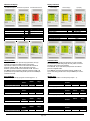
Indicazioni sul display
Visualizzazione regolare Visualizzazione pre-allarme Visualizzazione intervento
Causa dell’intervento
Messaggio sul display
Test
/ Display rosso
Corrente differenziale
/ Display rosso
Altri messaggi sul display
Lettura valore fuori scala
OVR
Errore connessione con sensore
OPEN
Tabella parametri
Di seguito sono elencati tutti i parametri di programmazione. Per ogni
parametro sono indicati il possibile intervallo di impostazione,
l'impostazione di fabbrica, nonché una descrizione della funzione del
parametro. Premere i tasti ▲ e ▼ per selezionare il parametro
desiderato. Il parametro selezionato è evidenziato con ►. Premere il
tasto TEST per attivare il parametro selezionato. Utilizzare i tasti ▲ e ▼
per selezionare tra le possibili scelte possibili e premere il tasto TEST per
confermare una scelta.
Menu INGRESSI
Configurazione parametri per gli ingressi di corrente (ingressi 1…4).
CORRENTE DI GUASTO
Unità di
misura
Default
Range
I∆
mA
30
30…30000
Definisce la soglia di intervento per corrente di guasto verso terra.
TEMPO D’INTERVENTO
Unità di
misura
Default
Range
Tempo
ms
20
20…10000
Definisce il tempo ritardo di intervento.
FILTRO 3° ARMONICA
Unità di
misura
Default
Range
Filtro
-
OFF
ON-OFF
Se impostato ad ON, si abilita il filtro di blocco per la 3a armonica.
TEMPO PRE-ALARM
Unità di
misura
Default
Range
Tempo
ms
20
20…10000
Definisce il tempo di ritardo del pre-allarme.
Display indications
Correct display Pre-alarm display Trip display
Cause of the trip
Display message
Test
/ Red display
Current leakage
/ Red display
Others display messages
Current leakage over scale
OVR
Poor toroidal connection
OPEN
Parameters table
Below are listed all the programming parameters. For each parameter
are indicated the possible setting range, the factory default, as well as a
description of the function of the parameter.
Press ▲and ▼ keys to select the required parameter. The selected
parameter is highlited with ►.
Press TEST key to activated the selected parameter. Use ▲and ▼
keys to select among possible choices and press TEST key to confirm a
choice.
INPUTS menu
Configuration parameters for current inputs (for inputs 1…4).
FAULT CURRENT
Unit of
measure
Default
Range
I∆
mA
30
30…30000
Select the tripping fault current to earth.
TRIPPING DELAY TIME
Unit of
measure
Default
Range
Time
ms
20
20…10000
Select the tripping delay time.
3
RD
HARMONIC FILTER
Unit of
measure
Default
Range
3RD filter
-
OFF
ON-OFF
Set to ON if the harmonic blocking filters for 3rd harmonic is used.
PRE-ALARM DELAY TIME
Unit of
measure
Default
Range
Time
ms
20
20…10000
Select the pre-alarm delay time.
CURRENTS
0 . 5 4 0 A
3 . 2 3 0 A
0.300 A
2 . 3 6 5 A
C O RRENTI
0 . 5 4 0 A
3 . 2 3 0 A
0.300 A
2 . 3 6 5 A
C O RRENTI
0 . 986 A
5 .200 A
0 . 732 A
4 . 500 A
C U RRENT S
0 . 986 A
5 .200 A
0 . 732 A
4 . 5 00 A
C O RRENTI
0 . 6 0 2 A
4 . 023 A
0 . 690 A
3 . 934 A
C U RRENTS
0 . 6 0 2 A
4 . 023 A
0 . 690 A
3 . 934 A
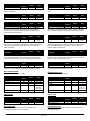
BAR GRAPH
THD
36.0 %
3 7 . 0 %
3 7 . 0 %
3 5 . 0 %
10 : 37 : 00
27 / 05 / 2 0 1 9
09 : 37 : 00
27 / 05 / 2 0 1 9
08 : 37 : 00
27 / 05 / 2 0 1 9
16 : 37 : 00
27 / 05 / 2 0 1 9
LOG
BAR GRAPH
THD
36.0 %
3 7 . 0 %
3 7 . 0 %
3 5 . 0 %
LOG
10 : 37 : 00
27 / 05 / 2 0 1 9
09 : 37 : 00
27 / 05 / 2 0 1 9
08 : 37 : 00
27 / 05 / 2 0 1 9
16 : 37 : 00
27 / 05 / 2 0 1 9

pag. 4 / 8
SOGLIA PRE-ALARM
Unità di
misura
Default
Range
%
%
70
20…100
Definisce la soglia di pre-allarme che è in funzione del valore della corrente
di guasto di intervento.
ISTERESI
Unità di
misura
Default
Range
Isteresi
%
120
105…150
Definisce l’isteresi per la soglia di corrente di guasto di intervento.
TRIP RELE’ FAILSAFE
Unità di
misura
Default
Range
Failsafe
-
OFF
ON-OFF
Se impostato su ON, sicurezza positiva attivata sul relè TRIP dell'ingresso
del canale, in questa condizione il relè TRIP è normalmente eccitato;
pertanto, in caso di mancanza di tensione ausiliaria, i contatti di uscita si
spostano nella condizione di scatto.
RESET TRIP
Unità di
misura
Default
Range
Reset
-
MAN
AUTO-MAN-
REC
Se impostato su AUTO, il reset di TRIP sarà automatico. Se impostato su
MAN, ripristino manuale tramite il tasto RESET o da remoto. Se impostato su
REC, viene eseguito un ripristino automatico fino al numero massimo di
richiusure impostate.
FUNZIONE MEMORIA
LAST TRIP
Unità di
misura
Default
Range
F.M.T.
s
10
10…600
Nella condizione di intervento, se il dispositivo viene disalimentato e
successivamente rialimentato, verrà visualizzato, per il tempo impostato, il
numero dell'ingresso ed il valore della corrente all'intervento (LAST TRIP).
RESET PRE-ALARM
Unità di
misura
Default
Range
Reset
-
AUTO
AUTO-MAN
Se impostato su AUTO, il ripristino del pre-allarme sarà automatico. Se
impostato su MAN, ripristino manuale tramite il tasto RESET sul frontale.
Menu COMUNICAZIONE
Parametri porta di comunicazione (COM1).
RS485
Unità di
misura
Default
Range
Indirizzo nodo seriale
-
01
01-247
Baudrate
bps
38400
4800-115200
Bit di stop
-
1
1-2
Fomato dati
-
8 bit - n
8 bit, no parity
8 bit, odd
8 bit, even
Tempo di risposta
ms
10
5-100
Menu UTILITA’
UTILITA’
Unità di
misura
Default
Range
Lingua
-
ENG
ENG-ITA
Frequenza di lavoro
Hz
50
50-60
Menu DATA e ORA
L’ELR-4C gestisce un orologio datario che viene utilizzato per la
memorizzazione degli eventi (corrente di guasto).
PRE-ALARM THRESHOLD
Unit of
measure
Default
Range
%
%
70
20…100
Select the pre-alarm threshold which is a function of the tripping fault current
value.
HYSTERESIS
Unit of
measure
Default
Range
Hysteresis
%
120
105…150
Tripping fault current threshold hysteresis.
TRIP RELAY FAILSAFE
Unit of
measure
Default
Range
Failsafe
-
OFF
ON-OFF
If set to ON, positive safety activated on TRIP relay of the channel input, in
this condition the TRIP relay is normally energised; therefore in the event of
the lack of auxiliary voltage the output contacts move to the trip condition.
RESET TRIP
Unit of
measure
Default
Range
Reset
-
MAN
AUTO-MAN-
REC
If set to AUTO, the reset of TRIP will be automatic. If set to MAN, manual
reset through the RESET key on the front. If set to REC, enables the device
to reconnect fault signaling, that is performed an automatic reset up to
maximum number of reclosures set.
FUNCTION MEMORY
LAST TRIP
Unit of
measure
Default
Range
F.M.T.
s
10
10…600
In the tripping condition, if the device is powered off and subsequently
powered on again, will be displayed, for the set time, the input number and
the value of the trip fault current (LAST TRIP).
RESET PRE-ALARM
Unit of
measure
Default
Range
Reset
-
AUTO
AUTO-MAN
If set to AUTO, the reset of pre-alarm will be automatic. If set to MAN,
manual reset through the RESET key on the front.
COMMUNICATION menu
Communication port parameters (COM1).
RS485
Unit of
measure
Default
Range
Serial node address
-
01
01-247
Baudrate
bps
38400
4800-115200
Stop bits
-
1
1-2
Data format
-
8 bit - n
8 bit, no parity
8 bit, odd
8 bit, even
Response time
ms
10
5-100
UTILITY menu
UTILITY
Unit of
measure
Default
Range
Language
-
ENG
ENG-ITA
Operating frequency
Hz
50
50-60
TIME and DATE menu
The ELR-4C manages the time and date, that is used for the storage of
events (tripped current).

pag. 5 / 8
Menu COMANDI
Il menu comandi permette di eseguire operazioni saltuarie quali ripristino
impostazioni, azzeramento memoria eventi. Una volta selezionato il
comando desiderato, premere TEST per eseguirlo. Per annullare
l’esecuzione del comando selezionato, premere il tasto RESET.
RESET
Descrizione
Parametri a default
Ripristina tutte le impostazioni ai valori di
default di fabbrica
Reset log
Azzera la lista di eventi
PASSWORD ACCESS menu
La password serve per abilitare o sbloccare l’accesso al menu di
impostazione ed al menu comandi (RESET). Per i dispositivi nuovi di
fabbrica (default), la password è disabilitata e l’accesso è libero. Se
invece la password è stata abilitata ed impostata (0-9999), per ottenere
l’accesso bisogna prima inserire il relativo codice di accesso.
PASSWORD
Unità di
misura
Default
Range
Valore
-
0
0-9999
Se impostato a 0, la gestione della password è disabilitata.
Morsettiere di connessione
N°
Descrizione
1
Contatto di uscita allarme R1
2
Contatto di uscita allarme R1,R2 (COMUNE)
3
Contatto di uscita allarme R2
4
Contatto di uscita allarme R3
5
Contatto di uscita allarme R3,R4 (COMUNE)
6
Contatto di uscita allarme R4
7
TEST a distanza (DI1)
8
Comune ingressi digitali (COMUNE)
9
RESET a distanza (DI2)
10
Alimentazione ausiliaria (fase o neutro)
11
Non utilizzato
12
Alimentazione ausiliaria (neutro o fase)
13
Ingresso per sensore corrente toroidale 4-S1
14
Ingresso per sensore corrente toroidale 3,4-S2
15
Ingresso per sensore corrente toroidale 3-S1
16
Ingresso per sensore corrente toroidale 2-S1
17
Ingresso per sensore corrente toroidale 1,2-S2
18
Ingresso per sensore corrente toroidale 1-S1
COMMANDS menu
The commands menu allows executing some occasional operations like
resetting, log events clearing. Once the required command has been
selected, press TEST to execute it. To cancel the command execution press
RESET key.
COMMAND
Description
Parameters to default
All setup parameters are resetted to
factory default value
Reset log
Clears the event log memory
PASSWORD ACCESS parameters table
The password is used to enable or lock to setting menu and command
menu (RESET). For new devices (factory default), the password
management is disabled and the access is free. If instead the password
has been enabled and defined (0-9999), then to get access, it’s
necessary to enter the password first, specifyng the number code.
PASSWORD
Unit of
measure
Default
Range
Value
-
0
0-9999
If set to 0, password management is disabled.
Terminals connection
N°
Description
1
Trip output relay R1
2
Trip output relay R1,R2 (COMMON)
3
Trip output relay R2
4
Trip output relay R3
5
Trip output relay R3,R4 (COMMON)
6
Trip output relay R4
7
External TEST (DI1)
8
Digital input (COMMON)
9
External RESET (DI2)
10
Auxiliary supply (neutral or phase)
11
Not used
12
Auxiliary supply (neutral or phase)
13
Input toroidal current transformer 4-S1
14
Input toroidal current transformer 3,4-S2
15
Input toroidal current transformer 3-S1
16
Input toroidal current transformer 2-S1
17
Input toroidal current transformer 1,2-S2
18
Input toroidal current transformer 1-S1

pag. 6 / 8
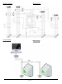
Schema di connessione
Connessione RS485
Wiring connection
RS485 connection
1 2 3 4 5 6 7 8 9
10 11 12 13 14 15 16 17 18

pag. 7 / 8
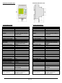
Dimensioni meccaniche (mm)
Caratteristiche tecniche
Circuito di controllo
Toroide
Esterno, serie CT-1
Tipologia d’intervento
Tipo A
Set-point intervento (I∆)
0,03÷30A
Set-point preallarme
20÷100%
Tempo di intervento (t)
0,02÷10s
Ripristino
Automatico o manuale con pulsante
frontale o remoto
Alimentazione ausiliaria
Tensione ausiliaria
230VCA ±20%
Frequenza nominale
50/60Hz
Potenza massima assorbita
6VA
Uscite relè
Uscite
4
Stato del relè
Impostabile normalmente diseccitati
oppure normalmente eccitati
Tensione nominale di lavoro
250VCA
Corrente nominale
6A (max 10A)
Vita meccanica
10 · 10
6
cicli
Display
Tecnologia
LCD
Interfaccia seriale RS485
Protocollo
Modbus-RTU
Baud-rate
Programmabile 4800 – 115200 bps
Connessioni
Tipo di morsetti
A vite (fissi)
N° morsetti
18
Sezione conduttori
0,127 - 2,082 mm
2
Coppia di serraggio mors.
0.5 - 0.6 Nm
Lunghezza cavo sguainato
7mm
Condizioni ambientali di funzionamento
Temperatura di impiego
-10÷60°C
Temperatura di stoccaggio
-20÷80°C
Umidità relativa
5÷95%
Contenitore
Esecuzione
3 moduli DIN
Grado di protezione
IP20 sui morsetti
IP40 sul frontale
Peso
200g
Conformità
Norme di riferimento
EN 61010, EN 61000-6-2,
EN 61000-6-3, IEC/TR 60755
EN 60947-2 Annex M
Mechanical dimensions (mm)
Technical characteristics
Control circuit
Toroidal transformer
External, CT-1 series
Tripping type
Type A
Tripping set-point (I∆)
0,03÷30A
Prealarm set-point
20÷100%
Tripping time (t)
0,02÷10s
Resetting
Automatic or manual by pushbutton on
front or remote
Auxiliary supply
Auxiliary voltage
230VAC ±20%
Rated frequency
50/60Hz
Max power consumption
6VA
Output relay
Number of outputs
4
State
Configurable normally de-energised
or energised
Rated operating voltage
250VAC
Rated current
6A (max 10A)
Mechanical life
10 · 10
6
cycles
Display
Type
LCD
RS485 serial interface
Protocol
Modbus-RTU
Baud-rate
Programmable 4800 – 115200 bps
Connections
Type of terminal
Screw (fixed)
Number of terminals
18
Conductor cross section
0,127 - 2,082 mm
2
Tightening torque
0.5 - 0.6 Nm
Length of cable to strip
7mm
Ambient operating conditions
Operating temperature
-10÷60°C
Storage temperature
-20÷80°C
Relative humidity
5÷95%
Housing
Version
3 module DIN
Degree of protection
IP20 terminals
IP40 on front
Weight
200g
Certifications and compliance
Reference standards
EN 61010, EN 61000-6-2,
EN 61000-6-3, IEC/TR 60755
EN 60947-2 Annex M
1 2 3 4 5 6 7 8 9
10 11 12 13 14 15 16 17 18

pag. 8 / 8
Per ulteriori informazioni contattare:
Contrel elettronica s.r.l.
Via San Fereolo, 9
I-26900 Lodi
Tel: +39 0371 30207 / 30761 / 35386
Fax: +39 0371 32819
E-Mail: [email protected]
www.contrel.it
For further details please contact:
-
 1
1
-
 2
2
-
 3
3
-
 4
4
-
 5
5
-
 6
6
-
 7
7
-
 8
8


in altre lingue
- English: Contrel ELR-4C User manual
Altri documenti
-
 CET LFP41 Manuale del proprietario
-
CARLO GAVAZZI WM4096 Manuale utente
-
-
ABB RED650 Applications Manual
-
Woodward easYgen-1800 Manuale utente
-
-
-
ABB REL650 series Applications Manual
-
-
 Chemitec 4222 Technical Manual

