Metrologic IS4320 ScanGlove Programming Manual
- Tipo
- Programming Manual

METROLOGIC INSTRUMENTS, INC.
IS4320 ScanGlove
Programming Guide
MLPN 2405
Printed in USA
April 1998

ii
Locations:
USA Corporate Headquarters Europe
Metrologic Instruments, Inc. Metrologic Instruments GmbH
Blackwood, NJ 08012 Munich, Germany
Customer Service: 1-800-ID-METRO Tel: 49-89-89018-0
Tel: 609-228-8100 Fax: 49-89-89019-200
Fax: 609-228-6673
ASIA
South America
Metrologic Asia (PTE) Ltd.
Metrologic Instruments Singapore 417818
CEP 04571-090, São Paulo-SP, Brasil Tel: 65-842-7155
Outside Brazil: Fax: 65-842-7166
Tel: 55-11-5505-6568
Fax: 55-11-5505-1681
In Brazil:
Tel: 55-11-5505-2396
Fax: 55-11-5507-2301
Copyright
© 1998 by Metrologic Instruments, Inc. All rights reserved. No part of this work may
®
be reproduced, transmitted, or stored in any form or by any means without prior written
consent, except by reviewer, who may quote brief passages in a review, or provided for
in the Copyright Act of 1976.
Products and brand names mentioned in this document are trademarks of their
respective companies.

iii
Table of Contents
Programming the Scanner ........................................ 1
Enter Program Mode ............................................ 2
Recall Defaults................................................. 2
Laser Activation Range .......................................... 3
Laser Operation ................................................ 4
Same Symbol Re-Scan .......................................... 5
Beeper Tones.................................................. 6
Audible Indicators for Communication Timeouts...................... 7
RS-232 Interface ............................................... 8
RS-232 Parameter - Baud Rate .................................. 8, 9
RS-232 Parameter - Parity ...................................... 10
RS-232 Parameter - Data Bits .................................... 11
RS-232 Parameter - Hardware Handshaking ........................ 12
RS-232 Parameter - Software Handshaking ......................... 13
RS-232 Parameter - Intercharacter Delay ........................... 14
RS-232 Parameter - Scanning Control (DTR Signal) ................. 15
Record Header/Terminator Select.............................. 15-17
RS-232 Parameter - UPC/EAN Identifiers .......................... 18
Light Pen Options ............................................. 19
Code Type Selections ....................................... 20, 21
Minimum Code Length for All Code Types ......................... 22

iv
UPC/EAN Code............................................... 22
UPC-A Options ............................................... 23
UPC-E Options ............................................... 24
Supplemental UPC Options ..................................... 25
Code 39 .................................................. 26, 27
Codabar ..................................................... 27
Interleaved 2 of 5 (ITF) ......................................... 28
Interleaved 2 of 5 (ITF) Symbol Lengths ........................ 29-32
MSI - Plessey Check Digit ................................... 32, 33
Test Modes................................................... 34
Special Features............................................ 35, 36
Reserved Codes ............................................ 37-41
Disclaimer ................................................... 42
Index .................................................... 43, 44

**
1
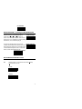
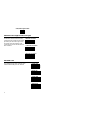
Programming the Scanner
The IS4320 is shipped from the factory programmed to a set of default
parameters. Defaults are noted in the following pages by double asterisks next
to the bar code labels. Modifications to the default program to match the host
system are made using bar codes contained in this manual.
1. Connect the scanner to the host system or power source. (Refer to the
Installation and User’s Guide.)
2. Scan the ENTER/EXIT PROGRAM MODE bar code. (The unit will
beep three times.)
3. Scan by positioning the output window within two inches of each code.
(When you scan the first menu selection, the laser will stay on until you
scan the ENTER/EXIT PROGRAM MODE code again. If no scanning
occurs for 30 seconds while the scanner is in program mode, the unit
will beep three times and all changes made will be lost. If this occurs,
return to Step 1.)
4. After completing the scanning of the appropriate configuration options,
scan the ENTER/EXIT PROGRAM MODE bar code again. (The new
options will be saved and the scanner is ready for normal operation.)
Enter/Exit
Program Mode

**
R18
R19
DF1
Enter/Exit Program Mode
2
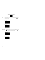
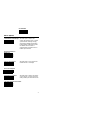
Enter Program Mode
**Ability to Enter Program
When this option is selected, enter
Mode After Any Scan
programming by scanning the
ENTER/EXIT PROGRAM MODE bar
code after power up or during normal
scanning operation.
Enter Program Mode Only
When this option is selected, the scanner
on First Scan
will only enter program mode after power-
up. Scan the ENTER/EXIT PROGRAM
MODE bar code immediately after the
scanner first receives power. This option
prevents the scanner from accidentally
entering program mode during normal
scanning operation.
Recall Defaults
If during programming of the scanner, there is a need to return the scanner to
the original factory settings, scan the RECALL DEFAULTS bar code. Any
settings selected during that session or any previous session will be lost.
Recall Defaults

DF1
RS1
RS3
RS2
RS4
Recall Defaults
3
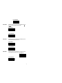
Laser Activation Range
Short Range Activation
When this option is selected, the IR
Out of the Stand
sensor guarantees to activate when the
scanning window is positioned three
inches from the object.
Short Range Activation
When this option is selected, the IR
In the Stand
sensor guarantees to activate when an
object is presented three inches from
the scanning window.
**Long Range Activation
When this option is selected, the IR
Out of the Stand
sensor guarantees to activate when the
scanning window is positioned eight
inches from the object.
**Long Range Activation
When this option is selected, the IR
In the Stand
sensor guarantees to activate when an
object is presented eight inches from
the scanning window.

**
RS5
RS6
LP8
Enter/Exit Program Mode
4
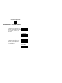
Laser Operation
**Normal Scan
This option is the default setting. When the laser
activates by the IR sensor, the laser beam will emit
from the output window. It will also display a
constant, horizontal line until it senses a bar code
or until the scanner timeout elapses.
Pulsing Scan
When the laser activates by the IR sensor, the laser
beam will emit from the output window. It will also
display a pulsing, horizontal line until it senses a
bar code or until the scanner timeout elapses.
Custom Scan
This option is available for special applications.
Do not scan the CUSTOM SCAN bar code unless
instructed by a Metrologic representative.

DF1
R30
R31
Recall Defaults
5
Same Symbol Re-Scan
The scanner is programmed with a same symbol
Short Same
timeout. For SHORT SAME SYMBOL RE-SCAN,
Symbol Re-Scan
the time delay is ½ second, while the LONG SAME
SYMBOL RE-SCAN delay is 1 second. These numbers
represent the amount of time that a bar code must be out of
the scan field before it can be scanned again.
** Long Same Symbol Re-Scan

**
BP1
BP2
BP3
BP4
Enter/Exit Program Mode
6
Beeper Tones
Program the scanner to emit a certain tone.
Alternate Tone 1 ................................. Low Tone
Alternate Tone 2 ................................. High Tone
(Default)
Alternate Tone 3 ................................. Medium Tone
No Tone
Alternate Tone 1
**Alternate Tone 2
Alternate Tone 3
No Tone

DF1
OC5
OC6
OC7
OC8
OC9
R50
R51
Recall Defaults
7
Audible Indicators for Communication Timeouts
Two Second Timeout
When this option is selected, the scanner will
timeout if it does not transmit its data to the
host after two seconds during communica-
tion. This is only valid in modes where some
type of hand-shaking is involved.
**No Two Second Timeout
Razz Beep on Timeout
When this option is selected, The scanner
will produ ce an audible razzberry tone
when communications timeout.
** No Tone After Timeout
Three Beep on Timeout
When this option is selected, the scanner will
beep three times when communications time-
out.
** Beep Before Transmit
When this option is selected, the scanner will
beep before each label transmits.
Beep After Transmit
When this option is selected, the scanner will
beep after each label transmits.

**
LP2
BR1
BR2
BR3
BR4
Enter/Exit Program Mode
8
RS-232 Interface
** Enable RS-232 Interface
RS-232 Parameter - Baud Rate
A baud rate is a unit that measures the speed with which information transfers.
The baud rate of the scanner must equal the baud rate of the host device. The
available baud rates range from 150 to 19200.
150 Baud Rate
300 Baud Rate
600 Baud Rate
1200 Baud Rate

DF1
BR5
BR6
BR7
BR8
Recall Defaults
9
2400 Baud Rate
4800 Baud Rate
** 9600 Baud Rate
19200 Baud Rate

**
PA1
PA3
PA2
PA4
Enter/Exit Program Mode
10
RS-232 Parameter - Parity
Parity is an additional digit that makes the number of bits in the ASCII code
odd or even. The scanner’s parity must match the host’s parity.
**Space Parity
Select this option to make the parity bit always 0.
Even Parity
Select this option to make the additional parity bit
either a 0 or 1 to guarantee an even number of bits.
Mark Parity
Select this option to make the parity bit always 1.
Odd Parity
Select this option to make the additional parity bit
either a 0 or 1 to guarantee an odd number of bits.

DF1
D81
D82
Recall Defaults
11
RS-232 Parameter - Data Bits
RS-232 serial communication requires ASCII data to
8 Data Bits
transmit in either 7 or 8 data bits. In addition, one parity
bit will transmit. If necessary, scan the appro-priate bar
code that matches your host device’s requirements.
** 7 Data Bits

**
HH1
HH2
R56
R57
Enter/Exit Program Mode
12
RS-232 Parameter - Hardware Handshaking
To prevent scanned information from being lost during
Enable RTS/CTS
transmission, your host device may require an RTS/
CTS signal. When RTS/CTS (R
eady To Send/Clear To
S
end) enables, the scanner will output an RTS signal
and wait for a CTS signal before any data transmits. The
default setting of RTS/CTS disables. If necessary, scan
the ENABLE RTS/CTS bar code.
** Disable RTS/CTS
** Character RTS/CTS
When this option is selected, the scanner will
activate and deactivate its RTS signal on each
character that it transmits.
Message RTS/CTS
When this option is selected, the scanner will
activate and deactivate its RTS signal on each
message that it transmits. This mode should
normally enable for Sanyo registers.

DF1
SH2
SH1
SH4
SH3
Recall Defaults
13
RS-232 Parameter - Software Handshaking
For control of the data transmission process, use the following parameters
instead of or in addition to the RTS/CTS hardware handshaking option.
ACK/NAK When this option is enabled,the
Enable ACK/NAK
scanner will not scan again unless
after transmission of a bar code it
receives an ACK (ASCII 06H).
The scanner will retransmit the
bar code, if it receives an NAK
(ASCII 15H).
** Disable ACK/NAK
XON/XOFF When this option is enabled, the
Enable XON/XOFF
scanner will stop transmission
whenever it receives an XOFF
(ASCII 13H). Transmission will
resume after it receives an XON
(ASCII 11H).
**DisableXON/XOFF

**
R20
R21
R22
R23
Enter/Exit Program Mode
14
RS-232 Parameter - Intercharacter Delay
The time specified with an intercharacter delay bar code represents the interim
of time between transmission of characters. Some host systems require this
delay when receiving transmissions. If necessary, scan the appropriate bar
code.
** No Intercharacter Delay
1 Millisecond Intercharacter Delay
5 Millisecond Intercharacter Delay
25 Millisecond Intercharacter Delay

DF1
HH3
HH4
R32
TR1
TR2
Recall Defaults
15
RS-232 Parameter - Scanning Control (DTR Signal)
When the DTR (Data Terminal Ready) input is
Enable DTR Input
enabled, the scanner will not transmit unless an
active (+12V) DTR signal is present on the scanner’s
DTR input pin. You can disable the scanner by making
DTR inactive (-12V) at the DTR input pin.
The DTR Scan Disable feature will prevent any
** Disable DTR Input
scanning when the Enable DTR input feature is chosen.
Before enabling the Enable DTR Scan Disable feature,
scan the Enable DTR Input bar code. To turn off this
feature, scan the Recall Defaults bar code.
Enable DTR Scan Disable
Record Header/Terminator Select
CR
When this option is on, the scanner will transmit a C
arriage
R
eturn after each bar code.
CR Off
**CR On

**
TR4
TR3
TR6
TR5
Enter/Exit Program Mode
16
LF
When this option is on, the scanner will transmit a L
ine Feed
after each bar code.
**
LF On
LF Off
STX Prefix
When this option is on, the scanner will transmit a S
tart of
T
eXt (ASCII 02H) before each bar code.
STX Prefix On
** STX Prefix Off
La pagina sta caricando ...
La pagina sta caricando ...
La pagina sta caricando ...
La pagina sta caricando ...
La pagina sta caricando ...
La pagina sta caricando ...
La pagina sta caricando ...
La pagina sta caricando ...
La pagina sta caricando ...
La pagina sta caricando ...
La pagina sta caricando ...
La pagina sta caricando ...
La pagina sta caricando ...
La pagina sta caricando ...
La pagina sta caricando ...
La pagina sta caricando ...
La pagina sta caricando ...
La pagina sta caricando ...
La pagina sta caricando ...
La pagina sta caricando ...
La pagina sta caricando ...
La pagina sta caricando ...
La pagina sta caricando ...
La pagina sta caricando ...
La pagina sta caricando ...
La pagina sta caricando ...
La pagina sta caricando ...
La pagina sta caricando ...
-
 1
1
-
 2
2
-
 3
3
-
 4
4
-
 5
5
-
 6
6
-
 7
7
-
 8
8
-
 9
9
-
 10
10
-
 11
11
-
 12
12
-
 13
13
-
 14
14
-
 15
15
-
 16
16
-
 17
17
-
 18
18
-
 19
19
-
 20
20
-
 21
21
-
 22
22
-
 23
23
-
 24
24
-
 25
25
-
 26
26
-
 27
27
-
 28
28
-
 29
29
-
 30
30
-
 31
31
-
 32
32
-
 33
33
-
 34
34
-
 35
35
-
 36
36
-
 37
37
-
 38
38
-
 39
39
-
 40
40
-
 41
41
-
 42
42
-
 43
43
-
 44
44
-
 45
45
-
 46
46
-
 47
47
-
 48
48


Metrologic IS4320 ScanGlove Programming Manual
- Tipo
- Programming Manual
in altre lingue
- English: Metrologic IS4320 ScanGlove
Documenti correlati
-
Metrologic MS951 Programming Manual
-
-
-
-
-
-
-
-