Fiveo F82CX Manuale del proprietario
- Categoria
- Controller DJ
- Tipo
- Manuale del proprietario

EN The information contained in this manual have been carefully drawn up and
checked However no responsibility wi/l be assumed for any incorrectness. This
manual cannot cover all the possible contingencies which may arise during the
product installation and use. Should further information be desired, please contact
us or our local distributor Elettronica Montarbo srl can not be considered responsible
for damages which may be caused to people and things when using this product.
Specifications and features are subject to change without prior notice
EN
OWNER’S
MANUAL

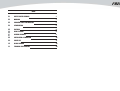
INDEX
01
0101
01 SAFETY RELATED SYMBOLS
1
02
0202
02 WARNING
1
03
0303
03 IMPORTANT SAFETY INSTRUCTION 2
04
0404
04 INTRODUCTION
3
05
0505
05 FEATURES
3
06
0606
06 READY TO START
3
07
0707
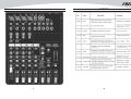
07 CONTROL ELEMENTS 4
08
0808
08 INSTALLATION & CONNECTION 14
09
0909
09 PRESET LIST 17
10
1010
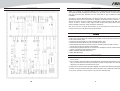
10 BLOCK DIAGRAM 18
11
1111
11 TECHNICAL SPECIFICATION 19

20 1

2 19
F82CX

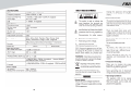
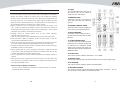
INTRODUCTION
Thank you choosing for purchasing F82CX. This is a professional compact mixer to give you
great quality and better reliability than ever before you will get the smooth, accurate more natural
and open sound from this apparatus and it is really ideal for gigs, recording and fixed PA
installations.
The F82CX is packed with features that can not be found in other consoles of its size: 2 mono
(provided with ultra low noise microphone pre amplifiers and Phantom Power at +48 Volt ) and 3
stereo input channels and each of them is provided with a 3-band equalizer for HI, MID and LOW
controls, as well as auxiliary control; highly accurate 8-segment bar graph meters and 2-track
inputs assignable to main mix, control room/phones Outputs etc.
This unit is very easy to operate but we advise you to go through each section of this manual
carefully. In this way you will get the best out of your F82CX.
FEATURES
Ultra-low noise discrete MIC Preamps with +48V Phantom Power.
2 MIC Input Channels with XLRs and balanced Line Inputs, and Insert I/O and Compressor control.
Low Cut for each MIC Input
2 Stereo Input Channels with mono XLR Input and 1/4"TRS Jacks.
1 Stereo Input Channel with RCA Jacks and 1/4"TRS Jacks inputs.
3-band EQ and Peak LEDs on each MIC channels. 2-band EQ and Peak LEDs on Stereo
channels. DFX sends per channel for internal effects.
2-Track Input assignable to Main Mix or Control Room / Headphone Outputs. Unbalanced 1/4"TRS
outputs, Control Room and Headphone Outputs.
Built in 24-bit DSP effect with 100 presets.
Option: MP3 Rec/Player.
READY TO START
1.
Please check the AC voltage available in your country before connecting your AC ADAPTOR to
the AC socket.
2.
Be sure that the main power switch is turned off before connecting the mixer to the AC socket.
Also, you should make sure that all input and output controls are turned down. This will avoid
damage to your speakers and avoid excessive noise.
3.
Always turn on the mixer before the power amplifier; turn off the mixer after the power amplifier.
4.
Before connecting and disconnecting the unit from the power source always turn off the unit.
5.
Do not use solvents to clean your mixer. A dry and clean cloth will be OK
BLOCK DIAGRAM
18 3

CONTROLL
I
PRESET
LIST
4 17

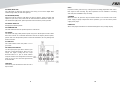
1.
MIC INPUT JACKS (CHs1 to 5/6)
These are balanced XLR-type microphone input
jacks
2. LINE INPUT JACKS (CHs 1,2)
These are balanced TRS phone-jack line inputs.
You can connect either balanced or unbalanced
phone plugs to these jacks
3. LINE INPUT JACKS (CHs 3/4 to 7/8 (Chs 3/4
to 9/10))
These are unbalanced phone-jack stereo line
inputs.
4. LINE INPUT JACKS (CH 7/8, (CHs 7/8, 9/10))
These are unbalanced stereo RCA pin jacks.
NOTE:
Where an input channel provides both a MIC input jack and a LINE input jack, or a LINE
input jack and an RCA pin jack, you can use either jack but not both at the same time. Please
connect to only one jack on each channel.
5. INSERT JACKS
Each of these jacks provides an insert point between the equalizer and level control of
the corresponding input channel, The INSERT jacks can be used to independently connect
devices such as graphic equalizers, compressors, or noise filters into the corresponding
channels. These are TRS phone jacks that carry both the send and return signal.
6. GAIN CONTROL
Adjusts the input signal level. To achieve the best balance betweenS/N and dynamic range,
adjust the level so that the peak LED indicator lights occasionally only on the highest input
transients. For mono channel the MIC input adjustment range of the Gain is 0 to 50dB and the
sensitivity of line input is +15 to -35dB; For stereo channel the MIC adjustment range of the Gain
is 0 to 40dB and the sensitivity of line input is +20 to -20dB.
7. LOW CUT
By pressing this button you will activate a 75Hz low frequency filter with a slope of 18dB per
octave. You can use this facility to reduce the hum noise infected by the mains power supply. Or
the stage rumble while using a microphone.
16 5

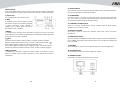
8.COMP CONTROL
Adjust the amount of compression applied to the channel. Turn the knob to the right to
increase the compression ration and the output gain will automatically adjusted. The result
is smoother, more even dynamics because louder signals are attenuated which the overall
level is boosted.
9.EQUALIZER
Hi
This is the treble control. You can use it to get rid of high frequency noises or to boost the
sound of cymbals or the high harmonics of the human voice. The gain range goes from -
15dB to +15dB with a center frequency of 12kHz.
MID
This is the mid range control. It can affect most fundamental frequencies of all
musical instruments and human voice. An attentive use of this control will give you a
very wide panorama of sound effects. The range goes from -15dB to +15 dB and the
center frequency of 2.5kHz.
LOW
This is bass control. it is used to boost male voice, kickdrum or bass guitar. the gain range
goes from -15dB to +15dB with a center frequency of 80Hz.
10.DFX (AUX) / POST
These controls are used to adjust the level of the POST FADER signal sent to
DFX (AUX) SENDS output, which can be used for monitor application and
effects & sound processors input.
11.PAN / BAL CONTROL.
The PAN control determines the stereo positioning of the channel signal
on the stereo L and R buses. The BAL control knob sets the balance
between left and right channels. Signal input through the stereo L/R bus.
12.PEAK LED
The peak level of the post-EQ signal is detected, and the PEAK Indicator
lights red when the level reaches 3 dB below clipping. For XLR-equipped
stereo input channels, both the post-EQ and post-mic-amp peak levels are
detected, and the indicator lights red if either of these levels reaches 3 dB
below clipping.
6 15

13.
LEVEL
This fader will adjust the overall level of
this channel and set the amount of
signal sent to the main output.
14.
MAIN MIX LEVEL
This fader is used to set the amount of
signal sent to the main mix output and
tape out.
15.
PHONES/ CONTROL ROOM
This fader sets the amount of signal sent
to the control room output and phones.
16.
DFX TO MAIN MIX
This fader is used to adjust the level of
the processed signal from DSP to MAIN
MIX BUS.
17.
2-TRACK SIGNAL PATH
If you push down the 2 TRACK SIGNAL
PATH knob, the 2 TRACK IN signal will
be routed into the CONTROL ROOM
output. Then push the knob again, the
2TRACK IN signal will be routed into the
MAIN MIX output.
18.
2-TK IN / MP3
This control is used to adjust the volume from -
∞
to +10dB.
19.
OUTPUT LEVEL
This stereo 8 segments LED meter will be indicate the level of overall output signal.
20.
ST RETURNS
This control is used to adjust the signal from ST RETURNS.
21.
DFX MUTE CONTROL
This control is used to activate /deactivate the effect facility. Sometimes , you can
also use the DFX FOOT switch for convenient operation.
INSTALLATION AND CONNECTION
Ok, you have got to this point and you are now in the position to successfully
operate your F82CX. However, we advise you to read carefully the following
section to be the real master of your own mixer. Not paying enough attention to
the input signal level, to the routing of the signal and the assignment of the
signal will result in unwanted distortion, a corrupted signal or no sound at all. So
you should follow these procedures for every single channel:
Before connecting mics or instruments, make sure that the power of all
your systems components including the mixer is turned off. Also, make sure
that all input and output controls of your mixer are turned down. This will avoid
damage to your speakers and avoid excessive noise.
Properly connect all external devices such as mics, power amplifiers,
speakers, effect processor etc.
Now, turn on the power of any peripheral devices, then power up the mixer.
Note: the power amplifier or powered monitors shall be turned on after the
mixer and turned off before the mixer.
Set the output level of your mixer or the connected power amplifier at no more
than 75%. Set the CONTROL ROOM/PHONE level at no more than 50%.
Position HI, MID and LOW EQ controls on middle position. Position panoramic
(PAN/BAL) control on center position.
While speaking into the mic (or playing the instrument ), adjust the channel
Level control so that the PEAK LED will blink occasionally, in this way you will
maintain good headroom and idea dynamic range.
You can shape the tone of each channel by adjusting the equalizer controls as
desired.
Now repeat the same sequence for all input channels. The main LED could
move up into the red section, in this case yo can adjust the overall output level
through the MAIN MIX control.
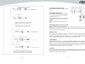
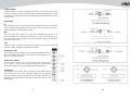
Some Final Tips on Wiring Configuration
You can connect unbalanced equipment to balanced inputs and outputs.
Simply follow these schematics.
14 7

22. PEAK/ MUTE LED
This LED lights up when the input signal is too strong. In case of the digital effect
module being muted, this LED also lights up.
23. PROGRAM (PUSH)
Adjust this knob to select the right effect you wish to perform. There are totally 100
options for you: Echo, Vocal, Plate and ver satile two-effect combination. When you
are satisfied the right preset, please push this knob to store this preset you want.
24. DIGITAL EFFECTS
It displays the selected preset.
25. PHANTOM LED
This LED indicates when the phantom power is switched on.
26. ON/OFF
This button will apply +48V phantom power only to the 4XLR inputs sockets. When
these XLR sockets are connected with devices that do not require phantom power,
please make sure the phantom power is turned off. Otherwise, this may damage the
device and mixer.
27. PWR LED
This LED indicates when the power is on in
your mixer.
28. 2TK IN /OUT TAPE IN
Use the Tape input if you wish to listen to your
Mix from a Taper Recorder or DAT. You can
assign the signal coming from the Tape
Recorder either to a pair of studio monitor
using the control room assignment on the front
panel or you can also send the signal directly
to the Main Mix.
TAPE OUT
These RCA jacks will route the main mix into a
tape recorder.
f
-REC
In power on state, press this key, it will go to the recording preparation state. Press
REC again to start recording. Any other operations are not available in recording
state until press POWER to stop recording.
g-POWER
When the unit is off, press this key and hold for about 2 or 3 seconds to turn on the
power supply of player. Repeat the above operation, you can turn off the power
supply of the player.
h-DISPLAY:
All the USB player information are monitored through this sexy & magic display.
8 13

MP3 Rec/Player
Il file system della memoria USB per i lettori USB è FAT16 e FAT32 e questi lettori
possono decodificare solo MP3. Possono esserci al massimo 7 cartelle subordinate.
a- PORTA USB
Per il collegamento di una memoria USB.
b-
7
77
7
PRE
In modalità Pausa, premete questo pulsante
per passare alla traccia precedente rimanendo
in pausa. Premendo questo pulsante in
modalità Play il lettore passa alla traccia
precedente e inizia a riprodurla.
c-
8
88
8
NEXT
In modalità Pausa, premete questo pulsante per passare alla traccia successiva
rimanendo in pausa. Premendo questo pulsante in modalità Play il lettore passa alla
traccia successiva e inizia a riprodurla.
d-
*
**
*
RPT
Premendo questo pulsante il lettore cambia in una delle seguenti 4 modalità:
REP ALL significa ripetere tutte le tracce in memoria; sullo schermo appare
REP1 significa ripetere una traccia; sullo schermo appare
Play in order significa riprodurre le tracce seguendo l’ordine; lo schermo è bianco.
Random play significa riprodurre le tracce in modo casuale; sul display appare A.
e-
12
1212
12
PLAY/PAUSE
In modalità Play, premete il pulsante
12
PLAY/ PAUSE per mettere in pausa il
lettore. In modalità Pausa, premete il pulsante
12
PLAY/ PAUSE per riavviare la
riproduzione.
29.
FOOT
SWITCH
This socket is used to connect external foots witch for your convenient operation,
it has the same function as DFX MUTE button.
30.
ST
RETURNS
Use these stereo 1 / 4" sockets to return the sound of an effect unit to the main
mix. You can also use them as extra auxiliary inputs, but they are primarily used
to connect the output of external effect processors.
31.
CONTROL
ROOM OUTPUT
These 1 / 4" phone sockets will be used to send the signal to studio monitor
speakers or to a second set of PA.
32.
DFX(AUX)
SENDS
This jack is used to output the channels signal that comes from DFX
(AUX)buses.
33.
MAIN
MIX OUTPUT
The stereo output is supplied 1/4" TRS sockets, which are used to send the audio
to an amplifier. Through the main mix level control, you can adjust the output level
from -
∞ to
10dB.
34.
PHONES
This socket will be used to send out the mix signal to a pair of headphones.
35. AC ADAPTER IN
This connector is used to connect the supplied AC adapter.
36. POWER ON /OFF
This button is used to turn the Main Power on and off.
12 9

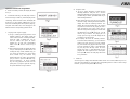
Operation Instruction for Song Module
a-
When no USB key inserted, the display will show
as Fig. 1
b-
Inserted the USB key, the USB player starts to
search the songs in USB key, and the display shows
"Searching". At the end of the search, the display will
show as Fig. 2. Using
7
PRE /
8
NEXT keys, you can
select one of following three menu options ("Playing",
"Program" and "Folder List"). Press Playing, the unit
will enter into the corresponding operation mode.
c-
"Playing" mode -single song play.
1).
In Fig 2, selecting the Playing mode to recall
following interface. This display shows the
name of all the folders containing MP3 files.
Using the
7
PRE /
8
NEXT keys, you can
scan the folders, then press
12
PLAY/
PAUSE key, you will open corresponding
folders. Press
STOP to return to Fig 2
interface.
2).
After opening the folder, the display will show
as Fig 3. This display shows MP3 file list, and
scrolling list using
7
PRE /
8
NEXT keys you
can choose the desired song. Press the
12
PLAY/ PAUSE key, the selected song
playback will start. In order to stop playback,
you just need to press the
STOP key.
Then, if you press the
12
PLAY/ PAUSE
key, the song playback will start from the
pause point, if you press again the stop key,
the system will return to Fig 3 interface.
d-
"Program" mode.
1).
In Fig 2, select "Program" to enter into the
following interface: "Play list Set ": Set the
playing list."Playing List": Play list. Press 7
PRE
/
8
NEXT
key to select, press STOP key to
return the Fig2 interface.
2).
After entering into the "Play List Set", the display
will show as Fig3. Selecting the desired folder, the
display will show the following interface. The
display will show all the MP3 files, the selected
song will be inserted into the playing list and a
mark will appear. Press again you're going to
delete the song from the playing list, and the mark
will disappear. Press the
STOP key, you will
return to Fig 2 interface. The playing list can
accept up to 20 songs, and it will display the list
according to song insert order.
3).
The display will show the following interface.
Press the
7
PRE /
8
NEXT key, you can select the
starting song, then press the
12
PLAY/ PAUSE
key, the selected song playback will start. Press
12
PLAY/ PAUSE key again, or press
STOP
key, the play back will stop. Press
12
PLAY/
PAUSE key again, or press
STOP key, the
playback will start again from the same point.
Twice press
STOP, the USB player will return
to Fig 3 interface.
e-
Folder List:
See the Fig 3, the display shows MP3 files folders names. Use
7
PRE /
8
NEXT key to scan,
press
12
PLAY/ PAUSE key, you'll enter into corresponding folder. In order to return to Fig5
interface, you just need to press the
STOP key.
10 11
-
 1
1
-
 2
2
-
 3
3
-
 4
4
-
 5
5
-
 6
6
-
 7
7
-
 8
8
-
 9
9
-
 10
10
-
 11
11
-
 12
12


Fiveo F82CX Manuale del proprietario
- Categoria
- Controller DJ
- Tipo
- Manuale del proprietario
in altre lingue
- English: Fiveo F82CX Owner's manual
Altri documenti
-
LD Systems VIBZ 8 DC Manuale del proprietario
-
LD Systems VIBZ 6D Manuale utente
-
 Alto Professional TMX160DFX Guida Rapida
-
LD Systems LDVIBZ24DC Manuale del proprietario
-
-
Alto zmx244fx Guida Rapida
-
-
-
Fender SR8500 Manuale utente
-
Yamaha MGP32X Manuale utente
