
Bedienungsanleitung
Operation Manual
Innovation,
die bewegt!
2624, 2625
H0 Niederbordwagen mit Betonmischer
H0 Low side car with cement mixer
RAIL
motion
AC
~
DC
=
DCC
MM
NEM
2L 3L
1. Wichtige Hinweise / Important information ........................................................ 2
2. Einleitung / Introduction ..................................................................................... 3
3. Betrieb / Operation ............................................................................................ 3
4. Wartung / Maintenance ..................................................................................... 7
5. Fehlersuche / Trouble-shooting ......................................................................... 7
6. Gewährleistung / Warranty ................................................................................ 8
7. Technische Daten / Technical data .................................................................... 8

2
DE EN
1. Wichtige Hinweise
Bitte lesen Sie vor der ersten Anwendung des
Produktes bzw. dessen Einbau diese Bedienungs-
anleitung aufmerksam durch. Bewahren Sie diese
auf, sie ist Teil des Produktes.
1.1 Sicherheitshinweise
Vorsicht:
Verletzungsgefahr!
Aufgrund der detaillierten Abbildung des Originals
kann das Produkt Spitzen, Kanten und abbruch-
gefährdete Teile aufweisen. Für die Montage sind
Werkzeuge nötig.
Stromschlaggefahr!
Das Modell enthält eine elektronische bzw. me-
chanische Baugruppe. Es ist nicht vorgesehen,
dass das Modell vom Kunden geöffnet wird. Es
darf nicht beschädigt oder Feuchtigkeit ausge-
setzt werden. Die genannten Baugruppen sind für
den einwandfreien Betrieb erforderlich.
Bei Aufgleisen des Dreileitermodells muss die
Gleisspannung abgeschaltet sein.
Beschädigte Mittelschleifer können zu Störungen
und Kurzschlüssen führen. Tauschen Sie daher
beschädigte Mittelschleifer aus. Ersatzmittel-
schleifer nden Sie im Viessmann-Programm,
Art. 2255.
Betreiben Sie das Modell niemals unbeaufsich-
tigt.
Bruchgefahr!
Modell stets vorsichtig am Gehäuse anfassen, da
die ligranen Teile des Modells sonst abbrechen
könnten.
1.2 Das Produkt richtig verwenden
Dieses Produkt ist bestimmt:
- Zum Betrieb auf Modelleisenbahnanlagen oder
Dioramen.
- Zum Betrieb mit einem zugelassenen Modell-
bahntransformator mit einer Ausgangsspannung
von max. 24 V bzw. an einer Digitalzentrale der
Formate DCC und/oder Märklin Motorola (MM)
wie z. B. dem Viessmann Commander, Art. 5300
bzw. 5320.
- Zum Betrieb in trockenen Räumen.
Jeder darüber hinausgehende Gebrauch gilt als
nicht bestimmungsgemäß. Für daraus resultierende
Schäden haftet der Hersteller nicht.
1. Important information
Please read this manual completely and attentively
before using the product for the rst time. Keep this
manual. It is part of the product.
1.1 Safety instructions
Caution:
Risk of injury!
Due to the detailed reproduction of the original,
this product can have peaks, edges and break-
able parts. Tools are required for installation.
Electrical hazard!
The model contains an electronic respectively
mechanical subassembly. It should not be opened
by the customer. It should not be damaged or ex-
posed to humidity. The subassemblies mentioned
above are essential for trouble-free operation.
When placing the 3-rail version model onto the
tracks, the track voltage has to be switched off.
Damaged pickup shoes might cause short circuits
and malfunctions, so please replace damaged
pickup shoes. You can nd replacements in the
Viessmann assortment, item 2255.
Never leave the model unattended during opera-
tion.
Risk of breakage!
Always handle this model carefully since the
many nely detailed parts may otherwise be
damaged.
1.2 Using the product for its correct purpose
This product is intended:
- For operation on model train layouts and diora-
mas.
- For connection to an authorized model train
transformer with an output voltage of max. 24 V
or a digital command station with DCC/MM, e. g.
Viessmann Commander, items 5300 resp. 5320.
- For operation in dry rooms only.
Using the product for any other purpose is not ap-
proved and is considered incorrect. The manufac-
turer is not responsible for any damage resulting
from the improper use of this product.

3
1.3 Packungsinhalt überprüfen
Kontrollieren Sie den Lieferumfang auf Vollstän-
digkeit:
- Niederbordwagen mit Betonmischer
- Anleitung
2. Einleitung
Die Funktionsmodelle der Serie RailMotion sorgen
für Leben auf der Modelleisenbahn. Das speziell ent-
wickelte Funktionsmodell ist mit einer elektronischen
Steuerung ausgerüstet, die realistische Bewegungs
-
effekte erzeugt. Hier handelt es sich um ein Arbeits-
fahrzeug für den Gleisbau, z. B. zum Gießen von
Signal- und Oberleitungsfundamenten. Das Modell
hat eine elektrisch angetriebene Mischtrommel, die
sich in beide Richtungen drehen kann.
2.1 Digitaldecoder integriert
Dieses Funktionsmodell ist mit einem integrierten
Digitaldecoder ausgestattet. Die Steuerung ist mit
dem Viessmann Commander, Art. 5300 bzw. 5320
oder mit jeder anderen handelsüblichen Digitalzen-
trale der Formate DCC oder Märklin-Motorola mög
-
lich. Die Funktion der Trommel ist im Digitalbetrieb
schaltbar.
2.2 Analogbetrieb
Die Grundfunktion ist auch im DC- und AC-Betrieb
vorhanden.
3. Betrieb
3.1 Digitalbetrieb (DCC/MM)
Im Digitalbetrieb sind die Funktionen Stop, Mischbe-
trieb und Ausleeren verfügbar und über Funktions-
tasten steuerbar (vgl. Abschnitt Funktionstastenbe-
legung). Der Betonmischer ist wie eine DCC- oder
Märklin-Motorola Lokomotive programmierbar und
steuerbar.
Als Grundeinstellung startet bzw. stoppt die Funk-
tions-taste:
F1 - den Betonmischer in der normalen Betriebs-
richtung (Drehung im Uhrzeigersinn von hinten auf
die Trommelöffnung gesehen).
F2 - startet bzw. stoppt die Ausleerungsfunktion (Be-
tonmischer läuft mit ca. doppelter Geschwindigkeit
in Gegenrichtung).
3.2 Programmierung im DCC-Modus
Der Decoder im Wagen lässt sich im DCC-Format
auf dem Programmiergleis und mittels POM pro-
grammieren.
1.3 Checking the package contents
Check the contents of the package for complete-
ness:
- Low side car with cement mixer
- Manual
2. Introduction
The functional models of the RailMotion series
bring life to your model train layout. This specially
developed functional model is equipped with an
electronic control generating realistic movement.
This particular model is a maintenance vehicle for
maintenance work along the line, e. g. for pouring
concrete foundations for signal or catenary masts.
The model has an electrically powered cement
mixer drum that can turn in both directions.
2.1 Integral digital decoder
This functional model is equipped with a digital de-
coder, which can be controlled with the Viessmann
Commander, items 5300 resp. 5320 and any com-
mercially available command station generating
either the DCC or the Märklin Motorola data format.
The mixer drum can be switched in digital mode.
2.2 Analogue operation
The basic function is also available in AC and DC
mode.
3. Operation
3.1 Digital mode (DCC/MM)
The functions “Stop”, “Mixing” and “Pouring” are
available and can be triggered with function buttons
(also refer to the chapter about the assignment of
function buttons). This vehicle can be programmed
and operated like a DCC or MM locomotive. The
default settings are as follows:
F1 – starts and stops the movement of the drum
in the normal rotating direction (turning clockwise
when viewed from behind towards the opening of
the drum).
F2 – starts and stops the “Pouring” function (drum turns
in the opposite direction at about twice the speed).
3.2 Programming in DCC
In DCC the decoder in the vehicle can be pro-
grammed on the programming track and on the
main (POM).

4
3.3 Programmierung mit Märklin-
Motorola-Zentralen
Vorsicht:
Wenn Sie eine Multiprotokoll-Zentrale einsetzen
(DCC- und Motorola-Format), empfehlen wir, den
Decoder im DCC-Format zu programmieren. Sie
können den Decoder nach dem Programmieren
auch im Motorola-Format ansteuern.
Die Motorola-Programmierung ist entsprechend den
üblichen Verfahren realisiert. Die Signalisierung der
Zustände erfolgt durch längere oder kürzere Se-
quenzen aus abwechselndem Drehen und Anhalten
der Trommel.
Stellen Sie den Wagen auf ein Gleis, das mit dem
Gleisausgang der Zentrale verbunden ist. Es darf
kein weiteres Fahrzeug auf dem Gleis stehen, da
der darin bendliche Decoder sonst ggf. ebenfalls
programmiert wird.
Führen Sie für die Programmierung mittels Märklin-
Motorola-Zentralen zunächst einen Reset an der
Zentrale durch (mittels gleichzeitigen längeren Drü-
ckens der Tasten „Stop“ und „Go“) oder schalten Sie
die Zentrale kurz aus und wieder ein.
Wählen Sie zunächst die aktuelle Adresse des
Decoders oder die Adresse 80 (wenn Sie z. B. die
aktuelle Adresse des Decoders nicht kennen). Bei
der Auslieferung hat der Decoder die Adresse 3.
Schalten Sie alle Funktionen (F1 bis F4) aus.
Drücken Sie als nächstes die „Stop“-Taste der Zentra-
le. Betätigen Sie dann den Richtungsumschalter und
halten Sie ihn gedrückt. Drücken Sie kurz die Taste
„Go“. Sobald die Trommel des Fahrzeugs beginnt, sich
abwechselnd zu drehen und zu stoppen (nach ca. 2
Sekunden), bendet sich der Decoder im Program-
miermodus und Sie können den Umschalter loslassen.
Im Programmiermodus können Sie die Register des
Decoders wie folgt programmieren:
1. Wählen Sie ein Register zum Programmieren
aus, indem Sie die Nummer des Registers als
Motorola-Lok-adresse an Ihrer Zentrale einge-
ben. Beachten Sie, dass bei manchen Zentralen
eine führende 0 eingegeben werden muss.
2. Betätigen Sie den Richtungsumschalter. Der
Rhythmus von Drehen und Stoppen der Trommel
wird schneller.
3. Geben Sie den gewünschten Wert des Registers
ein, indem Sie den Wert als Motorola-Lokadresse
an Ihrer Zentrale eingeben. Die Motorola Loko-
motivadresse 80 entspricht dem Wert 0.
4. Betätigen Sie den Richtungsumschalter erneut.
Der Rhythmus von Drehen und Stoppen der
Trommel wird wieder langsamer.
3.3 Programming with Märklin Motorola
central units
Caution:
If you use a multi protocol command station
generating DCC and Motorola signals we recom-
mend to programme the decoder in DCC mode.
Of course, after programming you may control the
vehicle also in the Motorola format.
Programming in the Motorola mode can be done
with the commonly known methods. The status is
indicated by longer or shorter sequences of rotat-
ing and stopping the drum.
Place the vehicle on the tracks connected to the
track output of the central unit. In order to prevent
any other vehicle from being inadvertently pro-
grammed there must be no other vehicle on the
same track.
When programming with a Märklin Motorola central
unit rst make a reset by simultaneously pressing
the “Stop” and the “Go” button for a longer period.
Alternately, you may switch off the central unit for a
moment and then turn it back on again.
Then select the current address of the decoder or
the address 80 (in case you do not know decoder
address). The default address is 3. Turn off all
functions (F1 through F4).
Then push the “Stop” button of the central unit followed
by the change-of-direction button, which you keep
pressed down. Press the “Go” button for a short
moment. As soon as the drum starts rotating (after
about two seconds) the decoder has shifted into
the programming mode. Now you may release the
change-of-direction button.
While in programming mode you may programme
the registers of the decoder as follows:
1. Select a register you want to programme by en-
tering the number of the register as a Motorola
locomotive address on your central unit. Please
bear in mind that some central units require the
prex 0 when entering the address.
2. Activate the change-of-direction button. The
rhythm of the drum rotating and stopping be-
comes faster.
3. Enter the desired value for the register by enter-
ing the value as a Motorola locomotive address
on your command station. The Motorola locomo-
tive address 80 means a value of 0.
4. Press the change-of-direction button once again.
The rhythm of the drum rotating and stopping
slows down again.

5
Wiederholen Sie die Punkte 1 bis 4 für alle Register,
die Sie programmieren wollen. Um ein Register zum
Programmieren auszuwählen oder einen Wert für ein
Register einzugeben, müssen Sie die eingegebene
Zahl immer wie beim Auswählen einer Lokadresse
an Ihrer Zentrale bestätigen. Der Rhythmus der
Bewegung zeigt an, welche Eingabe der Decoder
erwartet:
- Langsamer Rhythmus: Eingabe einer Register-
nummer.
- Schneller Rhythmus: Eingabe des Wertes eines
Registers. Zum Beenden des Programmiermo-
dus drücken Sie auf „Stop“.
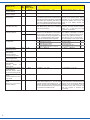
3.4 CV-Tabelle
Der integrierte Decoder erlaubt eine Reihe von
Einstellungen, um den Umgang mit diesem Funk-
tionsmodell besonders komfortabel zu gestalten.
Insbesondere lassen sich die Funktionstasten, die
die Betriebsart der Trommel steuern, frei belegen.
Die folgende Tabelle gibt Aufschluss über die Kon-
gura-tionsmöglichkeiten. Die Werkseinstellungen
sind jeweils in Klammern angegeben.
Tipp:
Es gibt zwei CVs für die Funktionstastenzuordnung,
nämlich CV 58 und CV 59.
Der Decoder „hört“ für das Aktivieren der Mischfunk-
tion auf beide CVs.
Damit können z. B. mehrere Waggons auf derselben
Digitaladresse über die in CV 58 hinterlegte Funkti-
on gleichzeitig ein- und ausgeschaltet werden. Mit
der in CV 59 hinterlegten Funktonstaste kann dann
die individuelle Steuerung jedes Wagens verwirk-
licht werden.
3.5 Analogbetrieb
Achtung:
Verwenden Sie für den Analogbetrieb ausschließ-
lich regelbare Modelleisenbahntrafos. Der Betrieb
mit Analog-Fahrreglern mit Pulsweitenansteue-
rung ist nicht möglich und kann zu Fehlfunktionen
führen.
Im Analogbetrieb dreht sich die Trommel bei ausrei-
chender Gleisspannung im Mischbetrieb während
der Fahrt.
Die Kongurationsvariablen, die im Digitalbetrieb
eingestellt sind (z. B. Drehrichtung, Geschwindig-
keit), sind auch im Analogbetrieb aktiv.
Repeat steps 1 through 4 for all registers you wish
to programme. In order to select a register for pro-
gramming or to enter a value into a register you
must always conrm the number entered in the
same way as if you enter a locomotive address.
The rhythm of movement indicates which type of
data entry is expected by the decoder:
- Slow rhythm: Entry of a register number.
- Faster rhythm: Entry of a register value. Press
the “Stop” button for exiting the programming
mode.
3.4 CV table
The integral decoder supports a number of adjust-
ments for easy and comfortable handling of this
functional model. Particularly, the function buttons
controlling the drum may be freely assigned.
The following table shows the possible congura-
tion options. Default values are given in brackets.
Hint:
There are two CVs for assigning function buttons,
namely CV 58 and CV 59.
The decoder “listens” to both CVs for activating the
concrete mixing function.
This enables e.g. several coaches at the same
digital address to be switched on and off simul-
taneaously via the function set in CV 58. With
the function button assigned to CV 59 you may
realize the individual control of each vehicle.
3.5 Analogue operation
Please note:
Only use model train transformers providing
standard speed control by voltage control in
analogue mode. Do not use controllers employing
pulse width modulation. This may lead to faults
and irregular operation.
In analogue mode the drum rotates in concrete
mixing mode when the vehicle is moving (drawn
by a locomotive) if there is sufcient track voltage
available.
The conguration variables adjusted in digital mode
(e. g. rotation clockwise or anti-clockwise) are also
active in analogue mode.

6
Name der CV
Name of CV
CV-
Nr.
No.
Eingabewerte
(Default)
value range
Erläuterungen/Hinweise Remarks
Basisadresse
Primary address
1 1 … 255 (3) Wertebereich bei DCC: 1 … 127 Range of values in DCC: 1 ... 127
Versionsnummer
Version number
7 Nur lesbar! Read only!
Hersteller
Manufacturer
8(109) Schreiben Sie den Wert 8 um alle Werte auf
den Auslieferungszustand zuzückzusetzen.
Wenn Sie den Wert 9 schreiben, werden alle
Werte außer der Lokadresse und außer CV
29 auf den Auslieferungszustand zurückge-
setzt. CV 8 ändert seinen Wert hierbei nicht.
Writing the value 8 in CV 8 resets the
decoder to the default values. Writing
the value 9 in CV 8 resets all values
except the address and CV 29. The
value of CV 8 always remains the
same.
Zwangsbremsung
Automatic train stop
11 0 … 255 (100) Automatischer Halt bei Ausfall des Digitalsi-
gnals. Berechnung: Wert x 0,1 = Zeit (sec)
bis zur Stop-Auslösung.
Automatic stop in case of signal in-
terruption from the command station:
Value x 0.1 = time [sec] until stop
command is executed.
Erweiterte Adresse
Extended address
17 192 … 255 (0) Erlaubt Adresse über 127 wenn die lange
Adresse in CV 29 aktiviert ist, nur für DCC.
Bei den meisten Zentralen ist es möglich,
erweiterte Adressen direkt einzugeben. Die
CVs 17, 18 und 29 werden dann von der
Zentrale automatisch richtig eingestellt.
Allows addresses above 127 if the
long address is activated in CV 29, in
DCC. Most command stations permit
entering long addresses directly. In
this case the CVs 17, 18 and 29 are
set automatically to the proper values.
18 0 … 255 (0)
Konguration
Conguration
29 (30) Bit
0
5
Drehrichtung normal
Drehrichtung invertiert
Kurze Adresse in CV 1
Lange Adresse in CV 17 + CV 18
Normal rotation
Inverted rotation
Short address in CV 1
Long address in CV 17 + CV 18
Wert
0
1
0
32
Vorzusgprotokoll
Preferred protocol
48 0, 1 (0) 0 = DCC; 1 = Motorola 0 = DCC; 1 = Motorola
Geschwindigkeit im
Mischbetrieb
Rotation speed in
concrete mixing mode
54 0 ... 80 (21)
Geschwindigkeit im
Entleerungsbetrieb
Revs in “Pouring” mode
55 0 ... 80 (40)
Funktionstaste für
Mischbetrieb
Function button for
mixing mode
58 0 ... 28 (1) 0 = inaktiv; 1 = F1; usw. 0 = not active; 1 = F1; etc.
Alternative Funktionstaste
für Mischbetrieb
Alternate function button
for concrete mixing mode
59 0 ... 28 (0) 0 = inaktiv; 1 = F1; usw. 0 = not active; 1 = F1; etc.
Funktionstaste für Aus-
leeren
Function button for “Pou-
ring” mode
60 0 ... 28 (2) 0 = inaktiv; 1 = F1; usw. 0 = not active; 1 = F1; etc.
Motorola Funktions-ad-
resse
Motorola secondary
function address
61 0 ... 255 (0)
Durch Eingabe einer beliebigen Adresse
werden die Funktionen F1 - F4 für diese
Motorola-Adresse als Funktionen F5 - F8
gewertet. So kann man 8 Funktionen aufru-
fen, auch mit Zentralen die nur 4 Funk-tionen
pro Lokomotive schalten können.
By entering any address the functions
F1 through F4 are considered to be F5
through F8 for this particular Motorola
address. Thus it is possible to call up
8 functions even with a central unit
that only supports 4 functions per
locomotive.

7
7
4. Wartung
Damit Sie lange ungetrübte Freude an Ihrem
Schienenfahrzeugmodell haben, ist eine regelmä-
ßige Wartung unerlässlich. Bitte beachten Sie die
folgenden Hinweise und führen Sie regelmäßig die
Wartungsschritte durch.
Achtung:
Vollständige Wartung des Fahrzeugs alle 25
Betriebsstunden.
4.1 Laufwerke (Achsen):
Schmieren Sie die Achsen mit einem winzigen
Tropfen sehr dünnüssigen synthetischen Öl.
4.2 Radschleifer:
Der Wagen nimmt ggf. über mehrere Räder Strom
auf, erkennbar an den Schleifern auf der Innenseite
der Räder. Bringen Sie daher eine winzige Menge
Schmierfett auf die Innenseiten der Räder auf.
5. Fehlersuche und Abhilfe
Jedes Viessmann-Produkt wird unter hohen Quali-
tätsstandards gefertigt und vor Auslieferung geprüft.
Sollte es dennoch zu einer Störung kommen, prüfen
Sie bitte als erstes die Stromzufuhr (verschmutzte
Gleise, Betriebsspannung am Gleis). Kontrollieren
Sie ggf. auch, ob die CV-Einstellungen zu Ihrem
Betriebsmodus passen, z. B. ist bei Wechsel des
Datenprotokolls oder der Zentrale auch im Decoder
der Wechsel erlaubt (CV 48 und 49)? Löst eine
Rückstellung auf Werkseinstellung vielleicht das
Problem (CV 8)?
Falls der Antrieb aus irgendwelchem Grund blockiert
sein sollte, wird der Motor aus Sicherheitsgründen
ausgeschaltet. Der Decoder versucht dann alle 5
Sekunden, den Motor erneut zu starten.
Wenn Sie die Fehlerursache nicht finden und
beheben können, lesen Sie bitte das Kapitel 6
„Gewährleistung“.
4. Maintenance
Regular maintenance provides you with much
enjoyment with your rail vehicle model for many
years. Please observe the following remarks and
carry out the maintenance work as described regu-
larly.
Attention:
Full maintenance is required after every 25 hours
of operation.
4.1 Running gear (axles):
Lubricate the axles with a tiny drop of thin uid
synthetic oil.
4.2 Wheel wipers:
The vehicle may pick up current via several wheels,
which can be detected by the wheel wipers on the
inside of the wheels. Apply a tiny amount of grease
to the inside of the wheels.
5. Trouble-shooting
All Viessmann products are produced with high
quality standards and are checked before deliv-
ery. Should a fault occur despite these measures
please rst check the power supply (dirty tracks,
operating voltage). Also check if the CV settings
are suitable for operation, for instance, is changing
from one data format to the other enabled in the
decoder (CV 48 and 49). Can you resolve the issue
by resetting to default values (CV 8)?
Should the drive mechanism be blocked for any
reason the motor will be automatically switched
off to avoid damage. The decoder will attempt to
restart the movement every 5 seconds.
Please refer to chapter 6 “Warranty” if you cannot
nd the cause of the failure and therefore cannot
rectify it.

Modellbauartikel, kein Spielzeug! Nicht geeignet für
Kinder unter 14 Jahren! Anleitung aufbewahren!
Model building item, not a toy! Not suitable for children
under the age of 14 years! Keep these instructions!
Ce n’est pas un jouet! Ne convient pas aux enfants de moi-
ns de 14 ans! Conservez cette notice d’instructions!
Não é um brinquedo! Não aconselhável para menores de
14 anos! Conservar o manual de instruções!
Modelbouwartikel, geen speelgoed! Niet geschikt voor
kinderen onder 14 jaar! Gebruiksaanwijzing bewaren!
Articolo di modellismo, non è un giocattolo! Non adatto
a bambini al di sotto dei 14 anni! Conservare istruzioni per
l’uso!
Artículo para modelismo ¡No es un juguete! No
recomendado para menores de 14 años! Conserva las
instrucciones de servicio!
DE
EN
FR
NL
IT
ES
PT
Made in Europe
Viessmann
Modelltec
hnik GmbH
Bahnhofstraße 2a
D - 35116 Hatzfeld-Reddighausen
+49 6452 9340-0
www.viessmann-modell.de
8
87573
Stand 05/sw
03/2022
Ho/Kf
6. Gewährleistung
Jeder Artikel wurde vor Auslieferung auf volle
Funktionalität geprüft. Der Gewährleistungszeitraum
beträgt 2 Jahre ab Kaufdatum. Tritt in dieser Zeit ein
Fehler auf und Sie nden die Fehlerursache nicht,
nehmen Sie bitte Kontakt mit uns auf (service@
viessmann-modell.com). Senden Sie uns den Artikel
zur Kontrolle bzw. Reparatur bitte erst nach Rück-
sprache zu. Wird nach Überprüfung des Artikels ein
Herstell- oder Materialfehler festgestellt, wird er kos-
tenlos instandgesetzt oder ausgetauscht. Von der
Gewährleistung und Haftung ausgeschlossen sind
Beschädigungen des Artikels sowie Folgeschäden,
die durch unsachgemäße Behandlung, Nichtbeach-
ten der Bedienungsanleitung, nicht bestimmungsge-
mäßen Gebrauch, eigenmächtigen Eingriff, bauliche
Veränderungen, Gewalteinwirkung, Überhitzung u.
ä. verursacht werden.
7. Technische Daten
Systeme: analog, DCC, MM
RailCom: nicht vorhanden
Betriebsspannung:
0 – 21 V analog / bis 24 V digital
Betriebsstrom: < 100 mA
Ruhestrom: < 30 mA
Temperatur / rel. Feuchtigkeit (Betrieb):
+8 – +35 °C / max. 85 % nicht betauend.
Temperatur / rel. Feuchtigkeit (Lagerung):
0 – 40 °C / max. 85 % nicht betauend.
Kupplungsschacht gemäß NEM 362
Kupplungsattrappen und mitgelieferte System-
kupplung
Metallräder
LüP: 15,8 cm
Gewicht: 95 g
6. Warranty
Each model is tested as to its full functionality prior
to delivery. The warranty period is 2 years starting
on the date of purchase. Should a fault occur during
this period please contact our service department
([email protected]). Please send
the item to the Viessmann service department for
check and repair only after consultation. If we nd
a material or production fault to be the cause of the
failure the item will be repaired free of charge or
replaced. Expressively excluded from any warranty
claims and liability are damages of the item and
consequential damages due to inappropriate han-
dling, disregarding the instructions of this manual,
inappropriate use of the model, unauthorized dis-
assembling, construction modications and use of
force, overheating and similar.
7. Technical data
Systems: analogue, DCC, MM
RailCom: not supported
Operating voltage:
0 – 21 V analogue / up to 24 V digital
Operating current: < 100 mA
Standby current: < 30 mA
Temperature / relative humidity (operation):
+8 – +35 °C / max. 85 % non-condensing.
Temperature / relative humidity (storage):
0 – 40 °C / max. 85 % non-condensing.
NEM coupler shaft as per NEM 362
Imitations of prototype eye-and-hook couplers
as well as standard H0 couplers provided
Metal wheels
Length over buffers: 15.8 cm
Weight: 95 g
-
 1
1
-
 2
2
-
 3
3
-
 4
4
-
 5
5
-
 6
6
-
 7
7
-
 8
8


in altre lingue
- English: Viessmann 2625 Owner's manual
- Deutsch: Viessmann 2625 Bedienungsanleitung
Documenti correlati
-
Viessmann 2619 Manuale del proprietario
-
-
-
-
Viessmann 5224 Manuale del proprietario
-
-
-
-
-

