
Bedienungsanleitung
Operation Manual
Innovation,
die bewegt!
AC
~
DC
=
DCC MM
1. Wichtige Hinweise / Important information ....................................................... 2
2. Einleitung / Introduction.................................................................................... 2
3. Anschluss / Connection.................................................................................... 3
4. Konguration des Steuermoduls / Conguring the control module .................. 5
5. Programmierung des Steuermoduls / Programming the control module ......... 6
6. Der Viessmann-Signalbus / The Viessmann signal bus .................................. 7
7. Die Signal-Logik / The signal logic ................................................................... 8
8. Das Vorsignal / The distant signal .................................................................... 17
9. Ansteuerung im Digitalbetrieb / Digital operation ............................................. 18
10. Gewährleistung / Warranty ............................................................................... 20
11. Technische Daten / Technical data .................................................................. 20
Steuermodul für
Lichtsignale digital/analog
Control module for
colour light signals
digital/analogue
5224

2
DE EN
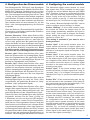
1. Wichtige Hinweise
Bitte lesen Sie vor der ersten Anwendung des
Produktes bzw. dessen Einbau diese Bedienungs-
anleitung aufmerksam durch. Bewahren Sie diese
auf, sie ist Teil des Produktes.
1.1 Sicherheitshinweise
Vorsicht:
Verletzungsgefahr!
Für die Montage sind Werkzeuge nötig.
Stromschlaggefahr!
Die Anschlussdrähte niemals in eine Steckdo-
se einführen! Verwendetes Versorgungsgerät
(Transformator, Netzteil) regelmäßig auf Schäden
überprüfen. Bei Schäden am Versorgungsgerät
dieses keinesfalls benutzen!
Alle Anschluss- und Montagearbeiten nur bei
abgeschalteter Betriebsspannung durchführen!
Ausschließlich nach VDE/EN gefertigte Modell-
bahntransformatoren verwenden!
Stromquellen unbedingt so absichern, dass es
bei einem Kurzschluss nicht zum Kabelbrand
kommen kann.
1.2 Das Produkt richtig verwenden
Dieses Produkt ist bestimmt:
- Zum Einbau in Modelleisenbahnanlagen und
Dioramen.
- Zum Anschluss an einen Modellbahntransformator
(z. B. Art. 5200) bzw. an eine Modellbahnsteue-
rung mit zugelassener Betriebsspannung.
- Zum Betrieb in trockenen Räumen.
Jeder darüber hinausgehende Gebrauch gilt als
nicht bestimmungsgemäß. Für daraus resultierende
Schäden haftet der Hersteller nicht.
1.3 Packungsinhalt überprüfen
Kontrollieren Sie den Lieferumfang auf Vollstän-
digkeit:
- Steuermodul für Lichtsignale
- 2 Schrauben
- 15 Stecker
- Anleitung
2. Einleitung
Das Viessmann Steuermodul für Lichtsignale
Art. 5224 steuert ein zwei- oder mehrbegriffiges
Tageslicht-Signal mit dem dazu gehörenden Vorsi-
gnal. Das Signal sollte mit LEDs bestückt sein. Ein
1. Important information
Please read this manual completely and attentively
before using the product for the first time. Keep this
manual. It is part of the product.
1.1 Safety instructions
Caution:
Risk of injury!
Tools are required for installation.
Electrical hazard!
Never put the connecting wires into a power
socket! Regularly examine the transformer for
damage. In case of any damage, do not use the
transformer.
Make sure that the power supply is switched
off when you mount the device and connect the
cables!
Only use VDE/EN tested special model train
transformers for the power supply!
The power sources must be protected to avoid
the risk of burning cables.
1.2 Using the product for its correct purpose
This product is intended:
- For installation in model train layouts and diora-
mas.
- For connection to an authorized model train
transformer (e. g. item 5200) or a digital com-
mand station.
- For operation in dry rooms only.
Using the product for any other purpose is not
approved and is considered inappropriate. The
manufacturer is not responsible for any damage
resulting from the improper use of this product.
1.3 Checking the package contents
Check the contents of the package for complete-
ness:
- Digital control module for colour light signals
- 2 screws
- 15 plugs
- Manual
2. Introduction
The Viessmann control module for colour light
signals item 5224 is designed for a two- or multi-
aspect colour light signal with the associated
distant signal. The signal should be equipped with

3
Signal mit wenigen Glühlämpchen kann ebenfalls
angeschlossen werden. Alle gleichzeitig leuchten-
den LEDs und Glühlämpchen dürfen zusammen
nicht mehr als 300 mA verbrauchen. Sonst schaltet
eine Überlasterkennung das Modul ab.
Die COM-Buchse muss immer mit einer Buchse
Strom (rt) verbunden werden und bedeutet den
gemeinsamen Rückleiter aller Schalteingänge.
Das Modul wird durch einen einfachen Einstellvor-
gang auf den Typ des angeschlossenen Signals
und ggf. auf das gewünschte Digitalsystem sowie
die Digitaladresse programmiert. Bei diesem Vor-
gang werden gleichzeitig die Eigenschaften des zu
steuernden Signals konfiguriert:
- Zwei- oder mehrbegriffiges Signal
- Gekoppeltes Signal
- Separates Vorsignal oder Vorsignal am Mast
- Bahnhofs- oder Blocksignal-Logik
- Bremsgenerator oder Bremsmodul ja / nein
Die einmal eingestellte Konfiguration und das ak-
tuelle Signalbild werden intern gespeichert und bei
jedem Spielbeginn wieder zurückgeholt.
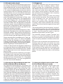
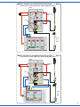
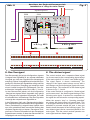
3. Anschluss
Das Steuermodul erhält seine Energie über die
Anschlussbuchsen „bn“ und „rt“ (siehe Abb. 1).
Bei konventionellem Betrieb verbinden Sie diese
Buchsen mit den beiden Ausgangsbuchsen Ihres
Licht- bzw. Schalttransformators (siehe Anleitung
des Trafos). Beim Digitalbetrieb verbinden Sie die
Buchsen „bn“ und „rt“ mit dem Gleisausgang der
Digitalzentrale oder eines Boosters. Bei Märklin-Mo-
torola beachten Sie bitte die Polarität (Abb. 1).
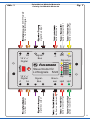
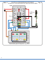
Das Lichtsignal (Haupt- und Vorsignal) schließen
Sie an die Vielfachbuchse auf der Oberseite des
Moduls an. Die Anschlussdrähte an der Schutz-
diode und den Widerständen des Signals kürzen
Sie dazu auf ca. 10 mm und stecken sie einfach
direkt (d. h. ohne Stecker) in die zugehörige Mi-
niatur-Buchse. Den Anschluss der verschiedenen
Signaltypen zeigen die Abbildungen 2 bis 5.
Im konventionellen Betrieb stellen Sie die Signa-
le mit Hilfe der Viessmann Tasten-Stellpulte Art.
5547 (für vier 2-begriffige Signale), 5546 (für zwei
3-begriffige Signale) und 5545 (für zwei 4-begrif-
fige Signale). So entsprechen Tastenfarbe und
-anordnung dem jeweiligen Signaltyp und dessen
Stellmöglichkeiten.
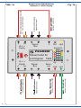
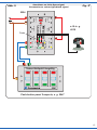
Setzen Sie mehrere Steuermodule für Lichtsignale
ein, dann können Sie diese über den Viessmann-Si-
gnalbus miteinander verbinden (siehe Abb. 6). Da-
bei ist unbedingt die Richtung des Signalbusses zu
beachten. Er überträgt Informationen von einem
Signal zum vorhergehenden, also entgegen der
LEDs. A signal with only a few incandescent lamps
may also be connected. All LEDs or lamps oper-
ated simultaneously must not draw more than 300
mA. Otherwise the overload safety cut-out will turn
off the module.
The COM socket should always be connected with
one of the power supply “rt” sockets. It is used as a
common coupling for all switching inputs.
The module is configured to suit the specific type of
signal and the desired digital system and address.
At the same time the characteristics of the signal
are configured:
- 2- or multi-aspect signal
- Signal with speed restriction
- Separate distant signal or distant signal on the
mast of the main signal
- Yard- or block signal logic
- Brake generator or brake module yes / no
The configuration and the type of signal are stored
in the module and retrieved whenever the signal
is operated.
3. Connection
The control module is powered via the sockets
“bn” and “rt” - both in analogue and digital mode
(see fig. 1). Connect these sockets with the output
terminals of your lighting transformer (analogue
mode) as specified in the manual provided with the
transformer. In digital mode connect the sockets
“bn” and “rt” with the track terminals of the digital
command station or the booster. Please observe
the correct polarity for Märklin Motorola (see fig.
1). Connect the colour light signal to the 12-pin
plug at the top of the module. The wires from the
protective diode and the resistors of the signal are
to be shortened to 10 mm. How to connect different
types of signals is shown in fig. 2 – fig. 5.
In analogue mode use the Viessmann push button
panel items 5547 (4 x two-aspect signals), 5546 (2
x three-aspect signals) and 5545 (2 x four-aspect
signals). Thus the colour and arrangement of the
buttons correspond with the type of signal and its
possible aspects.
If you intend to use several control modules then
you can wire them with the Viessmann signal bus
(see fig. 6). Please note the direction of the signal
bus. It transmits commands from a signal to the
preceding signal, in other words against the direc-
tion of travel.
The direction of transmission is marked with a
triangle indicating the direction. A detailed descrip-
tion of the signal bus is included in this manual
(chapter 6).

4
Fahrtrichtung der Züge. Die Übertragungsrichtung
ist an den Anschlüssen mit einem Dreieck, das in
Übertragungsrichtung weist, angegeben. Eine aus-
führliche Beschreibung des Signalbusses finden Sie
weiter unten (Kapitel 6).
Definition Anschluss COM: Gemeinsamer Rück-
leiter aller fünf Eingänge, muss immer mit Buchse
Strom (rt) verbunden werden. Bei verschiedenen
Stromkreisen über Booster oder z.B. Schalten im
analogen Wechselstrombetrieb ist dann über den
Anschluss (rt) eine einwandfreie Stromtrennung
gewährleistet.
Auch bei Steuerung des Bausteins über Gleiskon-
takte etc. muss dieser Anschluss entsprechend mit
„rot“ (rt) gebrückt (verbunden) sein.
„Brücken bedeutet Kabelverbindung von Buch-
se zu Buchse“.
Mit dem digitalen Lichtsignalmodul 5224 können
alle Lichtbilder eines DB-Lichthaupt- und Vorsignals
dargestellt werden. Über die Buchsen „Bremsen“
– „ Hp0“ – „Hp1“ – „Hp2“ und „Sh1“ können mit
einer Kabelbrücke verschiedene Einstellungen
vorgenommen werden (siehe Betriebsanleitung
5224 Seite 2 „Konfiguration des Steuermoduls“).
Die Abb. 12 auf Seite 14 gibt nur wieder, dass alle
vorher erwähnten Buchsen „brückbar“ sind. Gehen
Sie zum Brücken folgendermaßen vor:
1. Schließen Sie das Modul am Betriebs- oder Di-
gitalstrom gemäß Anleitung an.
2. Machen Sie Kabelbrücken von Masse (bn) zu
den gewünschten Buchsen gemäß Seite 2 der
Betriebsanleitung.
3. Drücken Sie nun den roten Knopf gemäß Anlei-
tung für Motorola oder DCC (die rote LED muss
nun andauernd blinken) und anschließend den
Button oder Schaltknopf am Keyboard oder
Schaltsymbol auf Monitor (PC).
4. Wenn das Signal dann durchkonfiguriert wurde
(sichtbar am Signalkorb) bitte erst dann die Ka-
belbrücken abziehen – dann kann das Signal wie
gewünscht geschaltet werden.
3.1 Dunkelschaltung Vorsignal am Mast
Ist das Steuermodul auf die Konfiguration „Vorsig-
nal am Mast“ eingestellt, gehört das Vorsignal zum
folgenden Hauptsignal. Es erhält die Informationen
bezüglich dessen Stellung über den Signalbus und
zeigt das entsprechende Signalbild. Es muss die
Buchse Hp1 gebrückt werden.
In den Stellungen „Halt“ oder „Rangierverbot aufge-
hoben“ wird dann das Vorsignal automatisch dunkel
geschaltet.
Definition of the COM connection: a common
connection for all five inputs, it should be con-
nected to the power supply (rt). In case of various
circuits with a booster, or using it in analog AC
operation, a power separation is ensured over the
connection “rt”.
Even when using the product with rail contacts, this
socket must be linked with the “red” “rt” socket.
“Linking” means a cable between the two sock-
ets.
The daylight signal module 5224 can generate all
signal aspects of the DB main and distant signals.
The sockets “Bremsen” (braking), “Hp0”, “Hp1”,
“Hp2” and “Sh1” can be used to access various
settings by linking them (see the manual page 6
“Configuring the control module”). Fig. 12 on page
14 only shows that these sockets can be linked.
For the linking process follow these instructions:
1. Connect the module with the power supply or
digital station according to the manual.
2. Create a link between the ground (bn) socket
and the chosen socket according to page 6 of
the manual.
3. Press the red button according to manual for the
Motorola or DCC settings (the red LED is now
blinking), and afterwards press the button on
your keyboard or activate the switching symbol
on your display (digital station or PC).
4. When the signal is configured (visible on the
signal head), first remove the linking cable – the
signal can be used normally afterwards.
3.1 Turning off the distant signal
If the control module is configured to the mode “dis-
tant signal on the mast”, the distant signal belongs
to the next main signal on the track. It receives the
information about the aspect of the main signal
over the signal bus, and sets the corresponding
aspect. The Hp1 socket has to be linked.
In case of the aspects “Stop” or “shunting permit-
ted” on the corresponding main signal, the distant
signal is automatically turned off.

5
4. Konguration des Steuermoduls
Das Steuermodul Art. 5224 ist für viele Signaltypen
sowie die Digitalsysteme Märklin-Motorola bzw.
NMRA-DCC geeignet. Deshalb muss es vor dem
Einsatz auf der Modellbahn-Anlage konfiguriert wer-
den. Der Konfigurationsvorgang wird mit der Taste
„Config“ auf der Oberseite des Moduls eingeleitet
und kontrolliert. Er findet in mehreren Schritten statt.
Zuerst werden durch das Verbinden der Buchsen
über Kabelbrücken mit dem braunen Pol „bn“ der
Gleis- oder Versorgungsspannung die Optionen
eingestellt.
Über die Buchsen „Bremsen/Hp0/Hp1/Hp2/Sh1“
können dann verschiedene gewünschte Einstellun-
gen vorgenommen werden:
Buchse „Bremsen“: Bleibt diese Buchse offen,
dann schaltet das Steuermodul das angesteckte
Zugbeeinflussungsrelais sofort um, wenn das Sig-
nal auf „Halt“ gestellt wird. Bei gebrückter Buchse
wartet das Modul mit dem Umschalten des Zugbe-
einflussungsrelais so lange, bis die Besetztmeldung
an der Buchse „Bremsen“ ausgelöst wird. Diese
Einstellung muss unbedingt vorgenommen wer-
den, wenn Sie einen Bremsgenerator einsetzen!
Buchse „Hp0“: Bleibt diese Buchse offen, dann
stellt das Steuermodul ein zweibegriffiges Signal
über eine Digitaladresse. Bei gebrückter Buchse
stellt das Modul ein mehrbegriffiges Signal und
benötigt im Digitalbetrieb zwei Adressen.
Buchse „Hp1“: Bleibt diese Buchse offen, dann
wird an den Vorsignal-Anschlussbuchsen das Si-
gnalbild für das separat stehende Vorsignal des
eigenen Hauptsignals ausgegeben. Bei gebrückter
Buchse gibt das Modul das Signalbild für ein Vor-
signal am eigenen Mast aus, das zum folgenden
Hauptsignal gehört.
Buchse „Hp2“: Bleibt diese Buchse offen, wird ein
zweibegriffiges Signal von „Halt“ auf „Fahrt“ (Hp1)
umgeschaltet, bei gebrückter Buchse auf „Lang-
samfahrt“ (Hp2, gekoppeltes Signal).
Buchse „Sh1“: Bleibt diese Buchse offen, dann
reagiert das angeschlossene Signal auf die Tas-
ter-Eingänge mit der „Bahnhofssignal-Logik“, bei
gebrückter Buchse mit der „Blockstrecken-Logik“.
Haben Sie über die Kabelbrücken alle Optionen
eingestellt, drücken Sie die Taste „Config“ ca.
3 Sekunden, bis die rote Kontroll-LED beginnt,
langsam zu blinken. Lassen Sie die Programmier-
taste jetzt los. Die eingestellten Optionen sind jetzt
übernommen und im Modul bis zur nächsten Ände-
rung dauerhaft gespeichert. Wenn das Signal nun
durchkonfiguriert wurde (Blinken der LEDs), müssen
die gebrückten Kabel wieder abgezogen werden,
sonst ist nicht die gewünschte Signalfunktion zu
erwarten. Gleichzeitig geht das Modul zum zweiten
4. Conguring the control module
The Viessmann digital control module for colour
light signals item 5224 is suitable for many types
of signals as well as Märklin Motorola and NMRA
DCC. Therefore, it has to be configured first before
use. Start this multi-step process by pressing the
button “Config” at the top of the module. First you
set the options as per fig. 12 with wires bridging
the brown pole “bn” of the track or supply voltage:
The sockets “Bremsen/Hp0/Hp1/Hp2/Sh1” can be
used to configure various settings, as follows:
Socket “Braking”: If this socket remains open,
the module will switch the integral relay for the
track voltage immediately, whenever the signal is
set to “stop”. If the socket is bridged, the module
delays setting the relay until track occupancy is
reported to socket “bn”.
This setting is essential if you want to use a
brake generator!
Socket “Hp0”: If this socket remains open, the
control module will switch a 2-aspect signal via a
digital address. If the socket is bridged, the module
switches a multi-aspect signal and requires 2 digi-
tal addresses.
Socket “Hp1”: If this socket remains open, the
sockets for the distant signal will be configured
for the distant signal of this main signal (mounted
on a separate mast). When this socket is bridged,
the module shows the aspect of a distant signal
mounted on the same mast which belongs to the
following main signal.
Socket “Hp2”: If this socket remains open, the
module will switch a 2-aspect signal from “stop” to
“proceed” (Hp1). If it is bridged, the signal will be
switched from “stop” to “proceed at reduced speed”
(Hp2).
Socket “Sh1”: If this socket remains open, the sig-
nal will respond to the commands of the inputs for
the control panel (as per the yard signal logic). If it is
bridged, block signal logic is activated.
Once you have set all options with the wire bridges,
press the button “Config” for at least 3 seconds un-
til the red LED starts to blink slowly. The set options
will be saved permanently (until you decide to re-
program the module). After the signal configuration
is finished (the LED is blinking), the cables used
for configuration have to be removed, otherwise
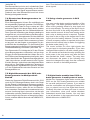
the signal cannot operate normally. At the same
time the module switches to the second level of the
configuration, which is programming for Märklin
Motorola. Fig. 1a shows an example for setting
up a multi-aspect main signal (socket Hp0) and a
distant signal on the same mast, which belongs to
the next main signal (socket Hp1).

6
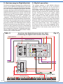
Schritt der Konfiguration über, der Programmierung
für den Einsatz im Märklin-Motorola-Format. Abb.
1a zeigt als Beispiel eine Kabelbrückung für die
Einstellung auf ein mehrbegriffiges Hauptsignal
(Buchse Hp0) und für das Signal mit am eigenen
Mast montierten Vorsignal, das zum folgenden
Hauptsignal gehört (Buchse Hp1).
5. Programmierung des
Steuermoduls
Der Programmiervorgang wird mit der Taste „Config“
auf der Oberseite des Moduls eingeleitet. Drücken
Sie die Taste „Config“ ca. 3 Sekunden, bis die rote
Kontroll-LED beginnt, langsam zu blinken.
5.1 Programmierung im Märklin-
Motorola-Format
Geben Sie jetzt mit Ihrem Digitalsystem einen
Stellbefehl mit der Adresse, die Sie für das Signal
vorgesehen haben. Das Modul wartet auf den ers-
ten eintreffenden gültigen Weichenstellbefehl und
übernimmt und speichert dessen Adresse als seine
eigene. Als Zeichen dafür erlischt die Kontroll-LED
und das Signal durchläuft den unten beschriebenen
Kontroll-Zyklus.
Bei der Konfiguration auf ein mehrbegriffiges Signal
übernimmt es eine ungerade Digital-Adresse als
erste und die darauf folgende gerade als zweite.
Deshalb würde bei einem mehrbegriffigen Signal ein
Stellbefehl für die Adresse 001 oder für die Adresse
002 das Modul in beiden Fällen auf die Adressen
001 und 002 programmieren. Die Kombination der
Adressen 002 und 003 ist nicht möglich, da dies
leicht zu Überschneidungen mit dem Adressbereich
anderer Decoder führen könnte.
5.2 Programmierung im NMRA-DCC-
Format
Ein zweiter Druck auf die Programmiertaste bringt
das Signalmodul in den Programmiermodus für
das NMRA-DCC-Format. Die LED zeigt dies durch
schnelles Blinken an. Der Ablauf der Adressüber-
nahme ist der gleiche wie beim Märklin-Motoro-
la-Format.
5.3 Beenden der Programmierung
Mit dem Empfang eines gültigen Digital-Stellbefehls
beendet das Steuermodul den Programmiervorgang
automatisch und ruft den Kontrollzyklus auf. Möchten
Sie das Modul nicht digital einsetzen, dann beendet
der dritte Druck auf die Programmiertaste ebenfalls
die Konfiguration.
Werkseinstellung: Dreimaliges Drücken der Pro-
grammiertaste (das erste Mal 3 Sekunden, bis die
LED beginnt zu blinken) ohne angeschlossene
Kabelbrücken und ohne Empfang eines digitalen
5. Programming the control
module
Start this programming process by pressing the
button “Config” at the top of the module. Press the
button “Config” for at least 3 seconds until the red
LED starts to blink slowly.
5.1 Programming for Märklin Motorola
Now enter with your digital system a switching or-
der with the address which you have intended for
the signal. The control module indicates this status
by slow blinking of the control LED. The module
waits for the first valid switch command and takes
its address as its own. The LED now indicates the
completion of this process by turning off and the
signal continues with the control cycle described
below.
When configuring the module for a multi-aspect
signal, the module accepts an uneven digital ad-
dress as its first and the subsequent even number
as the second address. Therefore, the command for
a multi-aspect signal for address 001 and 002 would
programme the module in both cases to addresses
001 and 002. The combination of addresses 002
and 003 is not permitted, since this could easily lead
to overlaps with the address of other decoders.
5.2 Programming for NMRA-DCC
A second push of the programming button takes
the module to the DCC programming mode. The
LED indicates this status by fast blinking. The pro-
cess of assigning addresses is the same as in the
Märklin Motorola format.
5.3 Finishing the programming mode
The control module automatically ends the pro-
gramming mode once it receives a valid digital
command. It then calls up the control cycle. If you
want to use the module in analogue mode, a third
push of the programming button ends also the pro-
gramming mode.
Default settings: Pushing the programming button
three times (the first time at least 3 seconds) while
there are no cable bridges connected and without
receiving any digital signals resets the module to

7
Stellbefehls konfiguriert das Signalmodul wieder auf
den werkseitigen Auslieferungszustand:
- Zweibegriffiges Signal
- Separat stehendes eigenes Vorsignal
- Nicht gekoppelt
- Bahnhofssignal-Logik
- Kein Bremsgenerator
5.4 Der Kontroll-Zyklus
Nach erfolgreicher Konfiguration durchläuft das
Steuermodul einen Kontrollzyklus. Dabei werden
zunächst alle Ausgänge für die Signal-LEDs nach-
einander einzeln ein- und wieder ausgeschaltet.
Im zweiten Schritt werden alle Ausgänge für die
Signal-LEDs nacheinander zugeschaltet. Nach
etwa einer Sekunde erlöschen alle LEDs und der
Kontroll-Zyklus ist abgeschlossen.
6. Der Viessmann Signalbus
Bei modernen Signalsystemen sind die Einzelsigna-
le voneinander abhängig bzw. das Signalbild eines
Signals wird vom folgenden Signal mit beeinflusst.
Um diese Abhängigkeiten im Modell vorbildgerecht
nachbilden zu können, werden die Signale unterei-
nander über den Viessmann-Signalbus miteinander
verbunden. Der Signalbus ist eine Datenübertragung
über 2 zusätzliche Kabel und arbeitet entgegen der
Fahrtrichtung der Züge.
Wichtig: Der Signalbus ist nicht an ein Digitalsystem
gebunden. Er funktioniert auch bei konventionellem
Betrieb ohne Einschränkungen! Der Signalbus von
Art. 5224 ist kompatibel zum Signalbus von Art. 5229
Multiplexer für Lichtsignale mit Multiplex-Technologie.
Übertragung der Signalstellung: Der Signalbus
überträgt die Stellung des Signals (die Streckenge-
schwindigkeit) an das vorhergehende, empfangende
Signal. Aus dem eigenen Stellbefehl und der erhalte-
nen Information erzeugt dieses Signal seine eigene
Stellung für Haupt- und Vorsignal. Es passt daraufhin
ggf. das Signalbild von Haupt- und Vorsignal an. Das
empfangende Signal überträgt dann seinerseits die
entsprechenden Informationen an das wiederum
davor liegende Signal.
Der Signalbus arbeitet sogar zwischen den ver-
schiedenen Signalgenerationen und -typen (z. B.
Ks-Signale und Kompaktsignale), so dass ein Über-
gang ohne zusätzliche Schaltungen oder eine
übergeordnete Instanz möglich ist!
Übertragung der Besetztmeldung: Zusätzlich zur
Information über die Signalstellung überträgt der
Signalbus auch den Besetztzustand aller an das
Signalmodul angeschlossenen Streckenabschnitte
bzw. Taster. Diese Informationen ermöglichen den
Betrieb von Signalen mit Blockstreckenautomatik!
the factory default values:
- 2-aspect signal
- Own distant signal
- Uncoupled
- Yard signal logic
- No brake generator
5.4 The control cycle
After successful configuration the module runs
through a control cycle. All outputs for signal LEDs
are switched on and off one after another. Then
all outputs are switched on one-by-one. After ap-
prox. one second all LEDs are switched off and the
control cycle is completed.
6. The Viessmann signal bus
In modern signal systems the individual signals are
dependent on each other respectively the aspect
of the signal is influenced by the following signal. In
order to simulate this interdependence the signals
are connected via the Viessmann signal bus. The
signal bus is a separate data communication with
2 wires and works against the direction of travel.
Important: The signal bus does not require a
digital system. It works in the same manner and
without any restrictions in analogous mode! The
signal bus of item 5224 is compatible with the
signal bus of item 5229 Multiplexer for colour
light signals with multiplex technology.
Transmission of the signal aspect: The signal
bus transmits the signal aspect (the speed on the
main line) to the receiving signal located one block
back. That signal generates the correct aspect
for itself and its distant signal by combining the
information contained in the command plus the
feedback from the following signal. If necessary it
changes the signal aspect of both main signals and
distant signals. The received command is in turn
transmitted to the preceding signal and so forth.
The signal bus works with different signal types
and signal generations. Therefore, no additional
circuit or higher entity is requiered.
Transmission of track occupancy status: The
signal bus not only conveys the signal aspect but
also the track occupancy status of all track sectors
connected to the module or push button inputs.
Without this information the operation with block
signals (block logic) is not possible.

8
6.1 Verzweigungen des Signalbusses
Der Viessmann-Signalbus darf sich verzweigen. Eine
zyklische Übertragung sorgt dafür, dass die Informa-
tionen kurzfristig in Richtung des neuen Fahrweges
aktualisiert werden. Die Datenübertragung folgt so
immer dem eingestellten Fahrweg. Dadurch zeigt
z. B. ein Einfahrsignal immer das richtige Bild am
Vorsignal, wenn der Signalbus parallel zur Stellung
der Weichen durch ein zweipoliges Relais mit umge-
schaltet wird (siehe Abb. 7).
Am Ausfahrsignal kann der Signalbus auf gleiche
Weise über Relais dem Fahrweg zugeordnet werden.
Der Unterschied besteht darin, dass sich hier der
Fahrweg nicht aufspaltet, sondern wieder zusam-
mengeführt wird. Deshalb werden die Relais hier in
umgekehrter Richtung betrieben (siehe Abschnitt 7.2
Blockstrecken-Logik).
7. Die Signal-Logik
Es gibt nicht nur verschiedene Signaltypen, sondern
gleiche Typen können – je nach Standort –auch
verschiedene Aufgaben übernehmen. Dadurch
unterscheidet sich ihr Verhalten im Betrieb. Es
gibt zwei Logiken: Die Bahnhofssignal-Logik und
die Blocksignal-Logik. Auf beide Logiken kann das
Viessmann-Steuermodul eingestellt werden.
7.1 Die Bahnhofssignal-Logik
Im Grundzustand steht das Bahnhofssignal auf
„Halt“. Es reagiert auf die Taster-Eingänge „Hp0“ und
„Hp1“, bei mehrbegriffigen Signalen zusätzlich auf
„Hp2“ und „Sh1“. Diese Eingänge sind immer aktiv.
Der Eingang „Hp0“, der das Signal auf „Halt“ stellt,
hat Vorrang vor allen anderen, so dass das Signal
unbedingt auf „Halt“ stehen bleibt, wenn dieser Ein-
gang betätigt wird.
Der Eingang „Bremsen“ ist nur dann aktiv, wenn Sie
einen Bremsgenerator einsetzen und Sie das Signal
entsprechend konfiguriert haben (siehe Abschnitt 7.3
Einsatz des Digital-Bremsmoduls und 7.4 Einsatz
eines Bremsgenerators).
Bei „Halt“ steuert das Signalmodul ein angestecktes
Zugbeeinflussungsrelais Art. 5228 so an, dass der
Fahrstrom im angeschlossenen Signalabschnitt
ausgeschaltet wird (siehe Abb. 8). Bei „Fahrt“ – und
ggf. auch bei „Langsamfahrt“ und „Rangierverbot
aufgehoben“ – schaltet es den Fahrstrom wieder
ein.
Setzen Sie bei einem Signal mit Bahnhofssig-
nal-Logik Mehrbereichssignale oder Signale ein,
die das Vorsignal für das folgende Signal am Mast
tragen, müssen Sie die Steuermodule durch den
Viessmann Signalbus miteinander verbinden, damit
die Mehrbereichssignale bzw. die Vorsignale das
korrekte Signalbild anzeigen.
6.1 Branches of the signal bus
The Viessmann signal bus can have branches.
Cyclical transmission assures speedy update of
status if a new route is switched. Thus the infor-
mation always travels according to the set route.
Therefore, e. g. a light entry signal always shows
the correct aspect of its distant signal, if the signal
bus is deviated parallel to the position of the points
or crossings by means of a double-pole relay (see
fig. 7).
The signal bus can be switched to match the route
for exit signals. The difference is that the route
does not branch out but several routes merge.
Therefore, the relays are wired in the opposite way
(see chapter 7.2 block signal logic).
7. The signal logic
There are not only different types of signals but the
same types may have different functions depend-
ing on their location. Therefore, their functionality
changes. There are two types of logic: The yard
signal logic and the block signal logic. The Viess-
mann control module can be set for both types.
7.1 The yard signal logic
The normal aspect of a yard signal is “stop”. It
responds to the buttons “Hp0” and “Hp1”, in case
of multi-aspect signals also to “Hp2” and “Sh1”.
These inputs are always active. The input “Hp0”
setting the signal to “stop” has precedence before
all others. Thus the signal will definitely show the
“stop” aspect if this input is activated.
The input “braking” is only active if you use a brake
generator and have configured the signal accord-
ingly (see chapter 7.3 Using the digital brake mod-
ule and 7.4 Using a brake generator).
If the signal is set to “stop” a plugged relay for train
control item 5228 will be set in that way, that it dis-
connects power from that track sector (see fig. 8). If
the signal shows “Proceed” – and maybe “Proceed
slowly” and “Shunting ban cancelled” – the power
will be reconnected.
If you use multi-sector signals or signals carrying
the distant signal of the following main signal on
their mast in yard logic, the modules have to be
connected by the Viessmann signal bus in order
to enable the signals to show the correct aspect.

9
7.2 Blockstrecken-Logik
Für den Einsatz der Blockstrecken-Logik muss
Ihre Anlage unbedingt mit einer Gleisbesetztmel-
dung ausgerüstet sein, die eine kontinuierliche Be-
setzt-/ Frei-Information liefert. Bei Märklin Gleisen
z. B. mittels Kontaktstrecken durch eine isolierte
Außenschiene oder bei Zweileiter-Systemen mit
Gleisabschnitten, die von Stromfühlern überwacht
sind. Hierzu eignet sich besonders der Viessmann
Gleisbesetztmelder, 8-fach Art. 5206.
Jeder Blockabschnitt besteht aus 2 Teilen, dem
Fahr- und dem Halteabschnitt. Der Fahrabschnitt
wird an den Eingang „Sh1“ und der Halteabschnitt
an den Eingang „Bremsen“ angeschlossen. Die Sig-
nalmodule müssen über den Signalbus miteinander
verbunden werden, denn die Besetzt-Informationen
beeinflussen hauptsächlich das vorhergehende
Signal! Bei einer Blockstrecken-Logik darf sich der
Signalbus ebenfalls verzweigen.
Im Grundzustand steht das Blocksignal auf „Fahrt“.
Meldet der Signalbus einen oder beide folgenden
Abschnitte „besetzt“, dann stellt sich das Signal au-
tomatisch auf „Halt“. Meldet der Signalbus wieder
eine freie Strecke, geht das Signal auf „Fahrt“ zurück.
Diese automatische Umschaltung auf „Fahrt“ ge-
schieht auch dann, wenn z. B. durch Umschalten
einer Weiche der Signalbus auf einen anderen
Fahrweg umgeleitet wird und dann auf die Besetzt-
meldungen eines anderen Steuermoduls reagiert,
dessen zugehöriger Streckenabschnitt frei ist.
Verliert ein Steuermodul die Signalbus-Verbindung
zum folgenden Signal und erhält deshalb über den
Signalbus keine neuen Informationen mehr, schaltet
es das Signal nach einer kurzen Wartezeit automa-
tisch auf „Halt“.
Erhält das Steuermodul die Verbindung zum folgen-
den Signal zurück und damit neue Informationen
über den Signalbus, stellt es das Signal automatisch
gemäß der neuen Informationen, d. h. Signalbild
und Besetztmeldungen, um. Auch das geschieht
erst nach einer kurzen Wartezeit.
7.3 Einsatz des Digital-Bremsmoduls Art.
5232 im Märklin-Motorola-Betrieb
Das Viessmann Bremsmodul Art. 5232 können Sie
unabhängig von der eingestellten Signallogik einset-
zen. Es sorgt dafür, dass ein Zug vor einem auf „Halt“
stehenden Signal nicht abrupt stehenbleibt, sondern
vorbildgerecht langsam bis zum Stillstand abbremst.
Dazu muss die Verdrahtung der Anlage unbedingt so
ausgeführt sein, wie es die Anleitung des Bremsmo-
duls vorschreibt. Das bedeutet eine Unterteilung des
Abschnittes vor dem Signal mindestens in einen
Fahr- und einen Halte- oder Bremsabschnitt. Beide
zusammen müssen so lang sein, wie der längste zu
erwartende Zug einschließlich des Anhalteweges
7.2 Block logic
If you want to use block logic your layout must be
equipped with track occupancy sensors contin-
uously providing the occupied/clear information.
With Märklin track this can be achieved by isolating
one outer track while tracks without centre con-
tacts require current guards in individual sectors.
We recommend the Viessmann track occupancy
detector, 8-sections item 5206.
Each block sector consists of 2 parts: the running
sector and the stop sector. The running sector has
to be connected to the “Sh1” input and the stop
sector to the “brake” input. The signal modules
have to be connected via the signal bus since the
occupancy status mainly influences the preceding
signal. Even in block logic the signal bus may have
branches.
The normal position of the block signal is “proceed”.
If the signal bus reports one or two of the following
sectors as occupied, the signal is automatically set
to “stop”. Once the signal bus reports a clear line
ahead the signal shows “proceed” again.
This automatic change to aspect “proceed” also
occurs ,e. g. if due to switching a point the signal
bus follows another route and responds by reason
of the occupancy feedback of another control mod-
ule.
Should a control module be disconnected from the
following signal and does not receive any more
information via the signal bus then the signal will
automatically change to “stop” after a short while.
If the connection to the signal bus is reinstated, the
signal will automatically be set to the appropriate
aspect. This also takes place after a short waiting
period.
7.3 Using the digital brake module item
5232 in Märklin Motorola mode
You may use the Viessmann digital brake mod-
ule item 5232 regardless of the signal logic.
It serves to slow down a train ahead of a stop sig-
nal until it stops. The wiring of the layout has to
be done as shown in the wiring diagramme of the
brake module. At least one running sector and a
stop or braking sector is required. Together they
have to be as long as the longest train on the layout
plus the braking distance (see fig. 9).
The brake module and a track occupancy module
can be wired to the same track sector at the same

10
(siehe Abb. 9).
Das Bremsmodul und eine evtl. erforderliche Gleis-
besetztmeldung können gleichzeitig an die Gleis-
abschnitte vor dem Signal angeschlossen werden.
Dadurch kann das Bremsmodul auch bei einem
Blocksignal eingesetzt werden.
7.4 Einsatz eines Bremsgenerators im
DCC-Betrieb
Einen Bremsgenerator können Sie unabhängig von
der eingestellten Signallogik einsetzen. Der Bremsge-
nerator sorgt dafür, dass ein Zug vor einem auf „Halt“
stehenden Signal nicht abrupt stehen bleibt, sondern
vorbildgerecht langsam bis zum Stillstand abbremst.
Dazu muss die Verdrahtung der Anlage unbedingt so
ausgeführt sein, wie es die Anleitung des Bremsgene-
rators vorschreibt. Normalerweise wird der Abschnitt
vor dem Signal in einen Fahr- und einen Halte- oder
Bremsabschnitt unterteilt. Beide zusammen müssen
so lang sein, wie der längste zu erwartende Zug ein-
schließlich des Anhalteweges. Für die Einleitung des
Bremsvorganges ist außerdem ein Kontakt oder eine
Gleisbesetztmeldung vorzusehen (siehe Abb. 10).
Das Steuermodul für Lichtsignale ist für den Einsatz
eines Bremsgenerators vorbereitet, weil es einen
Eingang für den Bremskontakt hat. Haben Sie es für
den Einsatz eines Bremsgenerators konfiguriert, dann
steuert das Modul das Zugbeeinflussungsrelais bei
„Halt“ nicht sofort an, sondern wartet, bis der Zug den
Kontakt „Bremsen“ erreicht hat und schaltet das Relais
dann erst um. Das Relais schaltet den Fahrstrom im
angeschlossenen Signalabschnitt nicht aus, sondern
von der Digitalzentrale oder dem Booster auf den
Bremsgenerator um.
7.5 Digital-Bremsmodul Art. 5232 oder
Bremsgenerator im Multiprotokoll-
Betrieb
Weder das Viessmann Digital-Bremsmodul Art. 5232
noch die DCC-Bremsgeneratoren sind in der Regel
für den Einsatz in Multiprotokoll-Systemen geeignet.
Möchten Sie deren komfortable und vorbildgerechte
Bremsfunktion nutzen, sollten Sie nur ein Datenfor-
mat verwenden. Das bedeutet normalerweise keine
erneute Umrüstung Ihrer Lokomotiven, da fast alle
Lokdecoder mehrere Datenformate verstehen. Sie
müssen lediglich alle Decoder auf das gleiche Daten-
format, entweder Märklin-Motorola oder NMRA-DCC,
einstellen.
time. Thus the brake module can also be used with
block signals.
7.4 Using a brake generator in DCC
mode
You may use the brake module regardless of the
signal logic. The brake generator serves to slow
down a train gradually ahead of a stop signal and
not to stop abruptly. The wiring of the layout has to
be done as shown in the wiring diagramme of the
brake module manual. At least one running sector
and a stop or braking sector is required. Together
they have to be as long as the longest train on the
layout plus the braking distance. A track contact
or track occupancy sensor is required at the place
where the train should start to brake for triggering
the brake mode (see fig. 10).
The control module for colour light signals has
its own input for the brake generator. If you have
configured the module for use with a brake genera-
tor, the module will activate the relay switching the
track power in the stop sector only after the train
has reached the “brake” contact. The relay does
not disconnect the power to the following stop
sector but changes the supply from the command
station or booster to the brake generator.
7.5 Digital brake module item 5232 or
brake generator in multi-protocol mode
Neither the Viessmann digital brake module item
5232 nor the DCC brake generators are suitable
for use with multi-protocol systems. If you want to
use the comfortable and prototypical brake func-
tion you should use only one digital data format.
Generally this does not mean you have to convert
your locomotives, since most mobile decoders
understand several data formats. You only have
to set all decoders to the same data format, either
Märklin Motorola or NMRA DCC.

11
viessmann
5224
Steuermodul für
Lichtsignale
Signal(e)
Sh1 Hp2
Hp1Hp0
┴
Brem-
sen
Signal-
Bus
Signal-
Bus
rt bn
16 V ~/
Digital
16 V ~/
Digital
rt bn
┴
┴
▼
▼
Hp Vr
1
2
1
21
2
signal bus input
buttons common
button / contact Sh1
button / contact Hp2
to further modules
button / contact Hp0
button / contact Hp1
power
signal bus output
button / contact braking
14 – 16 V AC/DC/Digital
supply
Fig. 1
Abb. 1 Polarität bei Märklin-Motorola
Polarity for Märklin Motorola

12
viessmann
5224
Steuermodul für
Lichtsignale
Signal(e)
Sh1 Hp2
Hp1Hp0
┴
Brem-
sen
Signal-
Bus
Signal-
Bus
rt bn
16 V ~/
Digital
16 V ~/
Digital
rt bn
┴
┴
▼
▼
Hp Vr
1
2
1
21
2
Stromversorgung/power supply
V AC/DC /Digital
Signalbus Eingang
Signal bus input
Fig. 1a
Abb. 1a Beispiel einer Kabelbrückung
Example of cable bridging
to further modules
signal bus output
button / contact Hp0
button / contact Hp1
14 – 16 V AC/DC/Digital
signal bus input
buttons common

13
Universal Tasten - Stellpult
5547
Viessmann
viessmann
5224
Steuermodul für
Lichtsignale
Signal(e)
Sh1 Hp2
Hp1 Hp0
┴
Brem-
sen
Signal-
Bus
Signal-
Bus
rt bn
16 V ~/
Digital
16 V ~/
Digital
rt bn
┴
┴
▼
▼
Hp Vr
1
2
1
2 1
2
Diode
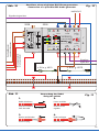
Fig. 2
Abb. 2
Anschluss an Licht-Einfahrsignal und Vorsignal
Connection to colour light entry signal and distant signal
Tasten-Stellpult 3-begriffig
5546
Viessmann
viessmann
5224
Steuermodul für
Lichtsignale
Signal(e)
Sh1 Hp2
Hp1 Hp0
┴
Brem-
sen
Signal-
Bus
Signal-
Bus
rt bn
16 V ~/
Digital
16 V ~/
Digital
rt bn
┴
┴
▼
▼
Hp Vr
1
2
1
2 1
2
Diode
Fig. 3
Abb. 3
Anschluss an Licht-Blocksignal und Vorsignal
Connection to colour light block signal and distant signal
z. B. / e. g.
4011
z. B./e. g
4012
z. B./
e. g.
4010
z. B./
e. g.
4010
Push-button panel 2-aspects, e. g. 5547
Push-button panel 3-aspects, e. g. 5546
5224
5224

14
viessmann
5224
Steuermodul für
Lichtsignale
Signal(e)
Sh1 Hp2
Hp1 Hp0
┴
Brem-
sen
Signal-
Bus
Signal-
Bus
rt bn
16 V ~/
Digital
16 V ~/
Digital
rt bn
┴
┴
▼
▼
Hp Vr
1
2
1
2 1
2
viessmann 5545
Tasten-Stellpult 4-begriffig
Diode
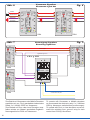
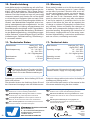
Fig. 4
Abb. 4 Anschluss an Licht-Ausfahrsignal mit Vorsignal
Connection to colour light departure signal with distant signal
z. B./e. g.
4016
Push-button panel 4-aspects, e. g. 5545
5224

15
viessmann
5224
Steuermodul für
Lichtsignale
Signal(e)
Sh1 Hp2
Hp1 Hp0
┴
Brem-
sen
Signal-
Bus
Signal-
Bus
rt bn
16 V ~/
Digital
16 V ~/
Digital
rt bn
┴
┴
▼
▼
Hp Vr
1
2
1
2 1
2
Tasten-Stellpult 2-begriffig
5547
Viessmann
Diode
Fig. 5
Abb. 5 Anschluss an Licht-Sperrsignal
Connection to colour light block signal
z. B./e. g.
4018
Push-button panel 2-aspects, e. g. 5547
5224

16
viessmann
5224
Steuermodul für
Lichtsignale
Signal(e)
Sh1 Hp2
Hp1Hp0
┴
Brem-
sen
Signal-
Bus
Signal-
Bus
rt bn
16 V ~/
Digital
16 V ~/
Digital
rt bn
┴
┴
▼
▼
Hp Vr
1
2
1
21
2
viessmann
5224
Steuermodul für
Lichtsignale
Signal(e)
Sh1 Hp2
Hp1Hp0
┴
Brem-
sen
Signal-
Bus
Signal-
Bus
rt bn
16 V ~/
Digital
16 V ~/
Digital
rt bn
┴
┴
▼
▼
Hp Vr
1
2
1
21
2
braun/brown
rot/red
grau/grey
lila/purple
Fig. 6
Abb. 6 Viessmann Signalbus
Viessmann signal bus
zur Weiche/to the point
AC/DC/Digital
Signalbus/signal bus
viessmann
5224
Steuermodul für
Lichtsignale
Signal(e)
Sh1 Hp2
┴
Signal-
Bus
rt bn
16 V ~/
Digital
16 V ~/
Digital
rt bn
┴
▼
Hp Vr
1
2
1
21
2
viessmann
5224
Steuermodul für
Lichtsignale
Signal(e)
Sh1 Hp2
Hp1Hp0
┴
Brem-
sen
Signal-
Bus
Signal-
Bus
rt bn
16 V ~/
Digital
16 V ~/
Digital
rt bn
┴
┴
▼
▼
Hp Vr
1
2
1
21
2
viessmann
5224
Steuermodul für
Lichtsignale
Signal(e)
Sh1 Hp2
┴
Signal-
Bus
rt bn
16 V ~/
Digital
16 V ~/
Digital
rt bn
┴
▼
Hp Vr
1
2
1
21
2
Elektr. Relais 5552
Viessmann
Fig. 7
Abb. 7 Verzweigung Signalbus
Branching signal bus
Zum Betrieb mit Viessmann oder Märklin Decodern
empfehlen wir von „Plus“ geschaltete elektronische
Relais 2 x 2 UM Art. 5552 von Viessmann.
Zum Betrieb mit Roco oder Lenz Decodern emp-
fehlen wir das von „Masse“ geschaltete Zugbeein-
flussungsrelais Art. 5228 von Viessmann.
z. B./e. g. 5552
To operate with Viessmann or Märklin decoders
we recommend the electronic relay 2 x 2 UM item
5552 by Viessmann, switched from positive supply.
To operate with Roco or Lenz decoders we recom-
mend the switching from „ground“ relay for train
control item 5228 by Viessmann.
5224 5224
5224
5224 5224

17
viessmann
5228
10 - 16 V
= / ~
Zugbeeinflussungs-
relais
viessmann
5224
Steuermodul für
Lichtsignale
Signal(e)
Sh1COM Hp2
Hp1Hp0
Brem-
sen
Signal
-Bus
Signal
-Bus
rt bn
16 V ~/
Digital
16 V ~/
Digital
rt bn
▼
▼
Hp Vr
1
2
1
21
2
Signalbus/signal bus
AC/DC/Digital
Signalbus/signal bus
5228 5224
Fig. 8
Abb. 8 Anschluss des Zugbeeinussungsrelais
Installation of relay for train control
z. B./e. g. 4012z. B./e. g. 4010
8. Das Vorsignal
Das Steuermodul gibt bei der Konfiguration „eigenes
Vorsignal“ das Signalbild für ein separat stehendes
Vorsignal aus, das dem Signalbild des Hauptsignals
entspricht. Dieses Vorsignalbild wird kontinuierlich an-
gezeigt. Ein Wechsel des Signalbildes erfolgt natürlich
immer mit weichem Übergang und entspricht damit
einem Vorbild-Vorsignal mit Glühlampen. Den An-
schluss des Vorsignals sehen Sie in Abb. 2, 3 und 4.
Ist das Steuermodul jedoch auf die Konfiguration
„Vorsignal am eigenen Mast“ eingestellt, dann gehört
das Vorsignal zum folgenden Hauptsignal. Es erhält
die erforderlichen Informationen über den Signalbus
und zeigt das entsprechende Signalbild an.
In den Stellungen „Halt“ oder „Rangierverbot aufgeho-
ben“ wird das Vorsignal automatisch dunkel geschaltet.
Diese „Dunkeltastung“ entspricht dem Vorbild, denn
wer nicht weiterfahren darf, braucht die Stellung des
nächsten Signals nicht zu kennen. Das eigene Vorsi-
gnal kann in diesem Fall parallel mit dem Hauptsignal
angeschlossen werden, so dass das Steuermodul ein
Hauptsignal und zwei Vorsignale steuert.
8. The distant signal
The control module sets a separate distant signal
(on its own mast) to the corresponding signal aspect
of the main signal if it is set to “own distant signal”.
The signal aspect is shown continuously. The
change of the signal aspect always occurs with a
soft change over as the prototype signal with incan-
descent lamps. The connection of the distant signal
is shown in fig. 2, 3 and 4.
If the control module is configured to “distant signal
on the same mast”, the distant signal belongs to the
following main signal. It receives its commands via
the signal bus and shows the corresponding aspect.
When the aspects “stop” or “shunting permitted”
are shown the distant signal will remain dark. This
is prototypical because if the engine or train is not
permitted to proceed outside the yard, it does not
need to know the aspect of the following signal. The
own distant signal can be connected parallel to the
main signal. Thus the control module operates one
main signal and two distant signals.

18
viessmann
5228
10 - 16 V
= / ~
Zugbeeinflussungs-
relais
viessmann
5224
Steuermodul für
Lichtsignale
Signal(e)
Sh1COM Hp2
Hp1Hp0
Brem-
sen
Signal
-Bus
Signal
-Bus
rt bn
16 V ~/
Digital
16 V ~/
Digital
rt bn
▼
▼
Hp Vr
1
2
1
21
2
Signalbus
signal bus
Signalbus/signal bus
viessmann
Digital-
Bremsmodul
5232
SBF
rt bn
STOP
Märklin-Motorola
fahren/proceed bremsen brake
5228 5224
5232
Fig. 9
Abb. 9 Anschluss des Digital-Bremsmoduls Art. 5232
Connecting the digital brake module item 5232
z. B./e. g. 4010
9. Ansteuerung im Digitalbetrieb
Das Modul benötigt zur Ansteuerung im Märklin-Mo-
torola- und im NMRA-DCC-Betrieb eine oder zwei
direkt aufeinander folgende Digital-Weichenadres-
sen. Bei einem mehrbegriffigen Signal, das zwei
Adressen benötigt, ist die erste Adresse immer eine
ungerade Adresse. Bis zu fünf externe Kontakte oder
Taster können angeschlossen werden, über die das
Signalmodul vom Zug aus geschaltet werden kann.
Vier für die Stellungen „rot“, „grün“, „grün/gelb“ und
„rangieren“. Der fünfte Anschluss („Bremsen“) ist für
den Bremskontakt, der beim Anschluss eines Brems-
generators die Umschaltung der Stromversorgung
von Fahren (Zentrale/Booster) auf Bremsen (Brems-
generator) auslöst. Ohne Bremsgenerator wird die
Fahrstromunterbrechung sofort wirksam, wenn das
Signal auf „Halt“ gestellt wird. Die Ein-/Ausschaltung
bzw. die Umschaltung des Fahrstroms übernimmt
das ansteckbare Viessmann Zugbeeinflussungsre-
lais Art. 5228 (siehe Abb. 8, oberes Gleis 2-Leiter,
unteres Gleis 3-Leiter Variante).
9. Digital operation
The module requires in both Märklin Motorola
and NMRA DCC format one or two successive
addresses. If two addresses are required (for a
multi-aspect signal) the first one is always an un-
even number. Up to five external contacts or push-
buttons may be connected for switching the signal
by train. The first four are for “red”, “green”, green/
yellow” and “shunting”.The fifth is called “braking”
and is intended for the brake generator and trig-
gers the changeover from normal supply from the
command station or booster to supply via the brake
generator. Without brake generator the interruption
of the traction current becomes effective immedi-
ately if the signal shows “stop”. The switching of
the traction current is done by the pluggable Viess-
mann relay for train control item 5228 (see fig. 8,
upper track for 2 rail version, lower track for 3 rail
version).

19
viessmann
5228
10 - 16 V
= / ~
Zugbeeinflussungs-
relais
viessmann
5224
Steuermodul für
Lichtsignale
Signal(e)
Sh1COM Hp2
Hp1Hp0
Brem-
sen
Signal
-Bus
Signal
-Bus
rt bn
16 V ~/
Digital
16 V ~/
Digital
rt bn
▼
▼
Hp Vr
1
2
1
21
2
Signalbus
signal bus
NMRA-DCC
Signalbus/signal bus
Bremsgenerator
brake generator
Zentrale/Booster
central unit/booster
5228 5224
Fig. 10
Abb. 10 Anschluss eines möglichen DCC-Bremsgenerators
Connection of a possible DCC brake generator
Stecker aufschieben
insert the plug
Draht umbiegen
bend the wire
Litzen verdrillen
twist the wires
together
Kabel abisolieren
strip the insulation
from the cable ca. 1,5 cm
1.
2.
3. 4.
Fig. 11
Abb. 11 Verwendung der Kabel
Using the cables
z. B./e. g 4012z. B./e. g. 4010

Modellbauartikel, kein Spielzeug! Nicht geeignet für
Kinder unter 14 Jahren! Anleitung aufbewahren!
Model building item, not a toy! Not suitable for children
under the age of 14 years! Keep these instructions!
Ce n’est pas un jouet! Ne convient pas aux enfants de
moins de 14 ans! Conservez cette notice d’instructions!
Não é um brinquedo! Não aconselhável para menores de
14 anos! Conservar o manual de instruções!
Modelbouwartikel, geen speelgoed! Niet geschikt voor
kinderen onder 14 jaar! Gebruiksaanwijzing bewaren!
Articolo di modellismo, non è un giocattolo! Non adatto
a bambini al di sotto dei 14 anni! Conservare istruzioni per
l’uso!
Artículo para modelismo ¡No es un juguete! No
recomendado para menores de 14 años! Conserva las
instrucciones de servicio!
DE
EN
FR
NL
IT
ES
PT
Made in Europe
Viessmann
Modelltec
hnik GmbH
Bahnhofstraße 2a
D - 35116 Hatzfeld-Reddighausen
+49 6452 9340-0
www.viessmann-modell.de
Points de collecte sur www.quefairedemesdechets.fr
À DÉPOSER
EN MAGASIN À DÉPOSER
EN DÉCHÈTERIE
OU
Cet modéle
se recycle
FR
FR
10. Gewährleistung
Jeder Artikel wurde vor Auslieferung auf volle Funk-
tionalität geprüft. Der Gewährleistungszeitraum be-
trägt 2 Jahre ab Kaufdatum. Tritt in dieser Zeit ein
Fehler auf und Sie finden die Fehlerursache nicht,
nehmen Sie bitte Kontakt mit uns auf (service@
viessmann-modell.com).Senden Sie uns den Artikel
zur Kontrolle bzw. Reparatur bitte erst nach Rück-
sprache zu. Wird nach Überprüfung des Artikels ein
Herstell- oder Materialfehler festgestellt, wird er kos-
tenlos instandgesetzt oder ausgetauscht. Von der
Gewährleistung und Haftung ausgeschlossen sind
Beschädigungen des Artikels sowie Folgeschäden,
die durch unsachgemäße Behandlung, Nichtbeach
-
ten der Bedienungsanleitung, nicht bestimmungsge-
mäßen Gebrauch, eigenmächtigen Eingriff, bauliche
Veränderungen, Gewalteinwirkung, Überhitzung u.
ä. verursacht werden.
11. Technische Daten
Datenformat: analog (AC, DC),
digital (DCC, MM)
Betriebsspannung: 10 – 16 V AC~
14 – 24 V DC=
13 – 24 V Digitalsystem
Betriebsstrom: < 150 mA
Ruhestrom: < 30 mA
10. Warranty
Each model is tested as to its full functionality prior
to delivery. The warranty period is 2 years starting
on the date of purchase. Should a fault occur dur-
ing this period please contact our service depart-
send the item to the Viessmann service depart-
ment for check and repair only after consultation.
If we find a material or production fault to be the
cause of the failure the item will be repaired free
of charge or replaced. Expressively excluded from
any warranty claims and liability are damages of
the item and consequential damages due to inap-
propriate handling, disregarding the instructions of
this manual, inappropriate use of the model, unau-
thorized disassembling, construction modifications
and use of force, overheating and similar.
11. Technical data
Data formats: analogue (AC, DC),
digital (DCC, MM)
Operating voltage: 10 – 16 V AC~
14 – 24 V DC=
13 – 24 V digital system
Operating current: < 150 mA
Stand-by current: < 30 mA
20
92075
Stand 05/fa
08/2023
Ho/Kf
Änderungen vorbehalten. Keine Haftung für Druck-
fehler und Irrtümer.
Die aktuelle Version der Anleitung finden Sie auf
der Viessmann Homepage unter der Artikelnummer.
Subject to change without prior notice. No liability for
mistakes and printing errors.
You will find the latest version of the manual on the
Viessmann website using the item number.
Entsorgen Sie dieses Produkt nicht über
den (unsortierten) Hausmüll, sondern
führen Sie es der Wiederverwertung zu.
Do not dispose of this product through (unsorted)
domestic waste, supply it to recycling instead.
-
 1
1
-
 2
2
-
 3
3
-
 4
4
-
 5
5
-
 6
6
-
 7
7
-
 8
8
-
 9
9
-
 10
10
-
 11
11
-
 12
12
-
 13
13
-
 14
14
-
 15
15
-
 16
16
-
 17
17
-
 18
18
-
 19
19
-
 20
20


in altre lingue
- English: Viessmann 5224 Owner's manual
- Deutsch: Viessmann 5224 Bedienungsanleitung
Documenti correlati
-
Viessmann 52292 Manuale del proprietario
-
-
-
-
Viessmann 5221 Manuale del proprietario
-
-
-
-
-