Viessmann 52292 Manuale del proprietario
- Tipo
- Manuale del proprietario
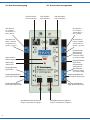
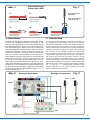
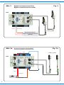
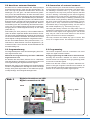
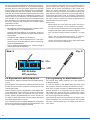
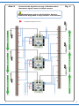
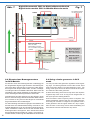
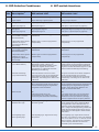
Di seguito troverai brevi informazioni per Multiplexer 52292. Questo modulo di controllo con decoder digitale integrato (MM, DCC) è progettato per il controllo di 2 segnali principali Viessmann con tecnologia multiplex. Rileva automaticamente i segnali collegati e può essere configurato in modalità digitale o analogica. Il modulo è ideale per le passerelle di segnale Viessmann. Permette anche di commutare i segnali tramite contatti di binario e comandi digitali. Tramite SpeedBus (LSB) è molto facile da collegare al Viessmann Commander con registrazione automatica.
Di seguito troverai brevi informazioni per Multiplexer 52292. Questo modulo di controllo con decoder digitale integrato (MM, DCC) è progettato per il controllo di 2 segnali principali Viessmann con tecnologia multiplex. Rileva automaticamente i segnali collegati e può essere configurato in modalità digitale o analogica. Il modulo è ideale per le passerelle di segnale Viessmann. Permette anche di commutare i segnali tramite contatti di binario e comandi digitali. Tramite SpeedBus (LSB) è molto facile da collegare al Viessmann Commander con registrazione automatica.


-
 1
1
-
 2
2
-
 3
3
-
 4
4
-
 5
5
-
 6
6
-
 7
7
-
 8
8
-
 9
9
-
 10
10
-
 11
11
-
 12
12
-
 13
13
-
 14
14
-
 15
15
-
 16
16
-
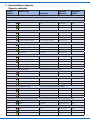 17
17
-
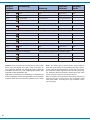 18
18
-
 19
19
-
 20
20


Viessmann 52292 Manuale del proprietario
- Tipo
- Manuale del proprietario
Di seguito troverai brevi informazioni per Multiplexer 52292. Questo modulo di controllo con decoder digitale integrato (MM, DCC) è progettato per il controllo di 2 segnali principali Viessmann con tecnologia multiplex. Rileva automaticamente i segnali collegati e può essere configurato in modalità digitale o analogica. Il modulo è ideale per le passerelle di segnale Viessmann. Permette anche di commutare i segnali tramite contatti di binario e comandi digitali. Tramite SpeedBus (LSB) è molto facile da collegare al Viessmann Commander con registrazione automatica.
in altre lingue
- English: Viessmann 52292 Owner's manual
- Deutsch: Viessmann 52292 Bedienungsanleitung
Documenti correlati
-
Viessmann 5224 Manuale del proprietario
-
Viessmann 5131 Manuale del proprietario
-
-
Viessmann 5221 Manuale del proprietario
-
-
-
-
-
-