R.V.R. Elettronica TEX50LCD/S Manuale utente
- Tipo
- Manuale utente

TEX50LCD/STEX50LCD/S
USER MANUAL
VOLUME1
Manufactured by R.V.R ELETTRONICA S.r.l. Italy

Notification of intended purpose and limitations of product use
This product is a FM transmitter intended for FM audio broadcasting. It utili-
ses operating frequencies not harmonised in the intended countries of use.
The user must obtain a license before using the product in intended country
of use. Ensure respective country licensing requirements are complied with.
Limitations of use can apply in respect of operating freuency, transmitter
power and/or channel spacing.
Declaration of Conformity
Hereby, R.V.R. Elettronica, declares that this FM transmitter is in complian-
ce with the essential requirements and other relevant provisions of Directive
2014/53/EU.
TEX50LCD/S - User Manual
Version 2.2
© Copyright 2018 - 2023
R.V.R. Elettronica S.r.l.
Via del Fonditore 2/2c - 40138 - Bologna (Italia)
Telephone: +39 051 6010506
Fax: +39 051 6011104
Email: info@rvr.it
Web: www.rvr.it
All rights reserved
Printed and bound in Italy. No part of this manual may be reproduced,
memorized or transmitted in any form or by any means, electronic
or mechanic, including photocopying, recording or by any informa-
tion storage and retrieval system, without written permission of the
copyright owner.
File Name: TEX50LCD_ENG_2.2.indb
Version: 2.2
Date: 24/03/2023
Revision History
Date Version Reason Editor
02/09/2018 2.0 Second Version J. H. Berti
06/07/2020 2.1 Technical Specication Update J. H. Berti
24/03/2023 2.2 Options Upgrade J. H. Berti

TEX50LCD/S
ELETTRONICA
i
User Manual
Rev. 2.2 - 24/03/23
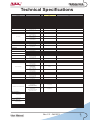
Technical Specications
TEX50LCD/S
Parameters U.M. Value Notes
Frequency range MHz 87.5 ÷ 108
Rated output power W50 Continuously variable by software from 0 to maximum
Modulation type F3E Direct carrier frequency
Operational Mode Mono, Stereo, Multiplex
Working temperature °C -5 to + 50
Working Humidity %95 (Without condensing)
Working Altitude mt 3000 With adequate air evacuation system in site
Frequency programmability From software, with 10 kHz steps
Frequency stability Working Temp. from -5°C to 50°C ppm ±1
Modulation capability kHz 150 Stereo, 180 Mono/MPX Meets or exceeds all FCC and CCIR rules
Pre-emphasis mode μS 0, 50 (CCIR), 75 (FCC) selectable by rear panel dip switches
Spurious & harmonic suppression dBc <75 (80 typical) Meets or exceeds all FCC and CCIR rules
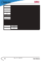
Asynchronous AM S/N ratio Referred to 100% AM,
with no de-emphasis
dB ≥ 65 (typical 70)
Synchronous AM S/N ratio
Referred to 100% AM,
FM deviation 75 kHz by 400Hz sine,
without de-emphasis
dB ≥ 50 (typical 60)
RMS @ ± 75 kHz peak,
HPF 20Hz - LPF 23 kHz,
50 μS de-emphasis
dB > 80 (typical 85)
Qpk @ ± 75 kHz peak,
CCIR weighted,
50 μS de-emphasis
dB >73
Qpk @ ± 40 kHz peak,
CCIR weighted,
50 μS de-emphasis
dB >68
Frequency Response 30Hz ÷ 15kHz dB better than ± 0.5 dB (typical ± 0.2)
Total Harmonic Distortion THD+N 30Hz ÷ 15kHz %< 0.1 (Typical 0.07%)
Intermodulation distortion
Measured with a 1 KHz,
1.3 KHz tones,
1:1ratio, @ 75 kHz FM
%< 0.05
Transient intermodulation distortion
3.18 kHz square wave,
15 kHz sine wave
@75 kHz FM
%< 0.1 (typical 0.05)
Composite S/N FM Ratio
RMS @ ± 75 kHz peak,
HPF 20Hz - no LPF,
50 μS de-emphasis
dB > 80 (typical 85)
30Hz ÷ 53kHz dB ± 0.2
53kHz ÷ 100kHz dB ± 0.5
THD+N 30Hz ÷ 53kHz %< 0.1
THD+N 53kHz ÷ 100kHz %< 0.15
Intermodulation distortion
Measured with a 1 KHz,
1.3 KHz tones,
1:1ratio, @ 75 kHz FM
%< 0.05
Transient intermodulation distortion
3.18 kHz square wave,
15 kHz sine wave
@75 kHz FM
%< 0.1 (typical 0.05)
Stereo separation 30Hz ÷ 53kHz dB > 50 dB (typical 60)
RMS @ ± 75 kHz peak,
HPF 20Hz - LPF 23 kHz,
50 μS de-emphasis,
L & R demodulated
dB > 75 (78 typical)
Qpk @ ± 75 kHz peak,
CCIR weighted,
50 μS de-emphasis,
L & R demodulated
dB > 65 dB
Qpk @ ± 40 kHz peak,
CCIR weighted,
50 μS de-emphasis,
L & R demodulated
dB > 58 dB
Frequency Response 30Hz ÷ 15kHz dB ± 0.5
Total Harmonic Distortion THD+N 30Hz ÷ 15kHz %< 0.05
Intermodulation distortion
Measured with a 1 KHz,
1.3 KHz tones,
1:1ratio, @ 75 kHz FM
%≤ 0.03
Transient intermodulation distortion
3.18 kHz square wave,
15 kHz sine wave
@75 kHz FM
%< 0.1 (typical 0.05)
Stereo separation dB > 50 (typical 55)
Main / Sub Ratio 30Hz ÷ 15kHz dB > 40 (typical 45)
Frequency response 40kHz ÷ 100kHz dB ± 0.5
RMS, ref @ ± 75 kHz peak,
no HPF/LPF,
0μS de-emphasis,
with 67 kHz tone on SCA input
@ 7,5kHz FM deviation
dB > 75 (typical 78)
RMS, ref @ ± 75 kHz peak,
no HPF/LPF,
0μS de-emphasis,
with 92 kHz tone on SCA input
@ 7,5kHz FM deviation
dB > 78 (typical 80 )
AC Supply Voltage VAC 80 ÷ 260 (*) Internal switch (**) monophase (***) Threephases Y
AC Apparent Power Consumption VA 200
Active Power Consumption W100
Power Factor 0,5
Overall Efficiency %50
Connector VDE IEC Standard
DC Supply Voltage VDC 28
DC Current ADC 8,2 (**) (*)max 25W (**) max 140W
Front panel width mm 483 (19") 19" EIA rack
Front panel height mm 88 (3 1/2") 2HE convertire in pollici
Overall depth mm 394
Chassis depth mm 372 escluso il pannello, esclusi i connettori, convertire in pollici
Weight kg about 6,5
Cooling Forced, with internal fan
Acoustic Noise dBA < 58
STEREO OPERATION
Stereo S/N FM Ratio
SCA OPERATION
Crosstalk to main or to stereo channel
POWER REQUIREMENTS
AC Power Input
DC Power Input
MECHANICAL DIMENSIONS
Phisical Dimensions
VARIOUS
Total Harmonic Distortion
GENERALS
MONO OPERATION
S/N FM Ratio
MPX OPERATION
Frequency Response

ii User Manual
Rev. 2.2 - 24/03/23
TEX50LCD/S
ELETTRONICA
Connector XLR F
Type Balanced
Impedance Ohm 10 k or 600 Selectable by rear panel dip switches
Input Level /Adjust dBu -13 to +13 continuosly variable
Connector XLR F
Type Balanced
Impedance Ohm 10 k or 600 Selectable by rear panel dip switches
Input Level dBu -13 to +13 continuosly variable
Connector BNC
Type unbalanced
Impedance Ohm 10 k or 50 Selectable by rear panel dip switches
Input Level / Adjust dBu *-13 to +13 for 75 KHz FM, externally adjustable
Connector 2 x BNC
Type unbalanced
Impedance Ohm 10 k
Input Level / Adjust dBu *-8 to +13 for 7,5 KHz FM, externally adjustable
Connector XLR F
Type Balanced
Impedance Ohm 110
Input Level / Adjust dBfs 0 to -10 for 7,5 KHz FM, externally adjustable
Connector TOS-LINk
Type Optical
Connector N type
Impedance Ohm 50
Connector BNC
Impedance Ohm 50
Output Level dB approx. -30 Referred to the RF output
Connector BNC For RDS and isofrequency synchronizing purpose
Impedance Ohm >5 k
Output Level Vpp 1
Interlock Connector BNC Input and output for remote power inhibition (short is RF off)
Service Connector DB9 F Factory reserved for firmware program
Remote Interface Connector DB15F IIC + 5 analog / digital inputs, 5 analog / digital outputs
FUSES
On Mains 1 External fuse F 6,3 T - 5x20 mm
On services
On PA Supply
On Driver Supply
Input device 4 pushbutton
Display Alphanumerical LCD - 2 x 16
10 FWD fold For P.A. A.G.C. purpose, min 0,5 Vcc
2REF fold For P.A. A.G.C. purpose, min 0,5 Vcc
14 RF ON
15 RF OFF
Close to GND 1Interlock for remote power inhibition (short is RF off)
6FWD max 5 Vcc
13 REF max 5 Vcc
5VPA max 5 Vcc
12 IPA max 5 Vcc
Open Collector 7Power Good open collector
Remote connector inputs
Analogical level
Pulse to GND
Remote connector outputs Analogical level
TELEMETRY / TELECONTROL
Right
MPX
SCA/RDS
AES/EBU
(optional)
TOS/Link
(optional)
OUTPUTS
RF Output
RF Monitor
Pilot output
AUXILIARY CONNECTIONS
HUMAN INTERFACES
Left / Mono
AUDIO INPUTS

TEX50LCD/S
ELETTRONICA
iii
User Manual
Rev. 2.2 - 24/03/23
Table of Contents
1. Preliminary Instructions 1
2. Warranty 1
3. First Aid 2
3.1 Treatment of electrical shocks 2
3.2 Treatment of electrical Burns 2
4. General Description 3
4.1 Unpacking 3
4.2 Features 4
4.3 Frontal Panel Description 5
4.4 Rear Panel Description 6
4.5 Connectors Description 7
5. Installation and use 8
5.1 Installation 9
5.2 Operation 19
5.3 Management Firmware 21
5.4 Optional Function 27
6. Identication and Access to the Modules 29
6.1 Identication of the Modules 29
7. Working Principles 30
7.1 Panel board 30
7.2 Main board 30
7.3 Telemetry board 31
7.4 Power Supply 31
7.5 Power Amplier 31
7.6 Control Board 32
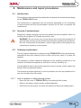
8. Maintenance and repair procedures 33
8.1 Introduction 33
8.2 Security Considerations 33
8.3 Ordinary maintenance 33
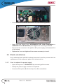
8.4 Module substitutions 34
9. Option 39
9.1 /AUDIGIN-TEX option 39
9.2 /RDS-TEX2HE & /RDS-TEX-E-2HE option 40
9.3 /TLC-TEX2HE option 41
9.4 /TLM-TEX-E-2HE option 42
9.5 /TLW-TEX-E-2HE option 43
9.6 /TLW-TEX2HE Option 44
9.7 /RTC-TEX option 45
9.8 /FW2 option (only software) 45
9.9 UP/DOWN Power option (only software) 45

iv User Manual
Rev. 2.2 - 24/03/23
TEX50LCD/S
ELETTRONICA
This page was intentionally left blank

TEX50LCD/S
ELETTRONICA
1 / 46
User Manual
Rev. 2.2 - 24/03/23
1. Preliminary Instructions
• General Warnings
This equipment should only be operated, installed and
maintained by “trained” or “qualied” personnel who are familiar
with risks involved in working on electric and electronic circuits.
“Trained” means personnel who have technical knowledge of
equipment operation and who are responsible for their own
safety and that of other unqualied personnel placed under
their supervision when working on the equipment.
“Qualified” means personnel who are trained in and
experienced with equipment operation and who are
responsible for their own safety and that of other unqualied
personnel placed under their supervision when working on
the equipment.
WARNING: Residual voltage may be present inside
the equipment even when the ON/OFF switch is set to
O. Before servicing the equipment, disconnect the
power cord or switch o the main power panel and
make sure the safety earth connection is connected.
Some service situations may require inspecting the
equipment with live circuits. Only trained and qualied
personnel may work on the equipment live and shall be
assisted by a trained person who shall keep ready to
disconnect power supply at need.
R.V.R. Elettronica shall not be liable for injury to persons or
damage to property resulting from improper use or operation
by trained/untrained and qualied/unqualied persons.
WARNING: The equipment is not water resistant.
Any water entering the enclosure might impair proper
operation. To prevent the risk of electrical shock or
re, do not expose this equipment to rain, dripping or
moisture.
Please observe local codes and re prevention rules when
installing and operating this equipment.
WARNING: This equipment contains exposed
live parts involving an electrical shock hazard. Always
disconnect power supply before removing any covers
or other parts of the equipment.
Ventilation slits and holes are provided to ensure reliable
operation and prevent overheating; do not obstruct or
cover these slits. Do not obstruct the ventilation slits under
any circumstances. The product must not be incorporated
in a rack unless adequate ventilation is provided or the
manufacturer’s instructions are followed closely.
WARNING: This equipment can radiate
radiofrequency energy and, if not installed in compliance
with manual instructions and applicable regulations,
may cause interference with radio communications.
WARNING: This equipment is tted with earth
connections both in the power cord and for the chassis.
Make sure both are properly connected.
Operation of this equipment in a residential area may cause
radio interference, in which case the user may be required
to take adequate measures.
The specications and data contained herein are provided
for information only and are subject to changes without
prior notice. R.V.R. Elettronica disclaims all warranties,
express or implied.While R.V.R. Elettronica. attempts to
provide accurate information, it cannot accept responsibility
or liability for any errors or inaccuracies in this manual,
including the products and the software described herein.
R.V.R. Elettronica reserves the right to make changes to
equipment design and/or specications and to this manual
at any time without prior notice.
• Notice concerning product intended purpose and use
limitations.
This product is a radio transmitter suitable for frequency-
modulation audio radio broadcasting. Its operating
frequencies are not harmonised in designated user countries.
Before operating this equipment, user must
obtain a licence to use radio spectrum from the
competent authority in the designated user country.
Operating frequency, transmitter power and other
characteristics of the transmission system are subject to
restrictions as specied in the licence.
2. Warranty
La R.V.R. Elettronica warrants this product to be free from
defects in workmanship and its proper operation subject to
the limitations set forth in the supplied Terms and Conditions.
Please read the Terms and Conditions carefully, as purchase
of the product or acceptance of the order acknowledgement
imply acceptance of the Terms and Conditions.
For the latest updated terms and conditions, please visit our web
site at WWW.RVR.IT. The web site may be modied, removed
or updated for any reason whatsoever without prior notice.
The warranty will become null and void in the event the
product enclosure is opened, the product is physically
damaged, is repaired by unauthorised persons or is used for
purposes other than its intended use, as well as in the event
of improper use, unauthorised changes or neglect.
In the event a defect is found, follow this procedure:
1 Contact the seller or distributor who sold the equipment;
provide a description of the problem or malfunction for
the event a quick x is available.
Sellers and Distributors can provide the necessary
information to troubleshoot the most frequently encountered
problems. Normally, Sellers and Distributors can oer a
faster repair service than the Manufacturer would. Please
note that Sellers can pinpoint problems due to wrong
installation.
2 If your Seller cannot help you, contact R.V.R.
Elettronica. and describe the problem; if our sta deems
it appropriate, you will receive an authorisation to return
the equipment along with suitable instructions;
3 When you have received the authorisation, you may
return the unit. Pack the unit carefully before shipment;
use the original packaging whenever possible and seal
the package perfectly. The customer bears all risks of
loss (i.e., R.V.R. shall not be liable for loss or damage)
until the package reaches the R.V.R. factory. For this
reason, we recommend insuring the goods for their full
value. Returns must be sent on a C.I.F. basis (PREPAID)
to the address stated on the authorisation as specied
by the R.V.R. Service Manager.
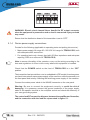
IMPORTANT
The symbol of lightning inside a triangle placed on the product, evidences the operations for
which is necessary gave it full attention to avoid risk of electric shocks.
The symbol of exclamation mark inside a triangle placed on the product, informs the user
about the presence of instructions inside the manual that accompanies the equipment, im-
portant for the ecacy and the maintenance (repairs).

2 / 46 User Manual
Rev. 2.2 - 24/03/23
TEX50LCD/S
ELETTRONICA
Units returned without a return authorisation may
be rejected and sent back to the sender.
4 Be sure to include a detailed report mentioning all
problems you have found and copy of your original
invoice (to show when the warranty period began) with
the shipment.
Please send spare and warranty replacement parts orders to
the address provided below. Make sure to specify equipment
model and serial number, as well as part description and
quantity.
R.V.R. Elettronica
Via del Fonditore, 2/2c
40138 BOLOGNA ITALY
Tel. +39 051 6010506
3. First Aid
All personnel engaged in equipment installation, operation
and maintenance must be familiar with rst aid procedures
and routines.
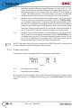
3.1 Electric shock treatment
3.1.1 If the victim is unconscious
Follow the rst aid procedures outlined below.
• Lay the victim down on his/her back on a rm
surface.
• the neck and tilt the head backwards to free
the airway system (Figure 1).
Figure 1
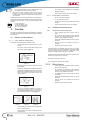
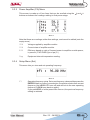
• If needed, open the victim’s mouth and check
for breathing.
• If there is no breathing, start articial respiration
without delay (Figure 2) as follows: tilt the head
backwards, pinch the nostrils, seal your mouth
around the victim’s mouth and give four fast
rescue breaths.
Figure 2
• Check for heartbeat (Figure 3); if there is
no heartbeat, begin chest compressions
immediately (Figure 4) placing your hands in
the centre of the victim’s chest (Figure 5).
Figure 3 Figure 4 Figure 5
• One rescuer: give 2 quick rescue breaths after
each 15 compressions.
• Two rescuers: one rescue breath after each 5
compressions.
• Do not stop chest compressions while giving
articial breathing.
• Call for medical help as soon as possible.
3.1.2 If the victim is conscious
• Cover victim with a blanket.
• Try to reassure the victim.
• Loosen the victim’s clothing and have him/her
lie down.
• Call for medical help as soon as possible.
3.2 Treatment of electric burns
3.2.1 Large burns and broken skin
• Cover affected area with a clean cloth or
linen.
• Do not break any blisters that have formed;
remove any clothing or fabric that is stuck to
the skin; apply adequate ointment.
• Administer adequate treatment for the type of
accident.
• Get the victim to a hospital as quickly as
possible.
• Elevate arms and legs if injured.
If medical help is not available within an hour, the victim is
conscious and is not retching, administer a solution of table
salt and baking soda (one teaspoon of table salt to half
teaspoon of baking soda every 250 ml of water).
Have the victim slowly drink half a glass of solution for four
times during a period of 15 minutes.
Stop at the rst sign of retching.
Do not administer alcoholic beverages.
3.2.2 Minor burns
• Apply cold (not ice cold) strips of gauze or dress
wound with clean cloth.
• Do not break any blisters that have formed;
remove any clothing or fabric that is stuck to
the skin; apply adequate ointment.
• If needed, have the victim change into clean,
dry clothing.
• Administer adequate treatment for the type of
accident.
• Get the victim to a hospital as quickly as
possible.
• Elevate arms and legs if injured.

TEX50LCD/S
ELETTRONICA
3 / 46
User Manual
Rev. 2.2 - 24/03/23
4. General Description
The TEX50LCD/S, manufactured by R.V.R. Elettronica, is an exciter for
Frequency Modulated audio broadcasting in a frequency modulation able to
transmit in the band between 87.5 and 108 MHz, in step of 10 KHz, with an RF
output power adjustable up to a maximum of 50 W into a 50 Ohm standard load.
The unit is factory aligned and calibrated at the time of manufacture. Because of
this manufacture process, there is no eld tune-up or alignment necessary.
Factory tolerances are:
- Maximum Output Rated Power: 47 dBm ±1 dB
- Minimum Output Rated Power: 37 dBm ±1 dB
- Gain: Not Applicable (the equipment is supplied without a radiant system, that
shall be borne by the customer).
The TEX50LCD/S are designed to being contained into a 19” rack box of 2HE.
4.1 Unpacking
The package contains:
1 TEX50LCD/S
1 User Manual
1 Mains power cables
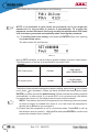
The following accessories are also available from Your R.V.R. Dealer:
• Options for the equipment:
/AUDIGIN-
TEX
/RDS-
TEX2HE
/RDS-
TEX-E-
2HE
/TLC-
TEX2HE
/TLM-
TEX2HE
/TLW-
TEX2HE
/TLW-
TEX-E-
2HE
/RTC-
TEX
/FW2
/AUDIGIN-TEX
●
●
●
●
●
●
●
●
/RDS-TEX2HE
●
X
●
●
●
●
●
●
/RDS-TEX-E-2HE
●
X
●
●
●
●
●
●
/TLC-TEX2HE
●
●
●
X
X
X
●
●
/TLM-TEX2HE
●
●
●
X
X
X
●
●
/TLW-TEX2HE
●
●
●
X
X
X
●
●
/TLW-TEX-E-2HE
●
●
●
X
X
X
●
X
/RTC-TEX
●
●
●
●
●
●
●
●
/FW2
●
●
●
●
●
●
X
●
●: compatible option / ○: option already included / x : not compatible option
Table 4.1: table of compatibility of the various options
• Spare parts
• Cables

4 / 46 User Manual
Rev. 2.2 - 24/03/23
TEX50LCD/S
ELETTRONICA
4.2 Features
This exciter contain a low-pass lter that reduces the harmonic emission to provided
for by international standards (CCIR, FCC or ETSI) and can be connected directly
to the antenna.
Two major features of TEX50LCD/S are compact design and user-friendliness.
Design is based on a modular concept: the dierent functions are performed
by modules that, for the most part, are connected through male and facilitates
maintenance and module replacement.
The RF power section of the TEX50LCD/S features a MOSFET module delivering
up to 50W output power.
Operating frequency stability is ensured by a temperature-compensated reference
oscillator and is maintained by a PLL (Phase Locked Loop) system. The exciter
will go into frequency lock within 30 seconds after power-on.
The TEX50LCD/S can operate throughout the frequency bank with no need for
calibration or set-up.
An LCD on the front panel and a push-button board provide for user interfacing
with the microprocessor control system, which oers the following features:
• Output power setup.
• Operating frequency setup.
• Power output enable/disable.
• Power Good feature (User-selectable output power alarm threshold).
• Measurement and display of transmitter operating parameters.
• Communication with external devices such as programming or telemetry
systems via RS232 serial interface or I2C.
Four LEDs on the front panel provide the following status indications: ON, LOCK,
FOLDBACK and RF MUTE.
The exciter have an input for the external 24 Vcc supply. This auxiliary supply
source, that can be realized by the user with the help of rescue batteries, is
automatically used in case of AC voltage absence.
The exciter management rmware is based on a menu system. User has four
navigation buttons available to browse submenus: ESC , , , ed ENTER.

TEX50LCD/S
ELETTRONICA
5 / 46
User Manual
Rev. 2.2 - 24/03/23
The rear panel features the mains input connectors, as well as audio input
connectors and RF output connector, telemetry connector, protection fuses and
two inputs for signals modulated onto subcarriers by suitable external coders, such
as RDS (Radio Data System) signals commonly used in Europe.
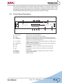
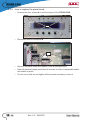
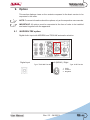
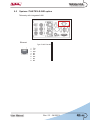
4.3 Frontal Panel Description
o
® ®®
«
� «
z
z
�o
w
□
«
o
®®®
7
M
□
D,
-L
©
I
o
®
®
® ®
o
1 2
[1] AIR FLOW Air ow for the forced ventilation.
[2] ON Green LED, lit when the exciter is working.
[3] LOCK Green led, lit when the PLL is locked on the working frequency.
[4] FOLDBACK Yellow LED, lit when the foldback function is operating (automatic
reduction of the delivered RF power).
[5] R.F. MUTE Yellow LED, lit when the exciter’s power output is inhibited by an
external interlock command.
[6] CONTRAST Display contrast adjusting trimmer (on the top of the equipment).
[7] ESC Push button to exit from a menu.
[8] Push button to move in the menu system and to modify the
parameters.
[9] Push button to move in the menu system and to modify the
parameters.
[10] ENTER Push button to conrm a parameter and to enter in a menu.
[11] DISPLAY Liquid crystals display.
[12] POWER ON/OFF switch.

6 / 46 User Manual
Rev. 2.2 - 24/03/23
TEX50LCD/S
ELETTRONICA
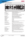
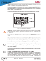
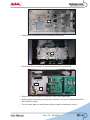
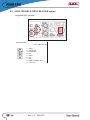
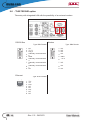
4.4 Rear Panel Description
[1] PLUG VDE plug for mains supply.
[2] FAN Fan for the forced ventilation of the exciter.
[3] R.F. OUTPUT RF output connector, N-type, 50Ω.
[4] PHASE ADJ Phase adjustment trimmer.
[5] PILOT LVL Pilot tone adjustment trimmer.
[6] MODE/MPX IMP Dip-switch to set the operation mode (STEREO or MONO)
and the MPX input impedance, 50Ω or 10kΩ.
[7] SCA 1/RDS BNC connector, SCA 1/RDS unbalanced input.
[8] MPX BNC connector, MPX unbalanced input.
[9] MPX ADJ Adjustment trimmer for MPX input.
[10] SCA 1/RDS ADJ Adjustment trimmer for SCA 1/RDS input.
[11] RIGHT ADJ Adjustment trimmer for the Right channel input.
[12] RIGHT XLR connector, balanced Right channel input.
[13] TOSLINK Not used.
[14] ADJ R Not used.
[15] ADJ L Not used.
[16] SLOT Not used.
[17] SERVICE/RDS DB9 connector for interconnection with other devices and for
factory parameters programming.
[18] 24VDC IN Not used.
[19] FUSE BLOCK Fuse carrier.Use a screwdriver to access the fuse.
[20] R.F. TEST POINT RF test output, approx. 20 dBm wrt the RF output power
level.
[21] CARRIER FREQ. ADJ Fine adjustment trimmer for the carrier frequency.
[22] PREEMPHASIS Dip-switch to set the preemphasis at 50 or 75 μs. The
preemphasis setting is relevant only for the Left and Right
inputs in stereo mode and for the mono input in mono mode,
while MPX input is unaected by this setting.
[23] 19KHZ PILOT OUT BNC output for the 19 kHz pilot tone. This can be used for
external devices (e.g. RDS coders) synchronization.
[24] SCA 2 BNC connector, SCA2 unbalanced input.
[25] SCA2 ADJ Adjustment trimmer for SCA2 input.
[26] LEFT/MONO ADJ Adjustment trimmer for LEFT/MONO channel input.
[27] LEFT/MONO XLR connector, balanced LEFT/MONO channel input.
[28] IMPEDANCE Dip-switch to set the balanced input impedance, 600Ω or
10kΩ.
[29] AES/EBU Not used.
[30] INTERLOCK IN Interlock input BNC connector: the transmitter is forced in
stand-by mode by grounding the central conductor.

TEX50LCD/S
ELETTRONICA
7 / 46
User Manual
Rev. 2.2 - 24/03/23
[31] RFL EXT. AGC Trimmer for automatic gain control based on external signal
of reected power.
[32] FWD EXT. AGC Trimmer for automatic gain control based on external signal
of forward power.
[33] RS232 Not used.
[34] REMOTE DB15 connector for telemetry of the machine.
[35] MODEM Non used.
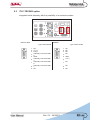
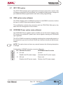
4.5 Connectors Description
4.5.1 Left (MONO) / Right
Type: Female XLR
1 GND
2 Positive
3 Negative
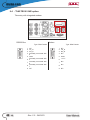
4.5.2 Remote
Type: Female DB15
Pin Name Type Meaning
1 Interlock IN By passes power if closed at GND
2 Ext AGC FWD IN Ext. signal,1-12V, for power
limitation (AGC)
3 GND Ground
4 SDA IIC I/O IIC communication serial data
5 VPA Tlm ANL OUT PA power supply voltage 3,9V F.S.
6 FWD Tlm ANL OUT Forward power 3,9V F.S.
7 Power Good DIG OUT Open collector, enabled whenpower
exceeds the set threshold
8 GND Ground
9 GND Ground
10 Ext AGC RFL IN Ext. signal.,1-12V, for power
limitation (AGC)
11 SCL IIC I/O IIC communication clock
12 IPA Tlm ANL OUT PA power supply current 3,9V F.S.
13 RFL Tlm ANL OUT Reected power 3,9V F.S.
14 On cmd DIG IN One grounded pulse (500 ms)
enables power supply
15 OFF cmd DIG IN One grounded pulse (500 ms)
disables power supply.

8 / 46 User Manual
Rev. 2.2 - 24/03/23
TEX50LCD/S
ELETTRONICA
5. Installation and use
This section provides a step-by-step description of equipment installation and
conguration procedure. Follow these procedures closely upon rst power-on
and each time any change is made to general conguration, such as when a new
transmission station is added or the equipment is replaced.
IMPORTANT: always remove the mains voltage before carrying out any type of
installation and/or maintenance. It is essential to interrupt the power supply to
avoid the risk of electric shock which could cause material damage to people or
property, serious injuries and even death.
The equipment must only be installed by qualied personnel.
With qualied personnel, it identies personnel who respond to all directives, laws
and regulations concerning safety, applicable to installation and operation of this
device.
The choice of qualied, and appropriately trained, personnel is always under
responsibility of the company in which this personnel is a part, because is the
company in question that determines whether a worker is suitable for a particular
job, in order to protect its safety by respecting the applicable law on workplace
safety matter.
These companies must provide appropriate training to their sta on electrical
devices, and make sure that they familiarize themselves with the contents of this
manual.
The respect of the safety instructions set, forth in this manual or in the specied
legislation, does not exempt you from compliance with other specic regulations
regarding installation, place, Country or other circumstances affecting the
equipment.
IMPORTANT: there is a possible danger due electric shock, therefore it is mandatory
to comply with the applicable law on safety with regard to electrical aspects.
Once the desired conguration has been set up, no more settings are required
for normal operation; at each power-up (even after an accidental shutdown),
the equipment defaults to the parameters set during the initial conguration
procedure.
The topics covered in this section are discussed at greater length in the next
sections, with detailed descriptions of all hardware and rmware features and
capabilities. Please see the relevant sections for additional detail.
IMPORTANT: When conguring and testing the transmitter in which the equipment
is integrated, be sure to have the Final Test Table supplied with the equipment ready
at hand throughout the whole procedure; the Final Test Table lists all operating
parameters as set and tested at the factory.

TEX50LCD/S
ELETTRONICA
9 / 46
User Manual
Rev. 2.2 - 24/03/23
5.1 Preparation
5.1.1 Preliminary Requirements
The equiment ventilation and the work space must be suitable for maintenance
operations according to the directive in force in the country in which this device
is installed.
It is necessary to leave a minimum distance of 50 cm on the front and back sides
of the device to have a proper functioning and to facilitate air circulation through
the ventilation grids.
In any case, the device must respect the distance established by the safety directive
in force in the country where this equipment is installed.
This device is designed to operate at -10 °C to 45 °C without loss of performance.
The ambient air must be clean of dust and not condensed; the maximum humidity
must never exceed 95%.
It is important to remember that strong changes in temperature can lead to
generation of condensation, in particular environmental conditions. In case of the
station where this device is located should be subjected to these physical events,
it is good to monitor these devices, once you put it into service, in addition to trying
to protect the device itself as much as possible.
IMPORTANT: never supply voltage to the equipment in presence of condensation.
This problem can occur more frequently in devices warehoused for a long time or
in those used as an active reserve.
The antenna RF, power supply and connection cables must have the section
suitable for the maximum current intensity.
5.1.2 Preliminary checks
Unpack the transmitter and immediately inspect it for transport damage. Check
carefully that all the connectors are in perfect condition and check for the absence
of humidithy. Otherwise, wait until it is completely dry.
In case of problems in this step, immediately contact after-sales assistance.
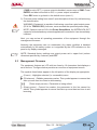
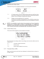
The mains power supply protection fuses are conveniently located externally on
rear panel. Remove the fuse holder with a screwdriver to check its integrity or to
replace it if necessary. The following fuse are used:

10 / 46 User Manual
Rev. 2.2 - 24/03/23
TEX50LCD/S
ELETTRONICA
TEX50LCD/S
@ 90÷260 Vac
Mains fuses (1x) 3.15A tipo 5x20
Table 5.1: Fuses
5.1.3 Placement of equipment
Useful tips for a correct installation:
• Do not use in presence of external elements near inlets and outlets ventilation
systems, as they could prevent a proper ventilation of the device.
• Do not place near any source of heat or ammable gas.
• Avoid places subject to accumulation of humidity, dust, sand, salt or environments
that could compromise the correct operation of the equipment.
• Avoid installing the equipment into inhabited places due to possible noise
pollution or on fragile supports. The operation of the equipment can cause a
noise due to forced ventilation. The mounting surface must be able to withstand
the weight of the device and must be sturdy.
Note: below we will refer to a complete station, where the device can be a part of
it. The same procedures also apply in case of the device is used individually.
The device is usually connected inside a 19 “rack and xed with M5 screws in the
appropriate holes.
The equipment must be installed at least 1 mt from the ground.
Install the rack in the point in which the transmitter will be put in operation. The
rack is mounted on wheels for easy movement so that, once placed in the desired
location, it is advisable to use the four screws located at the base of the rack to
stabilize it perpendicularly to ground.
The environment, where you have decided to install the rack, should be set up
for about 25°C of air conditioning and equipped with a lter to remove dust and
salt air.

TEX50LCD/S
ELETTRONICA
11 / 46
User Manual
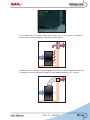
Rev. 2.2 - 24/03/23
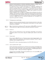
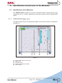
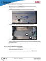
The transmitter normally have the outlet air in the back of machine.
In this case, provide adequate ventilation of the room.
COLD
HOT
50cm
In alternative is cooled by forced ventilation and the air outlet is located on the roof
of machine. Is recommended a length of tube approximetively of 1,5 meter.
COLD
HOT
50cm

12 / 46 User Manual
Rev. 2.2 - 24/03/23
TEX50LCD/S
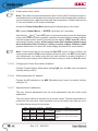
ELETTRONICA
Is highly recommended to install the rack at least 50 cm from the rear and side
wall so as to allow an optimum air ow and to facilitate workers.
50cm
50cm
COLD
HOT
5.1.3.1 Rack power supply connections
Provide for the following (applicable to operating tests and putting into service):
√ Mains power supply full range 80 ÷ 260 VAC full-range for TEX50LCD/S, both
with adequate earth connection.
√ For operating tests only: dummy load with 50 Ohm impedance and adequate
capacity (50W as a minimum for TEX50LCD/S).
Connect the overall power cord of machine. The cable can be slid through the
cable gland located on the back, or on the roof, of the machine and conductors
must be attached to the general disconnecting switch terminals.
Note: The connection of machine to power supply is done by xing a multi-pole
cable with exposed terminals to a terminal board. Make sure, with no possibility
of error, that the cable is not under tension when you connect it to the machine.
WARNING: Is highly recommended to don’t turn on the machine without rst
having connected the RF output to antenna or dummy load!
If you have a dummy load capable to dissipate the RF power generated by the
transmitter, it is advisable to carry out rst tests by linking to it rather than to the
transmission antenna.
If transmitter require a single-phase power with F (black or brown or grey) + N
(blue) + GND (green yellow), keep in mind this requirement to connect to your
distribution board.

TEX50LCD/S
ELETTRONICA
13 / 46
User Manual
Rev. 2.2 - 24/03/23
L
N
PE
If transmitter require three-phase power with 3F (black, brown and grey) + N
(blue) + GND (green yellow), keep in mind this requirement to connect to your
distribution board.
R
S
T
N
PE
Note: the mains must be equipped with adequate earth connection properly
connected to the equipment. This is a pre-requisite for ensuring operator safety
and correct operation.
The following table shows the recommended cable cross-sections:
CONNECTOR
THREE-PHASE
CABLE SECTION
SINGLE-PHASE
CABLE SECTION
L/ Ø 6mm
RØ 4mm /
SØ 4mm /
TØ 4mm /
NØ 4mm Ø 6mm
PE Ø 4mm Ø 6mm
Tipically the distribution board contains the thermal-magnetic circuit breakers for
each amplier included in the system and one for service.

14 / 46 User Manual
Rev. 2.2 - 24/03/23
TEX50LCD/S
ELETTRONICA
WARNING: Electric shock hazard! Never handle the RF output connector
when the equipment is powered on and no load is connected. Injury or death
may result.
Ensure that the distribution board of the transmitter is set to “OFF”.
5.1.4 Device power supply connections
Provide for the following (applicable to operating tests and putting into service):
√ Mains power supply full range 80 ÷ 260 VAC full-range for TEX50LCD/S, both
with adequate earth connection.
√ For operating tests only: dummy load with 50 Ohm impedance and adequate
capacity (50W as a minimum for TEX50LCD/S).
Note: to ensure the safety of the operators, carry out the wiring according to the
laws and regulations in force in the country where this equipment is installed.
Check that the POWER switch on the front of TEX50LCD/S is in the “OFF”
position.
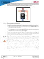
The transmitter has two switches: one is embedded in VDE socket for mains power
cord and interrupts all mains power supply of the machine, while the second is on
the front panel and acts by inhibiting the switching power supply of the machine.
Connect the mains power cable to the MAINS connector on the rear panel.
Warning: Be sure to connect the equipment correctly, to avoid the risk of
damaging. It is necessary connect the ground conductor of the power supply
cable to the specic terminal in the multipole socket and check the eciency of
your own grounding system.
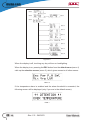
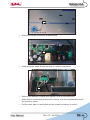
The control and RF connection diagram, between the amplier and its exciter,
and the connection with the load are represented in gure 5.1.
La pagina si sta caricando...
La pagina si sta caricando...
La pagina si sta caricando...
La pagina si sta caricando...
La pagina si sta caricando...
La pagina si sta caricando...
La pagina si sta caricando...
La pagina si sta caricando...
La pagina si sta caricando...
La pagina si sta caricando...
La pagina si sta caricando...
La pagina si sta caricando...
La pagina si sta caricando...
La pagina si sta caricando...
La pagina si sta caricando...
La pagina si sta caricando...
La pagina si sta caricando...
La pagina si sta caricando...
La pagina si sta caricando...
La pagina si sta caricando...
La pagina si sta caricando...
La pagina si sta caricando...
La pagina si sta caricando...
La pagina si sta caricando...
La pagina si sta caricando...
La pagina si sta caricando...
La pagina si sta caricando...
La pagina si sta caricando...
La pagina si sta caricando...
La pagina si sta caricando...
La pagina si sta caricando...
La pagina si sta caricando...
La pagina si sta caricando...
La pagina si sta caricando...
La pagina si sta caricando...
La pagina si sta caricando...
-
 1
1
-
 2
2
-
 3
3
-
 4
4
-
 5
5
-
 6
6
-
 7
7
-
 8
8
-
 9
9
-
 10
10
-
 11
11
-
 12
12
-
 13
13
-
 14
14
-
 15
15
-
 16
16
-
 17
17
-
 18
18
-
 19
19
-
 20
20
-
 21
21
-
 22
22
-
 23
23
-
 24
24
-
 25
25
-
 26
26
-
 27
27
-
 28
28
-
 29
29
-
 30
30
-
 31
31
-
 32
32
-
 33
33
-
 34
34
-
 35
35
-
 36
36
-
 37
37
-
 38
38
-
 39
39
-
 40
40
-
 41
41
-
 42
42
-
 43
43
-
 44
44
-
 45
45
-
 46
46
-
 47
47
-
 48
48
-
 49
49
-
 50
50
-
 51
51
-
 52
52
-
 53
53
-
 54
54
-
 55
55
-
 56
56


R.V.R. Elettronica TEX50LCD/S Manuale utente
- Tipo
- Manuale utente
in altre lingue
Documenti correlati

Altri documenti
-
Yamaha CBX-D5 Manuale utente
-
Crown IC-150 Manuale utente
-
WisyCom MTK952 Manuale utente
-
-
Aeroflex 2944B Istruzioni per l'uso
-
-
Peavey Multi-Effects Bass Preamp Manuale utente
-
Raymarine Ray 106 Manuale utente
-
-