
Metal Standalone Keypad Access Control
User Manual
EU
DE
FR
IT
ES

CONTENTS
Description
Features
Specifications
Packing List
Installation
Wiring
To Reset to Factory Default
Sound and Light indication
Detailed Programming Guide
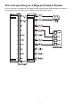
The unit operating as a Wiegand Output
Reader
INHALT
Beschreibung
Eigenschaften
Spezifikationen
Paketdetails
Installation
Verkabelung
Zurücksetzen auf Werkseinstellungen
Gebrauchsanweisungen
Detaillierte Programmieranleitung
Das Gerät arbeitet als Wiegand
Output Reader
Catalogue
Description
Caractéristiques
Spécification
Contenu de l’emballage
Installation
Câblage
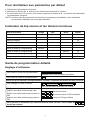
Pour reinitialiser les réglages par défaut
Indicateur de bip sonore et les témoins
lumineux
Guide de programmation détaillé
L'unité fonctionnant comme un lecteur
de sortie Wiegand
.................................................01
.....................................................01
.............................................01
...............................................02
..................................................02
.........................................................02
......................04
........................04
....................04
........................................................07
............................................01
............................................01
...........................................01
.............................................02
..................................................02
...............................................02
........04
............................04
...............04
.............................................07
.................................................01
.........................................01
...............................................01
.............................02
..................................................02
......................................................02
....04
.....................................................04
...............04
......................................07
CONTENUTO
Descrizione
Caratteristiche
Specificazione
Lista imballaggio
Installazione
Schema cablaggio
Ripristinare i valori predefiniti di fabbrica
Indicazione suono e LED
Guida alla programmazione dettagliata
L'unità funziona come un lettore di uscita
Wiegand
CONTENIDO
Descripción
Caractéristiques
Especificaciones
Lista de embalaje
Instalación
Cable
Restaura la configuración de fábrica
Indicación de sonido y luz
Guía detallada de programación
La unidad funciona como un lector de
salida Wigeand
WARNING ................................................. 08
.................................................01
............................................01
............................................01
........................................02
...............................................02
.....................................02
...04
............................04
.....04
.....................................................07
................................................01
.........................................01
........................................01
.......................................02
..................................................02
..........................................................02
.........04
..........................04
................04
.........................................07

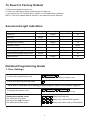
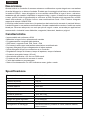
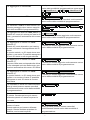
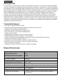
Operating Voltage DC 12V±10%
User Capacity 2000
Card Reading Distance
3-6 cm
Active Current
<
60mA
Idle Current 25±5 mA
Lock Output Load
Max 3A
Operating Temperature
-45
℃~
60
℃
Operating Humidity 10%- 90% RH
Waterproof
Conforms to IP68
Adjustable Door Relay time
0 -99 seconds
Wiegand Interface
Wiegand 26 bit
Wiring Connections
Electric Lock, Exit Button, External Alarm,External reader
1
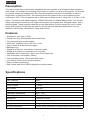
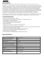
Description
The unit is single door multifunction standalone access controller or a Wiegand output keypad or
card reader. It is suitable for mounting either indoor or outdoor in harsh environments. It is housed
in a strong, sturdy and vandal proof Zinc Alloy electroplated case which is available in either a
bright silver or matt silver finish. The electronics are fully potted so the unit is waterproof and
conforms to IP68. This unit supports up to 2000 users in either a Card, 4 digit PIN, or a Card + PIN
option. The inbuilt card reader supports 125KHZ EM cards,13.56MHz Mifare cards. The unit has
many extra features including lock output current short circuit protection, Wiegand output , and a
backlit keypad. These features make the unit an ideal choice for door access not only for small
shops and domestic households but also for commercial and industrial applications such as
factories, warehouses, laboratories, banks and prisons.
Features
• Waterproof, conforms to IP68
• Strong Zinc Alloy Electroplated anti-vandal case
• Full programming from the keypad
• 2000 uses, supports Card, PIN, Card + PIN
• Can be used as a stand alone keypad
• Backlight keys
• Wiegand 26 input for connection to external reader
• Wiegand 26 output for connection to a controller
• Adjustable Door Output time, Alarm time, Door Open time
• Very low power consumption (30mA)
• Fast operating speed, <20ms with 2000 users
• Lock output current short circuit protection
• Easy to install and program
• Red, Yellow and Green LEDS display the working status
Specifications
English

Please ensure that all the above contents are correct. If any are missing please notify the supplier
of the unit.
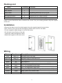
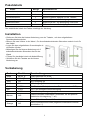
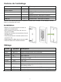
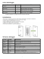
Installation
• Remove the back cover from the keypad using the supplied special screw driver
• Drill 2 holes on the wall for the Self tapping screws and I hole for the cable
• Put the supplied rubber bungs to into the two holes
• Fix the back cover firmly on the wall with 2 Self tapping screws
• Thread the cable through the cable hole
• Attach the keypad to the back cover
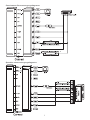
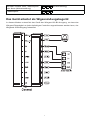
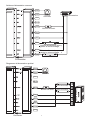
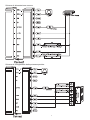
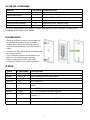
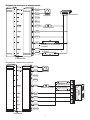
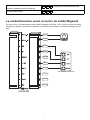
Wiring
2
Colour
Function
Description
Pink
BELL_A
Doorbell button one end
Pale blue
BELL_B
Doorbell button to the other end
Green D0 WG output D0
White
D1
WG output D1
Yellow OPEN Exit button one end(the otherend connected GND)
Red
12V+
12V + DC Regulated Power Input
Black
GND
12V - DC Regulated Power Input
Blue NO Relay normally-on end(Connect positive electric lock "-")
Purple
COM
Relay Public end, connect GND
Orange
NC
Relay Closed end(connect negative electric lock "-")
Packing List
Name
Quantity
Remarks
Keypad
1
User manual 1
Screw driver
1
Φ20mm×60mm,Special for keypad
Rubber plug
2
Φ6mm×30 mm, used for fixing
Self tapping screws 2 Φ4mm×28 mm, used for fixing
Star screws
1
Φ3mm×6mm, used for fixing

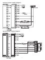
3
common power supply diagram:
special power supply diagram:

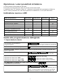
To Reset to Factory Default
a. Disconnect power from the unit
b. Press and hold # key whilst powering the unit back up
c. On hearing two “Di” release # key, system is now back factory settings
NOTE: note only installer data is restored, user data will not be affected
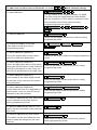
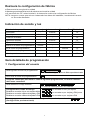
Sound and Light indication
Detailed Programming Guide
1. User Settings
4
Operation Status
Red Light
Green Light
Yellow Light
Buzzer
Power on - Bright - Di
Stand by
Bright
-
-
-
Press keypad - - - Di
Operation successful
-
Bright
-
Di
Operation failed - - - DiDiDi
Enter into programming mode Bright - -
In the programming mode - - Bright Di
Exit from the programming mode
Bright
-
-
Di
Open the door
-
Bright
-
Di
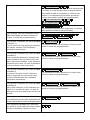
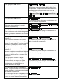
To enter the programming mode * Master code #
999999 is the default factory master code
To exit from the programming mode *
Note that to undertake the following programming the master user must be logged in
To change the master code 0 New code New code# #
The master code can be 6 to 8 digits long
Setting the working mode:
Set valid card only users
Set valid card and PIN users
Set valid card or PIN users
Entry is by card only
Entry is by card and PIN together
Entry is by either card or PIN (default)
3 0 #
3 1 #
3 2 #

5
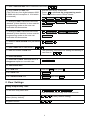
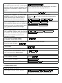
To delete a PIN user 2 User ID number #
To change the PIN of a PIN user
(This step must be done out of
programming mode)
*
ID
number # Old PIN # New PIN #
New PIN #
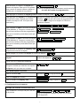
To add a card user (Method 1)
This is the fastest way to enter cards,
user ID number auto generation.
To add a card user (Method 2)
This is the alternative way to enter cards
using User ID Allocation. In this method a
User ID is allocated to a card. Only one
user ID can be allocated to a single card.
To add a card user (Method 3)
Card number is the last 8 digits printed
on the back of the card,user ID number
auto generation
To add a card user (Method 4)
In this method a User ID is allocated to a
card number. Only one user ID can be
allocated to the card number
To delete a card user by card. Note users
can be deleted continuously without
exiting programming mode
To delete a card user by user ID. This
option can be used when a user has lost
their card
To delete a card user by card number.
This option can be used when the user
want to make the change but the card
has lost
Cards can be added continuous exiting programming
mode
1 Read card #
User can be added continuously without exiting
programming mode
1 ID number # Read card #
User can be added continuously without exiting
programming mode
Note users can be deleted continuously without
exiting programming mode
User can be added continuously without exiting
programming mode
1 Card number #
1 ID number. # Card number. #
2 Read Card #
To add a user in either card or PIN mode, i.e. in the mode. (Default setting)3 2 #
To add a Pin user 1 User ID number PIN# #
1 User ID no 1 PIN# # User ID no 2 #
PIN #
The ID number is any number between 1 & 2000.
The PIN is any four digits between 0000 & 9999
with the exception of 1234 which is reserved. Users
can be added continuously without exiting
programming mode as follows:
Users can be deleted continuously without exiting
programming mode
2 User ID #
2 Card number #

To Add a card and PIN user
(The PIN is any four digits between 0000
& 9999 with the exception of 1234 which
is reserved.)
To change a PIN in card and PIN mode
(Method 1) Note that this is done outside
programming mode so the user can
undertake this themselves
To change a PIN in card and PIN mode
(Method 2) Note that this is done outside
programming mode so the user can
undertake this themselves
To delete a Card and PIN user just delete
the card
Normal status: No keypad lockout or
alarm (factory default) 7 0 # (Factory default setting)
Keypad Lockout 7 1 #
To set door relay strike time Master code # 4 0~99 # *
*
0-99 is to set the door relay time 0-99 seconds
6
To add a card and PIN user in card and PIN mode ( )
Add the card as for a card user
Press to exit from the programming mode
Then allocate the card a PIN as follows:
The operating is the same as adding and deleting a
card user in
*
*Read card 1234 # PIN # PIN #
*Read Card Old PIN # New PIN #
New PIN #
*ID number # New PIN #Old PIN #
New PIN #
2 User ID #
To Add and Delete a card user
2 0000 #
To unlock thedoor
For a PIN user Enter the PIN then press #
For a card User Read card
For a card and PIN user Read card then enter PIN #
1 #3
To add a card user in card mode ( )
0 #3
2 #3
To delete ALL users. Note that this is a
dangerous option so use with care
To delete All users
Relay Output Delay Time
2. Door Settings

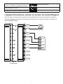
The unit operating as a Wigeand Output Reader
In this mode the unit supports a Wiegand 26 bit output so the Wiegand data lines can be
connected to any controller which supports a Wiegand 26 bit input.
7

8
RF ENERGY EXPOSURE AND PRODUCT SAFETY GUIDE
Before using this radio, read this guide which cont-ains important operating
instructions for safe usage and RF energy awareness and control for compliance
with applicable standards and regulations.
This radio uses electromagnetic energy in the radio frequency (RF) spectrum to provide
communications between two or more users over a distance. RF energy, which when used
improperly, can cause biological damage.
All Retekess radios are designed, manufactured, and tested to ensure they meet
government-established RF exposure levels. In addition, manufacturers also recommend specific
operating instructions to users of the radios. These instructions are important because they inform
users about RF energy exposure and provide simple procedures on how to control it.
Please refer to the following websites for more information on what RF
energy exposure is and how to control your exposure to assure compliance with established RF
exposure limits: http://www.who.int/en/
Local Government Regulations
When radios are used as a consequence of employment, the Local Government Regulations
requires users to be fully aware of and able to control their exposure to meet occupational
requirements. Exposure awareness can be facilitated by the use of a product label directing users to
specific user awareness information. Your Retekess radio has
a RF Exposure Product Label. Also, your Retekess user manual, or separate safety booklet includes
information and operating instructions required to control your RF exposure and to satisfy
compliance requirements.
Radio License (if appropriate)
Governments keep the radios in classification, business radios operate on radio
frequencies that are regulated by the local radio management departments (FCC, ISED, OFCOM,
ANFR, BFTK, Bundesnetzagentur...).To transmit on these frequencies, you are required to have a
license issued by them. The detailed classification and the use of your radios, please contact the
local government radio management departments. Use of this radio outside the country where it was
intended to be distributed is subject to government regulations and may be prohibited.
Unauthorized modification and adjustment
Changes or modifications not expressly approved by the party respon-sible for compliance may void
the user’s authority granted by the local government radio management departments to operate this
radio and should not be made. To comply with the corresponding requirements, transmitter
adjustments should be made only by or under the supervi-sion of a person certified as technically
qualified to perform transmitter maintenance and repairs in the private land mobile and fixed
services
as certified by an organization representative of the user of those services.Replacement of any
transmitter component (crystal, semiconductor, etc.) not authorized by the local government radio
management depa-rtments equipment authorization for this radio could violate the rules.
FCC Requirements:
• This device complies with part 15 of the FCC Rules. Operation is subject to the following two
conditions:
(1) This device may not cause harmful interference, and
(2) this device must accept any interference received, including interference that may cause
undesired operation
• This equipment has been tested and found to comply with the limits for a Class B digital device,
pursuant to Part 15 of the FCC Rules. These limits are designed to provide reasonable protection
against harmful interference in a residential installation.This equipment generates uses and can
radiate radio frequency energy and, if not installed and used in accordance with the instructions, may
cause harmful interference to radio communications. However, there is no guarantee that

8
interference will not occur in a particular installation. If this equipment does cause
harmful interference to radio or television reception, which can be determined by turning the
equipment off and on, the user is encouraged to try to correct the interference by one or more of the
following measures:
- Reorient or relocate the receiving antenna.
- Increase the separation between the equipment and receiver.
- Connect the equipment into an outlet on a circuit different from that to which the receiver is
connected.
- Consult the dealer or an experienced radio/TV technician for help.
CE Requirements:
• (Simple EU declaration of conformity) Henan Eshow Electronic Commerce Co.,Ltd declares that
the radio equipment type is in compliance with the essential requirements and other relevant
provisions of RED Directive 2014/53/EU and the ROHS Directive 2011/65/EU and
the WEEE Directive 2012/19/EU; the full text of the EU declaration of conformity is
available at the following internet address:
www.retekess.com.
• Disposal
The crossed-out wheeled-bin symbol on your product, litera-ture, or packaging reminds you that in
the European Union, all electrical and electronic products, batteries, and accumu-lators
(rechargeable batteries) must be taken to designated collection locations at the end of their working
life. Do not dispose of these products as unsorted municipal waste. Dispose of them according to the
laws in your area.
IC Requirements:
Licence-exempt radio apparatus This device contains licence-exempt transmitter(s)/receiver(s) that
comply with Innovation, Science and Economic Development Canada’s licence-exempt RSS(s).
Operation is subject to the following two conditions:
(1) This device may not cause interference.
(2) This device must accept any interference, including interference that may cause undesired
operation of the device. Le présent appareil est conforme aux CNR d’Industrie Canada applicables
aux appareils radio exempts de licence. L’exploitation est autorisée aux deux conditions suivantes :
(1) l’appareil ne doit pas produire de brouillage;
(2) l’utilisateur de l’appareil doit accepter tout brouillage radioélectrique subi, même si le brouillage
est susceptible d’en compromettre le fonctionnement.
RF Exposure Information
• DO NOT operate the radio without a proper antenna attached, as this may damage the radio and
may also cause you to exceed RF expos-ure limits. A proper antenna is the antenna supplied with
this
radio by the manufacturer or an antenna specifically authorized by the manuf-acturer for use with this
radio, and the antenna gain shall not exceed the specified gain by the manufacturer declared.
• DO NOT transmit for more than 50% of total radio use time, more than 50% of the time can cause
RF exposure compliance requirements to be exceeded.
• During transmissions, your radio generates RF energy that can possibly cause interference with
other devices or systems. To avoid such interference, turn off the radio in areas where signs are
posted to do so.
• The device complies with RF specifications when the device used at 5mm from your body.
Third-party belt-clips, holsters, and similar acc-essories used by this device should not contain any
metallic compon-ents. Body-worn accessories that do not meet these requirements may not comply
with RF
exposure requirements and should be avoided.
• DO NOT operate the transmitter in areas that are sensitive to electromagnetic radiation such as
hospitals, aircraft, and blasting sites.
Avoid Choking Hazard
Small Parts. Not for children under 3 years.

8
Protect your hearing
• Use the lowest volume necessary to do your job.
• Turn up the volume only if you are in noisy surroundings.
• Turn down the volume before adding headset or earpiece.
• Limit the amount of time you use headsets or earpieces at high volume.
• When using the radio without a headset or earpiece, do not place the radio's speaker
directly against your ear
• Use careful with the earphone maybe possible excessive sound pressure from
earphones and headphones can cause hearing loss Note: Exposure to loud noises from
any source for exten-ded periods of time may temporarily or permanently affect your
hearing. The louder the radio's volume, the less time
is required before your hearing could be affected. Hearing damage from loud noise is
sometimes undetectable at first and can have a cumulative effect.
Antennas
• Do not use any portable radio that has a damaged antenna. If a damaged antenna
comes into contact with the skin when the radio is in use, a minor burn can result.
Batteries (If appropriate)
• When the conductive material such as jewelry, keys or chains touch exposed
terminals of the batteries, may complete an electrical circuit (short circuit the battery)
and become hot to cause bodily injury such as burns.Exercise care in handling any
battery, particularly when placing it inside a pocket, purse or other container with metal
objects Long transmission
• When the transceiver is used for long transmissions, the radiator and chassis will
become hot.
Forbid
• Do not use charger outdoors or in moist environments, use only in dry
locations/conditions.
• Do not disassemble the charger, that may result in risk
of electrical shock or fire.
• Do not operate the charger if it has been broken o damaged in any way.
• Do not place a portable radio in the area over an air bagor in the air bag deployment
area. The radio may be propelled with great force and cause serious injury to occupants
of the vehicle when the air bag inflates.
To reduce risk
• Pull by the plug rather than the cord when disconnecting the charger.
• Unplug the charger from the AC outlet before attempting any maintenance or cleaning.
• Contact Retekess for assistance regarding repairs and service.
• The adapter shall be installed near the equipment and shall be easily accessible
• Risk of explosion if battery is replaced by an incorrect type. Dispose of used batteries
according to the instructions.
• Adapter shall be installed near the equipment and shall be easily accessible.
• The plug considered as disconnect device of adapter.
• The operating temperature of the EUT can’t exceed the specified range.
• This radio meets the RF exposure guidelines when used with the Retekess accessories
supplied or designated for the product. Use of other accessories may not ensure
compliance with the RF exposure guidelines and may violate regulations.
• For a list of Retekess-approved accessories for your radio model, visit the following
website:http://www.Retekess.com
WARNING
WARNING
WARNING
WARNING
Avoid Burns
Safety Operation
Approved Accessories

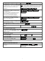
Betriebsspannung DC 12V±10%
Benutzerkapazität
2000
Kartenlesedistanz
3-6 cm
Aktiver Strom <60mA
Leerlaufstrom
25±5 mA
Ausgangslast sperren
Max 3A
Betriebstemperatur -45℃~60℃
Betriebsfeuchtigkeit
10%- 90% RH
Wasserdicht
Einstellbare Türrelaiszeit 0 -99 seconds
Wiegand-Schnittstelle
Wiegand 26-bit
Anschlüsse Eletrisches Schloß, Exit Button, External Alarm,External
reader
Gemäß IP68
1
Beschreibung
Eigenschaften
• Wasserdicht, IP68-konform.
• Gehäuse aus Zink-Aluminium-Legierung, sehr stabil .
• Komplette Programmierung über Tastatur möglich.
• Bis zu 2000 Personen unterstützt diese Karte, PIN, Karte + PIN.
• Kann auch als eigenständige Tastatur verwendet werden.
• Hintergrundbeleuchtung der Tasten.
• Wiegand 26- Bit Eingang zum Anschluss an externen Antrieb
• Wiegand 26 -Bit Ausgang zum Anschluss an einen Controller.
• Türschließzeit , Alarmzeit, Türöffnungszeit können eingestellt warden.
• Sehr geringer Stromverbrauch (30mA).
• Reaktionsgeschwindigkeit : < 20ms mit 2000 Benutzern geprüft.
• Sperrung für den den Ausgangsstromkurzschlussschutz
• Einfach zu installieren und zu programmieren
• Rote, gelbe und grüne LED’s zeigen den Arbeitsstatus an.
Spezifikationen
Das Gerät ist ein multifunktionaler Standalone-Access-Controller für eine Tür oder ein
Wiegand-Ausgabetastenfeld oder Kartenleser. Es eignet sich für den Einbau in geschlossenen
Räumen oder im Freien , in offnener Umgebung. Es ist in einem starken, robusten und
vandalensicheren Zinklegierungs-Gehäuse untergebracht, das entweder in einem hellen Silber
oder Matt Silber-Finish erhältlich ist.Die Elektronik ist vollständig vergossen, daher ist das Gerät
wasserdicht und entspricht IP68.Dieses Gerät unterstützt bis zu 2000 Benutzer mit einer Karte,
einer 4-stelligen PIN oder einer Karte + PIN.Der eingebaute Kartenleser unterstützt 125 kHz
EM-Karten. Das Gerät verfügt über viele zusätzliche Funktionen , wie Kurzschlussschutz,Wiegand
Ausgabe und eine Tastatur mit Hintergrundbeleuchtung.
Deutsch

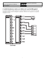
Farbe Funktion Beschreibung
Rosa BELL_A Türklingelknopf ein Ende
Hellblaue BELL_B Türklingel zum anderen Ende
Grün D0 WG Ausgang D0
Weiß D1 WG Ausgang D1
Gelb OPEN Exit-Taste ein Ende (das andere Ende verbunden GND)
Rot 12V+ 12V + DC Geregelte Stromversorgung
Schwarz GND 12V - Gleichspannungseingang
Blaues NO Relais-Einschalt-Endschalter (Schließen Sie die positive
elektrische Verriegelung "-" an)
Lila COM Relais Öffentliches Ende, GND verbinden
Orange NC Relais Geschlossenes Ende (negatives elektrisches Schloss
anschließen "-")
2
Paketdetails
Name
Menge
Spezifikationen
Tastenfeld
1
Benutzerhandbuch
1
Schraubendreher 1Φ20mm×60mm,Speziell für die Tastatur
Gummistopfen
2
Φ6mm×30 mm, zur Befestigung verwendet
Blechschrauben
2
Φ4mm×28 mm, zur Befestigung verwendet
Torx 1Φ3mm×6mm, zur Befestigung verwendet
Der tatsächliche Inhalt des Pakets unterliegt der Werbung.
Installation
• Entfernen Sie bitte die hintere Abdeckung von der Tastatur , mit dem mitgelieferten
Spezialschraubendreher
• Bohren Sie zwei Löcher in die Wand , für die selbstschneidenden Schrauben und ein Loch für
das Kabel
• Legen Sie den mitgelieferten Gummistopfen in
die beiden Löcher
• Befestigen Sie die hintere Abdeckung mit 2
selbstschneidenden Schrauben fest an der
Wand
• Führen Sie das Kabel durch die Kabelöffnung
• Schließen Sie die Tastatur an die hintere
Abdeckung an
Verkabelung

Spezelles stromversorgungsdiagramm
Gemeisames Stromversorgungsdiagramm
3

4
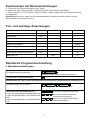
Betriebsstatus Rot Licht Grün Licht
anschalten -Hell
Bereithalten Hell -
Drücken Sie die Tastatur - -
Operation erfolgreich -Hell
Operation scheitern - -
Eintreten Programmiermodus Hell -
Im Programmiermodus - -
Zurücktreten Programmiermodus Hell -
Öffne die Tür -Hell -
Gelb Licht Summpfeife
- Di
- -
- Di
- Di
- DiDiDi
-
Hell Di
- Di
Di
Zurücksetzen auf Werkseinstellungen
a. Trennen Sie die Stromversorgung vom Gerät
b. Halten Sie die # Taste gedrückt, während Sie das Gerät wieder einschalten
C. Wenn Sie zwei "Di"-Töne hören, lösen # Tasten, ist das System jetzt auf Werkseinstellung
zurückgesetzt.
Hinweis:Beachten Sie, dass nur die Installationsdaten wiederhergestellt werden und die
Benutzerdaten nicht betroffen sind
Ton- und wichtige Anweisungen
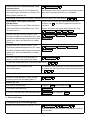
Detaillierte Programmieranleitung
1. Benutzereinstellungen
Programmiermodus eintreten * Hauptcode #
999999 ist das Werkseinstellung Passwort
Zurücktreten Programmiermodus *
Bitte beachten Sie, dass sich der Hauptbenutzer für die folgende Programmierung anmelden muss
Um den Hauptcode zu ändern 0 neuer Code # #
neuer Code
Der Hauptcode kann 6-8 Ziffern haben
Stellen Sie den Arbeitsmodus ein:
Legen Sie einen gültigen Kartenbenutzer fest
Legen Sie gültige Karten- und PIN-Benutzer
fest
Legen Sie gültige Karten- oder PIN-Benutzer
fest
Nur durch die Karte zu betreten !
Nur durch die Karte und PIN,
zusammen zu betreten !
Nur durch die Karte oder PIN zu
betreten(Standard) !
3 0
3 1
3 2 #
#
#

5
PIN-Benutzer löschen 2 Benutzer Nummer #
Benutzer können fortlaufend löschen, ohne das
Programm zu verlassen
Das PIN Benutzer möchte PIN ändern
(Dieser Schritt muss beim Verlassen des
Programmiermodus ausgeführt werden)
Um einen Kartenbenutzer hinzuzufügen
(Methode 1) 1 Karte lesen #
Die Karte kann kontinuierlich hinzugefügt werden,
ohne den Programmiermodus zu verlassen
Um einen Kartenbenutzer hinzuzufügen
(Methode 2)
Dies ist eine alternative Möglichkeit,
Eingabekarten mit Benutzerkennungen
zu versehen. Bei dieser Methode wird die
Benutzer-ID einer Karte zugewiesen. Nur
eine Benutzer-ID kann einer Karte
zugewiesen werden.
1 ID Nummer # Karte lesen #
Der Benutzer kann kontinuierlich hinzugefügt werden,
ohne den Programmiermodus zu verlassen
Um eine n Kartenbenutzer hinzuzufügen
(Methode 3)
Die Kartennummer ist die letzte 8 Ziffern
auf der Rückseite der Karte, die
Benutzer-ID-Nummer Automatisch generiert.
1 Karte Nummer #
Der Benutzer kann kontinuierlich hinzugefügt werden,
ohne den Programmiermodus zu verlassen
Um einen Kartenbenutzer hinzuzufügen
(Methode 4)
Bei dieser Methode wird die Benutzer-ID
einer Karte zugewiesen.Nur eine Benutzer-ID
kann einer Karte zugewiesen werden.
1 ID number. # Card number. #
Der Benutzer kann kontinuierlich hinzugefügt werden,
ohne den Programmiermodus zu verlassen
Einen Kartennutzer nach Karte löschen
Benutzer können direkt gelöscht werden,
ohne den Programmiermodus zu verlassen
2 Karte lesen #
Um einen Benutzer im Karten- oder PIN-Modus hinzuzufügen, Z.B Im Modus
(Standardeinstellung)
3 2 #
Um einen Pin-Benutzer hinzuzufügen
* ID Nummer Alte PIN Neue PIN# ##
Neue PIN #
1Benutzer-ID Nr. 1 # PIN # Benutzer-ID Nr. 2
# PIN #
1 Benutzer-ID-Nummer # PIN #
Die ID-Nummer ist eine beliebige Zahl zwischen 1 und
2000.Die PIN besteht aus vier Ziffern zwischen 0000
und 9999 mit Ausnahme von 1234, die reserviert ist.
Benutzer können kontinuierlich hinzugefügt werden,
ohne zu beenden Programmiermodus wie folgt:
Löschen von Kartenbenutzern nach
Benutzer-ID
Diese Methode kann verwendet werden,
wenn der Benutzer seine Karte verliert
2 Benutzer-ID #

2. Türeinstellungen
Verzögerung des Relaisausgangs
Stellen Sie die bestreikene Zeit der Tür ein *Master-Code # 4 0~99 # *
0-99 dient zum Einstellen der Türrelaiszeit von 0 bis
99 Sekunden
6
Hinzufügen einer Karte und eines
PIN-Benutzer
Die PIN besteht aus vier Ziffern zwischen
0000 und 9999 mit Ausnahme von 1234,
die reserviert ist.
Ändern Sie die PIN im Karten- und
PIN-Modus(Methode1) Beachten Sie, dass
dies beim Verlassen des Programmiermodus
getan wird, damit der Benutzer es selbst
tun kann
Ändern Sie die PIN im Karten- und
PIN-Modus(Methode2)Beachten Sie, dass
dies beim Verlassen des Programmiermodus
getan wird, damit der Benutzer es selbst
tun kann
* ID nummer # Alte PIN # Neue PIN #
Neue PIN #
Karte lesen* Alte PIN # Neue PIN #
Neue PIN #
Um einen Karten-und PIN-Benutzer zu
löschen, löschen Sie einfach die Karte
Fügen Sie Kartenbenutzer im Kartenmodus hinzu( )
3 0 #
Hinzufügen und Löschen eines
Kartenbenutzers
Die Methode zum Entfernen eines Kartenbenutzers
ist gleiche wie das Hinzufügen eines Kartenbenutzers
im
Löschen Sie alle Benutzer
Löschen Sie alle Benutzer :Seien Sie bitte
vorsichtig, bevor Sie den Befehl geben ! !
2 0000 #
Öffnen die Tür
Für einen PIN-Benutzer Eingeben dann drücken Sie
PIN #
Für einen Karte Benutzer
Für einen PIN-Benutzer und Karte Benutzer und eingeben PIN #Karte lesen
Karte lesen
Löschen Sie den Kartenbenutzer nach
Kartennummer.
Diese Methode eignet sich für Benutzer,
die Änderungen vornehmen möchten, die
Karte jedoch verloren ist
2 Karte nummer #
Der Benutzer kann kontinuierlich hinzugefügt werden,
ohne den Programmiermodus zu verlassen
Hinzufügen einer Karte und eines PIN-Benutzer im Karten und PIN Modus( )
1 #3
* 1234 # PIN # PIN #
Karte lesen
Fügen Sie eine Karte als Kartenbenutzer hinzu
Drücken Sie , um den Programmiermodus zu
verlassen
Weisen Sie dann der Karte eine PIN zu,wie folgt
*
2 #3
Benutzer ID #2

Das Gerät arbeitet als Wigeand-Ausgabegerät
In diesem Modus unterstützt das Gerät den Wiegand 26-Bit-Ausgang, so dass das
Wiegand-Datenkabel an jeden beliebigen Controller angeschlossen werden kann, der
Wiegands 26-Bit-Eingang unterstützt.
7
Normaler Zustand: keine Tastatursperre
oder Alarm (Werkseinstellung)
7 0 # (Werkseinstellung)
Tastatursperre 7 1 #

8
8
RF ENERGIE EXPOSURE UND PRODUKTSICHERHEIT
Lesen Sie vor der Verwendung dieses Geräts diese
Bedienungsanleitung, die wichtige Betriebsanleitungen für
den sicheren Gebrauch und die Kenntnis der Funkfrequenz
Dieses Gerät verwendet elektromagnetische Energie im Radiofrequenzspektrum (RF), um die
Kommunikation zwischen zwei oder mehr Benutzern über eine Distanz hinweg bereitzustellen.
RF-Energie, die bei unsachgemäßer Verwendung biologische Schäden verursachen kann.
Alle Retekess-Funkgeräte werden entwickelt, hergestellt und getestet, um sicherzustellen, dass sie
den von der Regierung festgelegten RF-Expositionswerten entsprechen. Darüber hinaus
empfehlen Hersteller den Benutzern der Funkgeräte auch spezifische Bedienungsanleitungen.
Diese Anweisungen sind wichtig, da sie die Benutzer über die Einwirkung von RF-Energie
informieren und einfache Verfahren für deren Steuerung enthalten.
Auf den folgenden Websites finden Sie weitere Informationen zu RF-Energieexpositionen und zur
Kontrolle Ihrer Exposition, um die Einhaltung der festgelegten RF-Expositionsgrenzwerte
sicherzustellen: http://www.who.int/de/
Lokale Regierungsbestimmungen
Wenn Funkgeräte als Folge einer Beschäftigung verwendet werden, müssen die Benutzer nach
den örtlichen Regierungsvorschriften ihre Exposition genau kennen und kontrollieren können, um
den beruflichen Anforderungen zu genügen. Die Erkennung der Exposition kann durch die
Verwendung eines Produktetiketts erleichtert werden, das die Benutzer zu bestimmten
Benutzerinformationen führt. Ihr Retekess-Funkgerät verfügt über ein RF-Exposure-Produktetikett.
Außerdem enthält Ihr Retekess-Benutzerhandbuch oder eine separate Sicherheitsbroschüre
Informationen und Betriebsanleitungen, die zur Kontrolle der RF-Belastung und zur Einhaltung der
Konformitätsanforderungen erforderlich sind.
Radio-Lizenz (falls zutreffend)
Die Regierungen halten die Funkgeräte in der Klassifizierung, die Geschäftsradios arbeiten mit
Funkfrequenzen, die von den lokalen Funkverwaltungsabteilungen (FCC, ISED, BAKOM, ANFR,
BFTK, Bundesnetzagentur ...) reguliert werden. Um auf diesen Frequenzen übertragen zu können,
benötigen Sie eine Lizenz. Die genaue Klassifizierung und Verwendung Ihrer Funkgeräte erfahren
Sie bei den zuständigen Verwaltungsstellen der örtlichen Behörden.
Die Verwendung dieses Radios außerhalb des Landes, in dem es verteilt werden soll, unterliegt
den gesetzlichen Bestimmungen und kann verboten werden.
Eigenmächtige Änderung und Einstellung
Änderungen oder Modifikationen, die nicht ausdrücklich von der für die Einhaltung der
Bestimmungen verantwortlichen Partei genehmigt wurden, können die Berechtigung des
Benutzers, die von den lokalen
Funkverwaltungsabteilungen für den Betrieb dieses Funkgeräts erteilt wurde, aufheben und sollten
nicht
vorgenommen werden. Um die entsprechenden Anforderungen zu erfüllen, sollten die
Einstellungen des Senders nur von oder unter der Aufsicht einer Person vorgenommen werden,
die als technisch qualifiziert für die Wartung und Reparatur des Senders in privaten Landfunk- und
Festnetzdiensten zertifiziert ist und von einer Organisation, die dessen Nutzer vertritt, zertifiziert ist
Dienstleistungen.
Der Austausch von Senderkomponenten (Quarz, Halbleiter usw.), die nicht durch die Autorisierung
des Funkmanagements der örtlichen Behörden autorisiert wurden, könnte gegen die Regeln
verstoßen.
FCC-Anforderungen:
• Dieses Gerät entspricht Abschnitt 15 der FCC-Bestimmungen. Der Betrieb unterliegt den
folgenden zwei Bedingungen:
(1) Dieses Gerät darf keine schädlichen Interferenzen verursachen
(2) Dieses Gerät muss alle empfangenen Interferenzen akzeptieren, einschließlich Interferenzen,
La pagina si sta caricando...
La pagina si sta caricando...
La pagina si sta caricando...
La pagina si sta caricando...
La pagina si sta caricando...
La pagina si sta caricando...
La pagina si sta caricando...
La pagina si sta caricando...
La pagina si sta caricando...
La pagina si sta caricando...
La pagina si sta caricando...
La pagina si sta caricando...
La pagina si sta caricando...
La pagina si sta caricando...
La pagina si sta caricando...
La pagina si sta caricando...
La pagina si sta caricando...
La pagina si sta caricando...
La pagina si sta caricando...
La pagina si sta caricando...
La pagina si sta caricando...
La pagina si sta caricando...
La pagina si sta caricando...
La pagina si sta caricando...
La pagina si sta caricando...
La pagina si sta caricando...
La pagina si sta caricando...
La pagina si sta caricando...
La pagina si sta caricando...
La pagina si sta caricando...
La pagina si sta caricando...
La pagina si sta caricando...
La pagina si sta caricando...
La pagina si sta caricando...
La pagina si sta caricando...
La pagina si sta caricando...
La pagina si sta caricando...
-
 1
1
-
 2
2
-
 3
3
-
 4
4
-
 5
5
-
 6
6
-
 7
7
-
 8
8
-
 9
9
-
 10
10
-
 11
11
-
 12
12
-
 13
13
-
 14
14
-
 15
15
-
 16
16
-
 17
17
-
 18
18
-
 19
19
-
 20
20
-
 21
21
-
 22
22
-
 23
23
-
 24
24
-
 25
25
-
 26
26
-
 27
27
-
 28
28
-
 29
29
-
 30
30
-
 31
31
-
 32
32
-
 33
33
-
 34
34
-
 35
35
-
 36
36
-
 37
37
-
 38
38
-
 39
39
-
 40
40
-
 41
41
-
 42
42
-
 43
43
-
 44
44
-
 45
45
-
 46
46
-
 47
47
-
 48
48
-
 49
49
-
 50
50
-
 51
51
-
 52
52
-
 53
53
-
 54
54
-
 55
55
-
 56
56
-
 57
57


Retekess T-AC04 Metal Standalone Keypad Access Control Manuale utente
- Tipo
- Manuale utente
- Questo manuale è adatto anche per
in altre lingue
- English: Retekess T-AC04 Metal Standalone Keypad Access Control User manual
- français: Retekess T-AC04 Metal Standalone Keypad Access Control Manuel utilisateur
- español: Retekess T-AC04 Metal Standalone Keypad Access Control Manual de usuario
- Deutsch: Retekess T-AC04 Metal Standalone Keypad Access Control Benutzerhandbuch
Documenti correlati


Altri documenti
-
Crow RUNNER 8/64 Guida d'installazione
-
PRASTEL EASYBKW and EASYKW Manuale del proprietario
-
-
Rosslare AY-B9250BT Manuale utente
-
Motorola SDC1000 Istruzioni per l'uso
-
Comelit SKR Technical Manual
-
Axis A1001 Manuale utente
-
-
GE ATS1192 Manuale del proprietario
-