RCF SUB 9007-AS Active High Power Subwoofers Manuale del proprietario
- Tipo
- Manuale del proprietario

OWNER MANUAL
SUB 9007-AS
SUB 9006-AS
SUB 9004-AS
ACTIVE
HIGH POWER
SUBWOOFERS

.

3
ENGLISH
ITALIANO
LANGUAGE
4
11

4
ENGLISH
1. All the precautions, in particular the safety ones, must be read with special attention, as
they provide important information.
2. Power supply from mains
a. The mains voltage is sufficiently high to involve a risk of electrocution; install and
connect this product before plugging it in.
b. Before powering up, make sure that all the connections have been made correctly and
the voltage of your mains corresponds to the voltage shown on the rating plate on the
unit, if not, please contact your RCF dealer.
c. The metallic parts of the unit are earthed through the power cable. An apparatus with
CLASS I construction shall be connected to a mains socket outlet with a protective
earthing connection.
d. Protect the power cable from damage; make sure it is positioned in a way that it
cannot be stepped on or crushed by objects.
e. To prevent the risk of electric shock, never open this product: there are no parts inside
that the user needs to access.
3. Make sure that no objects or liquids can get into this product, as this may cause a short
circuit.
This apparatus shall not be exposed to dripping or splashing. No objects filled with liquid,
such as vases, shall be placed on this apparatus. No naked sources (such as lighted candles)
should be placed on this apparatus.
4. Never attempt to carry out any operations, modifications or repairs that are not expressly
described in this manual.
Contact your authorized service centre or qualified personnel should any of the following
occur:
- the product does not function (or functions in an anomalous way).
- The power cable has been damaged.
- Objects or liquids have got in the unit.
- The product has been subject to a heavy impact.
5. If this product is not used for a long period, disconnect the power cable.
6. If this product begins emitting any strange odours or smoke, switch it off immediately
and disconnect the power cable.
7. Do not connect this product to any equipment or accessories not foreseen.
For suspended installation, only use the dedicated anchoring points and do not try to hang
this product by using elements that are unsuitable or not specific for this purpose. Also
check the suitability of the support surface to which the product is anchored (wall, ceiling,
structure, etc.), and the components used for attachment (screw anchors, screws, brackets
not supplied by RCF etc.), which must guarantee the security of the system / installation
over time, also considering, for example, the mechanical vibrations normally generated by
transducers.
To prevent the risk of falling equipment, do not stack multiple units of this product unless
this possibility is specified in the user manual.
8. RCF S.p.A. strongly recommends this product is only installed by professional
qualified installers (or specialised firms) who can ensure correct installation
and certify it according to the regulations in force.
The entire audio system must comply with the current standards and regulations
regarding electrical systems.
9. Supports and trolleys.
The equipment should be only used on trolleys or supports, where necessary, that are
recommended by the manufacturer. The equipment / support / trolley assembly must be
SAFETY
PRECAUTIONS
IMPORTANT

5
ENGLISH
moved with extreme caution. Sudden stops, excessive pushing force and uneven floors may
cause the assembly to overturn.
10. There are numerous mechanical and electrical factors to be considered when installing
a professional audio system (in addition to those which are strictly acoustic, such as sound
pressure, angles of coverage, frequency response, etc.).
11. Hearing loss.
Exposure to high sound levels can cause permanent hearing loss. The acoustic pressure level
that leads to hearing loss is different from person to person and depends on the duration
of exposure. To prevent potentially dangerous exposure to high levels of acoustic pressure,
anyone who is exposed to these levels should use adequate protection devices. When a
transducer capable of producing high sound levels is being used, it is therefore necessary
to wear ear plugs or protective earphones. See the manual technical specifications to know
the maximum sound pressure level.
IMPORTANT NOTES
To prevent the occurrence of noise on line signal cables, use screened cables only and avoid
putting them close to:
- Equipment that produces high-intensity electromagnetic fields.
- Power cables.
- Loudspeaker lines.
OPERATING PRECAUTIONS
- Place this product far from any heat sources and always ensure an adequate
air circulation around it.
- Do not overload this product for a long time.
- Never force the control elements (keys, knobs, etc.).
- Do not use solvents, alcohol, benzene or other volatile substances for cleaning
the external parts of this product.
IMPORTANT NOTES
Before connecting and using this product, please read this instruction manual carefully and
keep it on hand for future reference. The manual is to be considered an integral part of
this product and must accompany it when it changes ownership as a reference for correct
installation and use as well as for the safety precautions. RCF S.p.A. will not assume any
responsibility for the incorrect installation and / or use of this product.
WARNING: to prevent the risk of fire or electric shock, never expose this product to rain
or humidity.
OPERATING
PRECAUTIONS
IMPORTANT NOTES
IMPORTANT NOTES
WARNING

6
ENGLISH
COMPONENTS
SUB SERIES
AMPLIFIERS
CABINETS
RCF always has the performer’s needs at the forefront of the design in order to create new lines
of speakers with renewed features, improved sound clarity and definition and even lighter weight
systems.
Every detail of the Sub Series has been carefully studied in order to offer musicians and professionals
the perfect tool to amplify their performance, night after night.
High quality materials, precise manufacturing, careful assembly and extensive quality control
procedures complete the ground-breaking design work of the RCF R&D team.
All transducers are precision built taking advantage of RCF’s superior moulding, assembly
technologies and a wealth of professional knowledge and experience dedicated to achieving
extremely high standards.
All the transducers in Sub Series speakers feature high power magnets in order to guarantee the
best performance and power handling.
Sub Series Subwoofers are equipped with a new generation of Digital Amplifiers. The result of this
is very high output, extremely low distortion and an incredible natural sound.
The amplifier features a solid mechanical aluminium structure that not only stabilize the amplifier
during transportation but also assist in the heat dissipation.
The input section provides:
- In/Out XLR connector
- Crossover Output XLR connector
- System sensitivity control
- Multiple crossover set-up
- Delay set-up
- Cardioid set-up
- 3 status LEDs
The SUB 9007-AS, SUB 9006-AS power amplifier features:
- 2 x 3600 Watt Digital amplifier modules
- Powercon AC input connector
- Vibrostop floating aluminum panel
The SUB 9004-AS power amplifier features:
- 2800 Watt Digital amplifier module
- Powercon AC input connector
- Vibrostop floating aluminum panel
The Sub Series Subwoofer cabinets are built in birch plywood and are designed to dampen down
vibrations even at maximum volume settings. The reflex porting has been resized to offer a better
efficiency. The cabinets are equipped with ergonomically designed forged aluminium handles with
rubber handgrip.
PRODUCT
INFORMATIONS

7
ENGLISH
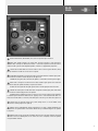
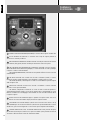
REAR
PANEL
FEMALE XLR INPUTS (BAL/UNBAL). The system accept XLR input connectors.
MALE XLR SIGNAL OUTPUT. The output XLR connector provides a loop through for
speakers daisy chaining. The balanced connector is connected in parallel and can be used to
send the audio signal to other amplified speakers, recorders or supplementary amplifiers.
SYSTEM SET UP ENCODER. Push the encoder to select a function (gain reduction, delay,
preset). Rotate the encoder to select a value or a preset.
GAIN REDUCTION LED. Pushing the encoder once the gain reduction indicator lights green.
Then rotate the encoder to reduce the gain to the right level.
POWER LED. This green led is ON when the speaker is connected to the main power supply.
DELAY LED. Pushing the encoder twice the delay indicator lights green. Then rotate the
encoder to delay the speaker. The delay is expressed in meters.
SIGNAL LED. The signal indicator lights green if there is audio signal present on the main
PRESET LED. Pushing the encoder three times the preset indicator lights green. Then rotate
the encoder to load the right preset to the speaker.
LIMITER LED. The amplifier has a built in limiter circuit to prevent clipping of the amplifiers
or overdriving the transducers. When the soft clipping circuit is active the LED blinks RED. It is
okay if the limit LED blinks occasionally. If the LED lights continuously, turn down the signal level.
SYSTEM SET UP DISPLAY. Display the system setting values. In case of RDNet active
connection a rotating segment will light up.
RDNET LOCAL SETUP/BYPASS. When released the local setup is loaded and RDNet can
only monitor the speaker. When switched the RDNet setup is loaded and bypass any speaker
local preset.
RDNET IN/OUT PLUG SECTION. The RDNET IN/OUT PLUG SECTION features etherCON
connectors for the RCF RDNet protocol. This allows the user to completely control the speaker
using the RDNet software.
1
2
3
4
5
6
7
8
9
1
2
8
9
7
3
6
45

8
ENGLISH
10
11
WARNING
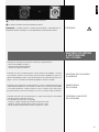
Pushing the rear encoder it is possible to select the following three functions:
- input gain reduction
- speaker delay setting
- selection of a speaker preset
Pushing once the rear encoder the gain reduction LED will light up. Now rotating the
encoder counter clockwise it will be possible to reduce the input gain. The gain reduction
will be in steps of 0,1 dB for the first 10 dB and than in 1 dB steps.
The maximum reduction is 99 dB.
Pushing a second time the rear encoder the delay LED will light up. Now rotating the
encoder clockwise it will be possible to delay the signal output of the speaker.
The delay is expressed in meter. The delay will be in steps of 0,1 m for the first 10 m and
than in 1 m steps. The maximum delay will be 20 meter.
THE REAR ENCODER
CONTROL AND
SPEAKER SETTING
INPUT GAIN REDUCTION
SPEAKER DELAY SETTING
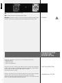
AC INPUT. Powercon locking 3-pole AC mains.
AC OUTPUT. Powercon locking 3-pole AC mains output.
WARNING: the Powercon connector is used to disconnect the system from the power supply
network. It shall be easily accessible after the instillation and during the use of the system.
10 11

9
ENGLISH
Pushing a third time the rear encoder the preset LED will light up. Now rotating the encoder
clockwise it will be possible to select a preset. There are ten presets in four groups:
- INFRA SUBWOOFER (S)
- EXTENDED LOW (L)
- CARDIOID (SC, LC)
- LOW PASS EXCLUDED (SE, LE)
S1. INFRA SUBWOOFER. Linear preset with a 50 Hz low pass. The high pass is set at 20 Hz.
S2. INFRA SUBWOOFER. Linear preset with a 60 Hz low pass. The high pass is set at 20 Hz.
L2. EXTENDED LOW PRESET. Typical subwoofer preset. High pass preset at 30 Hz and Low
pass at 60 Hz.
L3. EXTENDED LOW PRESET. Typical subwoofer preset. High pass preset at 30 Hz and Low
pass at 70 Hz.
L4. EXTENDED LOW PRESET. Typical subwoofer preset. High pass preset at 30 Hz and Low
pass at 80 Hz.
L5. EXTENDED LOW PRESET. Typical subwoofer preset. High pass preset at 30 Hz and Low
pass at 90 Hz.
SC. CARDIOID PRESET. Cardioid Preset to be used in conjunction with S1 – S2 preset.
LC. CARDIOID PRESET. Cardioid Preset to be used in conjunction with L1 – L4 preset.
SE. LOW PASS EXCLUDED. Dedicated preset with 20 Hz High Pass and Low Pass excluded
(moved to 400 Hz)
LE. LOW PASS EXCLUDED. Dedicated preset with 20 Hz High Pass and Low Pass excluded
(moved to 400 Hz)
After the parameter settings the 2 digits display will flash one time. This represent saving
all the preset values in the speaker memory.
Once saved, all the speaker settings are permanent. It is possible to turn off and turn on,
the speaker will remember the last settings.
To reset the speaker to the original settings :
- turn off the speaker
- keep the encoder pressed
- turn on the speaker
- the status yellow led will be blinking slowly, keep the encoder pressed
- the status yellow led will be blinking fast, now release the encoder
- the reset procedure is finished
Using the RDNet IN/OUT connection it is possible to load in the speaker memory a dedicated
user equalisation. The speaker reset procedure will cancel even this equalisation.
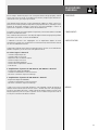
The XLR connectors use the following AES standard:
PIN 1 = GROUND (SHIELD)
PIN 2 = HOT (+)
PIN 3 = COLD (-)
SAVING
A SPEAKER PRESET
SELECTION OF
A SPEAKER PRESET
SPEAKER RESET
HOT GND
BAL. XLR
COLD
CONNECTIONS

10
ENGLISH
At this point you can connect the power supply cable and the signal cable, but before turning
on the speaker make sure that the volume control is at the minimum level (even on the mixer
output). It is important that the mixer is already ON before turning on the speaker. This will avoid
damage to the speakers and noisy “bumps” due to turning on parts on the audio chain. It is a
good practice to always turn on speakers at last and turn them off immediately after the show.
Now you can turn ON the speaker and adjust the volume control to a proper level.
It is possible to create subwoofer cardioid systems using groups of three modules.
A group is made of three modules, the group shall be made as follow:
- 2 modules pointing in forward direction, cardioid switch released;
- 1 module pointing in backward direction, cardioid switch pressed;
- all 3 modules shall have the same settings (system delay, sensitivity, x-low cut, x-over,…).
BEFORE TURNING ON
THE SPEAKER
CARDIOID SET-UP
WARNING: daisy chaining speakers always make sure that the maximum current
requirement does not exceed the maximum admitted POWERCON current. In case of doubt
call the closest RCF SERVICE CENTRE.
INSTALLATION
WARNING
The fuse settings/replacement shall be as follow:
SUB 9006-AS and SUB 9007-AS: FUSE VALUE T 15 A H 250 V
SUB 9004-AS: FUSE VALUE T 8 A H 250 V
SERVICE NOTE
VOLTAGE SETUP
(RESERVED TO THE RCF SERVICE CENTRE)

11
ITALIANO
1. Tutte le avvertenze, in particolare quelle relative alla sicurezza, devono essere lette
con particolare attenzione, in quanto contengono importanti informazioni.
2. Alimentazione diretta da rete
a. La tensione di alimentazione dell’apparecchio ha un valore sufficientemente alto da
costituire un rischio di folgorazione per le persone: non procedere mai all’installazione
o connessione dell’apparecchio con l’alimentazione inserita.
b. Prima di alimentare questo prodotto, assicurarsi che tutte le connessioni siano corrette
e che la tensione della vostra rete di alimentazione corrisponda quella di targa
dell’apparecchio, in caso contrario rivolgetevi ad un rivenditore RCF.
c. Le parti metalliche dell’apparecchio sono collegate a terra tramite il cavo di
alimentazione. Un apparecchio avente costruzione di CLASSE I deve essere connesso
alla presa di rete con un collegamento alla terra di protezione.
d. Accertarsi che il cavo di alimentazione dell’apparecchio non possa essere calpestato o
schiacciato da oggetti, al fine di salvaguardarne la perfetta integrità.
e. Per evitare il rischio di shock elettrici, non aprire mai l’apparecchio: all’interno non vi
sono parti che possono essere utilizzate dall’utente.
3. Impedire che oggetti o liquidi entrino all’interno del prodotto, perché potrebbero causare
un corto circuito. L’apparecchio non deve essere esposto a stillicidio o a spruzzi d’acqua;
nessun oggetto pieno di liquido, quali vasi, deve essere posto sull’apparecchio.
Nessuna sorgente di fiamma nuda (es. candele accese) deve essere posta sull’apparecchio.
4. Non eseguire sul prodotto interventi / modifiche / riparazioni se non quelle espressamente
descritte sul manuale istruzioni.
Contattare centri di assistenza autorizzati o personale altamente qualificato quando:
- l’apparecchio non funziona (o funziona in modo anomalo).
- Il cavo di alimentazione è danneggiato.
- Oggetti o liquidi sono entrati nell’apparecchio.
- L’apparecchio ha subito forti urti.
5. Qualora questo prodotto non sia utilizzato per lunghi periodi, scollegare il cavo
d’alimentazione.
6. Nel caso che dal prodotto provengano odori anomali o fumo, spegnerlo immediatamente
e scollegare il cavo d’alimentazione.
7. Non collegare a questo prodotto altri apparecchi e accessori non previsti.
Quando è prevista l’installazione sospesa, utilizzare solamente gli appositi punti di
ancoraggio e non cercare di appendere questo prodotto tramite elementi non idonei o
previsti allo scopo.
Verificare inoltre l’idoneità del supporto (parete, soffitto, struttura ecc., al quale è ancorato
il prodotto) e dei componenti utilizzati per il fissaggio (tasselli, viti, staffe non fornite da
RCF ecc.) che devono garantire la sicurezza dell’impianto / installazione nel tempo, anche
considerando, ad esempio, vibrazioni meccaniche normalmente generate da un trasduttore.
Per evitare il pericolo di cadute, non sovrapporre fra loro più unità di questo prodotto,
quando questa possibilità non è espressamente contemplata dal manuale istruzioni.
8. La RCF S.p.A. raccomanda vivamente che l’installazione di questo prodotto
sia eseguita solamente da installatori professionali qualificati (oppure da ditte
specializzate) in grado di farla correttamente e certificarla in accordo con le
normative vigenti. Tutto il sistema audio dovrà essere in conformità con le
norme e le leggi vigenti in materia di impianti elettrici.
AVVERTENZE PER
LA SICUREZZA
IMPORTANTE

12
ITALIANO
9. Sostegni e Carrelli. Se previsto, il prodotto va utilizzato solo su carrelli o sostegni
consigliati dal produttore. L’insieme apparecchio-sostegno / carrello va mosso con estrema
cura. Arresti improvvisi, spinte eccessive e superfici irregolari o inclinate possono provocare
il ribaltamento dell’assieme.
10. Vi sono numerosi fattori meccanici ed elettrici da considerare quando si installa un
sistema audio professionale (oltre a quelli prettamente acustici, come la pressione sonora,
gli angoli di copertura, la risposta in frequenza, ecc.).
11. Perdita dell’udito
L’esposizione ad elevati livelli sonori può provocare la perdita permanente dell’udito. Il
livello di pressione acustica pericolosa per l’udito varia sensibilmente da persona a
persona e dipende dalla durata dell’esposizione. Per evitare un’esposizione potenzialmente
pericolosa ad elevati livelli di pressione acustica, è necessario che chiunque sia sottoposto a
tali livelli utilizzi delle adeguate protezioni; quando si fa funzionare un trasduttore in grado
di produrre elevati livelli sonori è necessario indossare dei tappi per orecchie o delle cuffie
protettive. Consultare i dati tecnici del manuale d’uso per conoscere le massime pressioni
sonore che i monitor da studio sono in grado di produrre.
NOTE IMPORTANTI
Per evitare fenomeni di rumorosità indotta sui cavi che trasportano segnali dai microfoni
o di linea (per esempio 0 dB), usare solo cavi schermati ed evitare di posarli nelle
vicinanze di:
- apparecchiature che producono campi elettromagnetici di forte intensità;
- cavi di rete;
- linee che alimentano altoparlanti.
PRECAUZIONI D’USO
- Collocare il prodotto lontano da fonti di calore e lasciare dello spazio libero
intorno per garantire la circolazione dell’aria.
- Non sovraccaricare questo prodotto per lunghi periodi.
- Non forzare mai gli organi di comando (tasti, manopole ecc.).
- Non usare solventi, alcool, benzina o altre sostanze volatili per la pulitura
delle parti esterne.
NOTE IMPORTANTI
Prima di collegare ed utilizzare questo prodotto, leggere attentamente le istruzioni
contenute in questo manuale, il quale è da conservare per riferimenti futuri.
Il presente manuale costituisce parte integrante del prodotto e deve accompagnare
quest’ultimo anche nei passaggi di proprietà, per permettere al nuovo proprietario di
conoscere le modalità d’installazione e d’utilizzo e le avvertenze per la sicurezza.
L’installazione e l’utilizzo errati del prodotto esimono la RCF S.p.A. da ogni responsabilità.
ATTENZIONE: per prevenire i rischi di fiamme o scosse elettriche, non esporre mai questo
prodotto alla pioggia o all’umidità.
NOTE IMPORTANTI
ATTENZIONE
PRECAUZIONI
D’USO

13
ITALIANO
DESCRIZIONE
GENERALE
RCF ha sempre i desideri dei propri clienti come primo obiettivo di ogni progetto, creando
nuove linee di casse acustiche con caratteristiche rinnovate, sempre migliori definizione e
chiarezza del suono, pesi sempre più contenuti.
Ogni dettaglio della SUB Series è stato attentamente studiato per offrire a musicisti e
professionisti strumenti perfetti per amplificare le proprie performances, serata dopo serata.
Materiali di alta qualità, lavorazioni di precisione, cura nell’assemblaggio e controlli di
qualità estesi completano l’incredibile lavoro del team R&D di RCF
Risultati di eccellenza sono ottenuti grazie all’esperienza, il know how distribuito e standard
produttivi estremamente elevati.
Tutti I trasduttori della SUB Series sono dotati di magneti ad alta energia per una perfetta
performance e per offrire il massimo dell’affidabilità.
I Subwoofer Sub Series sono equipaggiati con un amplificatore digitale di nuova
generazione. Il risultato sono una pressione acustica elevatissima, distorsioni bassissime ed
un suono incredibilmente naturale.
L’amplificatore è dotato di una robusta struttura di alluminio che non solo lo rende robusto
durante il trasporto e gli urti ma assiste la dissipazione termica.
La sezione ingressi è dotata di:
- Connettore Input/Output XLR
- Connettore XLR Crossover Out
- Regolazione della sensibilità di ingresso
- Selezioni multiple di crossover
- Selezione del ritardo temporale
- Selezione della configurazione cardioide
- 3 LED di stato
L’ amplificazione di potenza dei SUB 9007-AS, SUB 9006-AS è dotata di:
- 2 amplificatori digitali da 3600 Watt
- Connettori di alimentazione e rilancio Powercon
- Meccanica in alluminio sospesa con Vibrostop
L’ amplificazione di potenza del SUB 9004-AS è dotata di:
- Amplificatore digitali da 2800 Watt
- Connettori di alimentazione e rilancio Powercon
- Meccanica in alluminio sospesa con Vibrostop
I mobili sono costruiti in multistrato di betulla e sono progettati in modo da smorzare le
vibrazioni della struttura anche ai massimi volumi. I condotti reflex sono stati riprogettati
per offrire una maggior efficienza. Il cabinet è dotato di maniglie forgiate in alluminio, dal
design ergonomico, tutte con inserto in gomma. Su tutti i modelli sono presenti inserti in
acciaio per l’installazione del diffusore satellite.
COMPONENTI
SUB SERIES
AMPLIFICATORI
MOBILI

14
ITALIANO
REAR
PANEL
PANNELLO
POSTERIORE
INGRESSO SEGNALE XLR FEMMINA (BAL/UNBAL). Il sistema accetta in ingresso connettori XRL.
USCITA SEGNALE XLR MASCHIO. Il connettore XLR di loop del segnale permette la
connessione a catena di più diffusori.
ENCODER DI IMPOSTAZIONE DEL SISTEMA. Premere l’encoder per selezionare una funzione
(gain reduction, delay, preset). Ruotare l’encoder per selezionare un valore od un preset.
LED GAIN REDUCTION (RIDUZIONE DEL GUADAGNO). Premendo una volta l’encoder il
led di GAIN REDUCTION (riduzione del guadagno) si illumina. Ruotando l’encoder il guadagno
in ingresso si reduce al valore desiderato.
LED POWER (ALIMENTAZIONE). Il led verde è acceso quando il diffusore è connesso alla rete
di alimentazione.
LED DELAY. Premendo una seconda volta l’encoder il led DELAY (ritardo) si illumina.
Ruotando l’encoder il ritardo raggiunge il valore desiderato. Il ritardo è espresso in metri.
LED SIGNAL (SEGNALE). Il led di segnale si accende con colore VERDE se è presente segnale
audio all’ingresso XLR.
PRESET LED. Premendo una terza volta l’encoder il led PRESET si illumina. Ruotando
l’encoder si carica il preset desiderato.
LED LIMITER. L’amplificatore è dotato di un circuito di limiter in modo da prevenire il
clipping dell’amplificatore. Quando il circuito di soft clipping è attivo il led lampeggia con colore
ROSSO. È accettabile che il led lampeggi occasionalmente. Se il led si accende di continuo ridurre
il segnale in ingresso.
DISPLAY DI SET UP DEL SISTEMA. Display a 7 segmenti di set up del sistema . Nel caso in
cui sia attiva una connessione RDNet il display mostrerà un segmento rotante.
TASTO RDNET LOCAL SETUP/BYPASS. Quando il tasto è rilasciato viene caricato il set up
locale ed RDNet può solo monitorare il diffusore. Quando il tasto è premuto RDNet ha il controllo
del diffusore, il preset locale è bypassato e viene caricato il preset impostato tramite RDNet.
SEZIONE RDNET IN/OUT PLUG. La SEZIONE RDNET IN/OUT PLUG presenta due prese
per connettori etherCON per l’interfaccia con il protocollo RDNet. Questo permette all’utente di
controllare il diffusore tramite l’utlizzo del software RCF RDNet.
1
2
3
4
5
6
7
8
9
1
2
8
9
7
3
6
4
5

15
ITALIANO
Premendo l’encoder posteriore è possibile selezionare le seguenti funzioni:
- riduzione del guadagno di ingresso
- impostazione del ritardo del diffusore
- selezione di un preset del diffusore
Premendo una volta l’encoder posteriore il LED di riduzione del guadagno si illumina.
Ora, ruotando l’encoder in senso antiorario è possibile ridurre il guadagno in ingresso. La
riduzione del guadagno avviene in passi da 0,1 dB per i primi 10 decibel ed in passi da 1
dB per i successivi. La riduzione massima del guadagno in ingresso è di 99 dB.
Premendo una seconda volta l’encoder posteriore si illumina il LED dell’impostazione del
ritardo temporale del diffusore. Ora, ruotando l’encoder in senso orario è possibile ritardare
l’uscita audio del diffusore. Il ritardo è espresso in metri. Il ritardo è in passi da 0,1 metri
per i primi 10 metri e in passi da un metro per i successivi. Il massimo ritardo è di 20 metri.
Premendo una terza volta l’encoder posteriore si illumina il LED di preset. Ora ruotando
l’encoder è possibile selezionare un preset.
Sono disponibili otto preset divisi in tre gruppi:
- CLOSE (C). Quando la distanza dell’ascoltatore è inferiore a 4 metri.
- LINEAR (L). Quando la distanza dell’ascoltatore è fra 4 ed 11 metri.
- FAR (F). Quando la distanza dell’ascoltatore è superiore a 11 metri.
ENCODER POSTERIORE
E IMPOSTAZIONE
DEL SISTEMA
RIDUZIONE DEL GUADAGNO
DI INGRESSO
IMPOSTAZIONE
DEL RITARDO
SELEZIONE DI UN PRESET
DEL DIFFUSORE
10
11
ATTENZIONE
AC INPUT. Connettore di alimentazione Powercon per cavo di rete.
AC OUTPUT. Connettore di uscita di alimentazione Powercon.
ATTENZIONE: il connettore Powercon è utilizzato per disconnettere il sistema dalla rete di
alimentazione. Durante l’installazione e l’uso del prodotto deve essere facilmente accessibile.
10 11

16
ITALIANO
S1. INFRA SUBWOOFER. Preset lineare con passa-basso a 50 Hz e passa-alto a 20 Hz.
S2. INFRA SUBWOOFER. Preset lineare con passa-basso a 60 Hz e passa-alto a 20 Hz.
L2. EXTENDED LOW PRESET. Tipico preset da subwoofer. Passa-alto a 30 Hz e passa-basso
a 60 Hz.
L3. EXTENDED LOW PRESET. Tipico preset da subwoofer. Passa-alto a 30 Hz e passa-basso
a 70 Hz.
L4. EXTENDED LOW PRESET. Tipico preset da subwoofer. Passa-alto a 30 Hz e passa-basso
a 80 Hz.
L5. EXTENDED LOW PRESET. Tipico preset da subwoofer. Passa-alto a 30 Hz e passa-basso
a 90 Hz.
SC. CARDIOID PRESET. Configurazione cardioide, da usare con i preset S1 – S2.
LC. CARDIOID PRESET. Configurazione cardioide, da usare con i preset L1 – L4.
SE. LOW PASS EXCLUDED. Preset dedicato, con passa-alto a 20 Hz e passa-basso escluso
(spostato a 400 Hz)
LE. LOW PASS EXCLUDED. Preset dedicato, con passa-alto a 30 Hz e passa-basso escluso
(spostato a 400 Hz)
Dopo l’impostazione dei parametri il display a 7 segmenti lampeggerà una volta. Questo
rappresenta l’avvenuto salvataggio dei parametri in memoria.
Una volta salvati, i parametri sono permanentemente in memoria. È possibile spegnere e
riaccendere il diffusore, i parametri rimangono comunque memorizzati.
Per resettare il diffusore e riportarlo ai parametri originali:
- spegnere il diffusore
- tenere premuto l’encoder
- accendere il diffusore
- il led giallo di stato (status) lampeggerà lentamente, tenere l’encoder premuto
- il led giallo di stato (status) lampeggerà velocemente, rilasciare l’encoder
- la procedura di reset è terminata
Utilizzando una connessione RDNet è possible caricare nella memoria del diffusore una
equalizzazione dedicate da parte dell’utente. La procedura di reset cancellerà anche questa
equalizzazione.
Il connettore di ingresso XLR segue il seguente standard AES:
PIN 1 = TERRA (GROUND; SHIELD)
PIN 2 = LATO CALDO (HOT; +)
PIN 3 = LATO FREDDO (COLD; -)
SALVATAGGIO
DI UN PRESET
RESET DEL DIFFUSORE
HOT GND
BAL. XLR
COLD
CONNESSIONI
Premendo una terza volta l’encoder si illumina il LED di preset. Ora ruotando l’encoder è
possibile selezionare un preset. Sono disponibili dieci preset divisi in quattro gruppi:
- INFRA SUBWOOFER (S)
- EXTENDED LOW (L)
- CARDIOID (SC, LC)
- LOW PASS EXCLUDED (SE, LE)
SELECTION OF
A SPEAKER PRESET

17
ITALIANO
A questo punto potete inserire il connettore di alimentazione e il connettore di segnale, ma
prima di accendere il diffusore assicuratevi che il controllo di volume sia al minimo sia sul
diffusore che sulla sorgente sonora collegata al diffusore (che generalmente sarà un mixer);
è importante anche che il mixer sia già acceso al momento in cui viene acceso il diffusore
a lui collegato. Queste due precauzioni vi eviteranno innanzitutto di accendere i diffusori
in presenza di forti segnali in ingresso (evitando di causare danni al diffusore stesso ma
soprattutto alle persone che vi si possono trovare davanti) e inoltre di far arrivare agli
altoparlanti e al pubblico i fastidiosi “bump” causati dall’accensione delle apparecchiature
audio a monte dei diffusori. Infatti è buona regola che i diffusori amplificati e gli amplificatori
in genere siano sempre le ultime apparecchiature ad essere accese dopo il montaggio e le
prime ad essere spente alla fine dello spettacolo.
A questo punto potete accendere il diffusore e alzare il controllo di livello a seconda delle
necessità.
PRIMA DI ACCENDERE
IL DIFFUSORE
INSTALLAZIONE
ATTENZIONE
ATTENZIONE: quando più diffusori vengono alimentati in cascata assicurarsi sempre che
la richiesta massima di corrente non superi la corrente massima ammessa dai connettori
POWERCON. In caso di dubbio contattare il CENTRO ASSISTENZA RCF più vicino.
La sostituzione dei fusibili deve essere come da tabella:
SUB 9006-AS and SUB 9007-AS: FUSE VALUE T 15 A H 250 V
SUB 9004-AS: FUSE VALUE T 8 A H 250 V
NOTA PER
L’ASSISTENZA
SELEZIONE DELLA TENSIONE
DI ALIMENTAZIONE
(RISERVATO AI CENTRI SERVIZIO RCF)
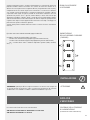
È possibile creare sistemi cardioide utilizzando gruppi di subwoofers.
Un gruppo è costituito di tre moduli disposti come segue:
- 2 moduli rivolti nella direzione di propagazione, pulsante cardioid rilasciato;
- 1 modulo rivolto nella direzione opposta alla propagazione, pulsante cardioid inserito;
- tutti i 3 moduli devono avere le medesime impostazioni generali (ritardo, sensibilità,
xover,…).
IMPOSTAZIONE
DELLA FUNZIONE CARDIOIDE
(CARDIOD)

18
SPECIFICATIONS µ
÷
±
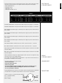
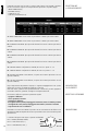
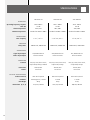
SUB 9007-AS SUB 9006-AS SUB 9004-AS
ACOUSTICAL
Operating frequency response 20 Hz- 400 Hz 30 Hz - 400 Hz 30 Hz - 400 Hz
Max SPL 141 dB 142 dB 136 dB
Hi-Pass Frequencies 25Hz, 35Hz 30Hz, 40Hz 35Hz, 50Hz
Low-Pass Frequencies Variable from 50Hz to 400Hz Variable from 50Hz to 400Hz Variable from 50Hz to 400Hz
TRANSDUCERS
Low frequency 2 x 21”, 4.0” v.c. 2 x 18”neo, 4.0” v.c. 18” neo, 4.0” v.c.
AMPLIFIER
Total power 7200 W Peak, 3600 W RMS 7200 W Peak, 3600 W RMS 2800 W Peak, 1400 W RMS
CONNECTIONS
Signal input/output XLR, RDNet Ethercon XLR, RDNet Ethercon XLR, RDNet Ethercon
Power input/output Powercon IN/OUT Powercon IN/OUT Powercon IN/OUT
PROCESSOR
Controls Gain, EQ, Xover, Phase switch,
Output Delay Settings, Cardioid
Gain, EQ, Preset, Phase switch,
Output Delay Settings
Gain, EQ, Preset, Phase switch,
Output Delay Settings
Protections Thermal, RMS Thermal, RMS Thermal, RMS
Limiter Fast Limiter Fast Limiter Fast Limiter
PHISICAL SPECIFICATIONS
Cabinet material Baltic Birch Plywood Baltic Birch Plywood Baltic Birch Plywood
Hardware Mounting points, 2 x M20 2 x M20 2 x M20
Net Weight 96 Kg 86 Kg 57 Kg
Dimensions (w, h, d) 1135, 825, 760 mm 1188, 785, 558 mm 700, 558, 700 mm

.

10307494 RevB
www.rcf.it
RCF S.p.A.
Via Raffaello Sanzio, 13
42124 Reggio Emilia - Italy
Tel +39 0522 274 411
Fax +39 0522 232 428
e-mail: info@rcf.it
-
 1
1
-
 2
2
-
 3
3
-
 4
4
-
 5
5
-
 6
6
-
 7
7
-
 8
8
-
 9
9
-
 10
10
-
 11
11
-
 12
12
-
 13
13
-
 14
14
-
 15
15
-
 16
16
-
 17
17
-
 18
18
-
 19
19
-
 20
20


RCF SUB 9007-AS Active High Power Subwoofers Manuale del proprietario
- Tipo
- Manuale del proprietario
in altre lingue
Documenti correlati
Altri documenti
-
dBTechnologies DVA S2585N Manuale utente
-
-
-
-
-
 dB VIO S118 Manuale utente
-
-
