RCF EVOX JMIX8 Manuale utente
- Categoria
- Attrezzatura musicale
- Tipo
- Manuale utente

OWNER MANUAL
MANUALE D’USO
EVOX JMIX8
- PROFESSIONAL ACTIVE
TWO-WAY ARRAY
WITH INTERNAL DIGITAL MIXER
- DIFFUSORE ACUSTICO (“ARRAY”)
AMPLIFICATO A DUE VIE
CON MIXER DIGITALE INTEGRATO

TABLE OF CONTENTS
INDICE
ENGLISH
ITALIANO
3
21

3
ENGLISH
IMPORTANT
Before connecting and using this product, please read this instruction manual carefully and
keep it on hand for future reference.
The manual is to be considered an integral part of this product and must accompany it when
it changes ownership as a reference for correct installation and use as well as for the safety
precautions.
RCF S.p.A. will not assume any responsibility for the incorrect installation and / or use of this
product.
WARNING: To prevent the risk of fire or electric shock, never expose this product to rain or
humidity.
SAFETY PRECAUTIONS
1. All the precautions, in particular the safety ones, must be read with special attention, as
they provide important information.
2. POWER SUPPLY FROM MAINS
- Appliance coupler or PowerCon Connector® is used to disconnect device from MAIN
power. This device shall remain readily accessible after the installation
- The mains voltage is sufficiently high to involve a risk of electrocution: never install or
connect this product when its power cord is plugged in.
- Before powering up, make sure that all the connections have been made correctly and the
voltage of your mains corresponds to the voltage shown on the rating plate on the unit, if
not, please contact your RCF dealer.
- The metallic parts of the unit are earthed by means of the power cord.This is a Class I
device and for its use it must be connected to a grounded power source.
- Protect the power cord from damage. Make sure it is positioned in a way that it cannot be
stepped on or crushed by objects.
- To prevent the risk of electric shock, never open this product: there are no parts inside that
the user needs to access.
3. Make sure that no objects or liquids can get into this product, as this may cause a short
circuit. This apparatus shall not be exposed to dripping or splashing. No objects filled with
liquid (such as vases) and no naked sources (such as lit candles) should be placed on this
apparatus.
4. Never attempt to carry out any operations, modifications or repairs that are not expressly
described in this manual.
Contact your authorized service centre or qualified personnel should any of the following
occur:
- The product does not function (or functions in an anomalous way).
- The power cord has been damaged.
- Objects or liquids are inside the product.
- The product has been subject to a heavy impact.
5. If this product is not used for a long period, disconnect its power cord.
6. If this product begins emitting any strange odours or smoke, switch it off immediately and
disconnect its power cord.
7. Do not connect this product to any equipment or accessories not foreseen.
Do not try to hang this product by using elements that are unsuitable or not specific for this
purpose.
To prevent the risk of falling equipment, do not stack multiple units of this product unless this
possibility is specified in the user manual.
IMPORTANT
WARNING
SAFETY PRECAUTIONS

4
ENGLISH
8. RCF S.p.A. strongly recommends this product is only installed by professional qualified
installers (or specialised firms) who can ensure correct installation and certify it according to
the regulations in force.
The entire audio system must comply with the current standards and regulations regarding
electrical systems.
9. Supports and trolleys
The equipment should be only used on trolleys or supports, where necessary, that are
recommended by the manufacturer. The equipment / support / trolley assembly must be
moved with extreme caution.
Sudden stops, excessive pushing force and uneven floors may cause the assembly to overturn.
10. Hearing loss
Exposure to high sound levels can cause permanent hearing loss. The acoustic pressure level
that leads to hearing loss is different from person to person and depends on the duration
of exposure. To prevent potentially dangerous exposure to high levels of acoustic pressure,
anyone who is exposed to these levels should use adequate protection devices.
When a transducer capable of producing high sound levels is being used, it is therefore
necessary to wear ear plugs or protective earphones. See the manual technical specifications
to know the maximum sound pressure level.
11. Situate this product far from any heat sources and always ensure adequate air circulation
around it.
12. Do not overload this product for a long time.
13. Never force the control elements (keys, knobs, etc. ).
14. Do not use solvents, alcohol, benzene or other volatile substances for cleaning the
external parts of this product.
Use a dry cloth.
15. Do not put microphones close and in front of speakers, in order to avoid audio feedback
(‘Larsen effect’).
To prevent the occurrence of noise on microphone / line signal cables, use screened cables
only and avoid putting them close to:
- Equipment that produces high-intensity electromagnetic fields.
- Mains cables.
- Loudspeaker lines.
The equipments considered in this manual can be used in electromagnetic
environment E1 to E3 as specified on EN 55103-1/2: 2009.
Note: This equipment has been tested and found to comply with the limits for a Class A
digital device, pursuant to Part 15 of the FCC Rules. These limits are designed to provide
reasonable protection against harmful interference when the equipment is operated in a
commercial environment. This equipment generates, uses, and can radiate radio frequency
energy, and if it is not installed and used in accordance with the instruction manual, it
may cause harmful interference to radio communications. Operation of this equipment
in a residential area is likely to cause harmful interference, in which case the user will be
required to correct the interference at his own expense.
Modifications: Any modifications made to this device that are not approved by RCF may
void the authority granted to the user by the FCC to operate this equipment.
NOTES ABOUT AUDIO SIGNAL CABLES
FCC RULES

5
ENGLISH
RCF S.P.A. THANKS YOU FOR PURCHASING THIS PRODUCT, WHICH HAS BEEN
MADE TO GUARANTEE RELIABILITY AND HIGH PERFORMANCE.
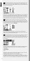
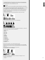
DESCRIPTION
EVOX JMIX8 is a portable active sound system (made of a satellite plus a subwoofer) that
combines quality and reliability of RCF transducers with high amplification power.
It features eight 2.0” full range transducers in the line source satellite and a deep sounding
12” woofer in a bass reflex enclosure.
INTERNAL 8 CHANNEL DIGITAL MIXER
Taking the EVOX J8 one step further, RCF has added an 8-input Digital Mixer to the system.
The onboard processing power of the innovative Z.CORE DSP provides not only full mix
functions it includes high-quality instrument FX and AMP simulations. An EVOX iOS/
Android-compatible app allows to manage the JMIX8. Adding Bluetooth audio and Hi-Z
instrument input, the EVOX JMIX8 combines the quality and reliability of RCF transducers
and amplification with a powerful remote controllable 8-channel digital mixer.
The system is an optimal portable solutions for live music, DJ mix-sets and also presentations,
congresses, other events, etc. .
INNOVATIVE DSP PROCESSING
EVOX DSP processing is the result of many years of experience in line array design
combined with innovative and dedicated algorithms. Thanks to the frequency dependent
drivers excursion and control of distortion, EVOX DSP processing is capable to guarantee
a high output from these small systems. A dedicated vocal processing has been specifically
studied for speech reproduction during presentations or conferences.
RCF TECHNOLOGY
EVOX JMIX8 includes high technology RCF transducers.
The ultra-compact full-range 2” driver can handle extremely high sound pressure levels and
power. The high excursion woofers are able to extend to the lowest frequencies and offer
a quick and precise response up to the crossover point.
Specific attention has been dedicated to mid-low frequencies as well.
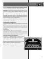
CONTROLLED DIRECTIVITY PATTERN
EVOX array design features a constant horizontal directivity coverage of 120°,
offering a perfect listening experience to the audience.
The vertical array design is progressively shaped to guarantee a correct
listening from the first row.
MULTIFUNCTIONAL TOP HANDLE
The top steel plate joins the handle and the insert for pole mounting.
A rubber hand grip has been added for great portability.
CLASS D AMPLIFICATION
EVOX J8 includes a high power two-way class D amplifier with DSP controlled
crossover.

6
ENGLISH
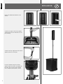
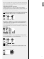
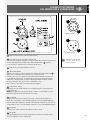
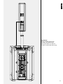
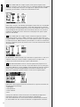
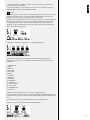
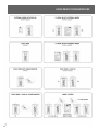
Remove the rubber band and take out the
satellite
Screw the lower part of the satellite speaker
stand (the pole) into the subwoofer insert for
pole mounting.
Screw the telescopic upper part of the satellite
speaker stand into its lower part.
Loose the stand bolt, adjust the satellite
speaker height from the floor and tighten the
bolt again, then insert the satellite speaker
into its complete stand and aim it correctly.
INSTALLATION

7
ENGLISH
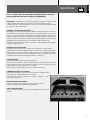
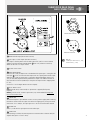
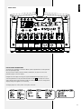
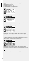
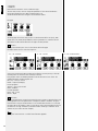
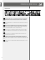
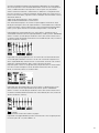
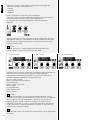
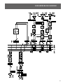
SUBWOOFER REAR PANEL
AND CONNECTIONS
1
Balanced audio input (female XLR connector)
2
Link output - Stereo Output (male XLR connector).
This output is linked in parallel with the audio input and is useful to connect another
speaker (only when the INPUT FROM MIXER
4
LED is off). Otherwise it works by
default as the mixer “R” output channel.
3
System volume control
4
INPUT FROM MIXER
When the LED is OFF, the digital mixer is disabled and the signal input is coming from the
XLR input
1
. In this case the male XLR output works as a regular parallel audio output.
When the LED is ON, the signal input is coming from EVOX JMIX8 digital mixer. In this
case, the male XLR output becomes by default the R output to an addictional EVOX J8.
(The mixer offers a function (SWAP LR) to swap the L-R output channels swapping them
to “R-L”;
See section 11 on the Digital Mixer Instruction Chapter).
5
FLAT / BOOST switch
FLAT (released switch, normal mode): no equalisation is applied (flat frequency
response).
BOOST (pushed switch): ‘loudness’ equalisation, only recommended for background
music at low volume levels.
6
LIMITER LED
The internal amplifier is provided with a limiter circuit to prevent clipping and overdriving
transducers. It blinks when the signal level reaches the clipping point, causing the limiter
intervention. If it is steady lit, the input signal level is excessive and should be reduced.
7
SIGNAL LED
When lit, it indicates the signal presence at the audio input.
8
STATUS LED
When blinking, it indicates the internal protection intervention due to thermal drift (the
amplifier then gets to a “mute” status).
Female XLR connector
PUSH
2 1
3
Male XLR connector
21
3
XLR pins:
1 gRound, 2 audio signaL (+ , hot),
3 audio signaL (–, coLd).
1
2
3
6
7
8
PUSH
2 1
3
21
3
5
4

8
ENGLISH
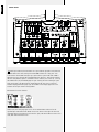
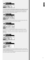
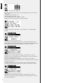
9
Amplifier output to link the satellite speaker.
10
POWER switch
Push it to turn ON / OFF the amplifier.
Before switching the amplifier ON, check all the connections and turn fully
counterclockwise (– ∞) the volume control
3
.
11
VDE Inlet with fuse.
100-120V~ T 6.3 A L 250V
220-240V~ T 3.15 A L 250V
Before connecting the power cord, check if the A/C Power corresponds to the voltage
indicated on the rating plate on the unit. If not, please contact your RCF dealer.
Connect the power cord only to a A/C Power socket outlet with a protective earthing
connection.
When replacing the fuse, refer to the silkscreen indications.
WARNING: the VDE Power Connector is used to disconnect the system from the power
supply network. It must be always easily accessible after the installation and during the
use of the system.
ON
10 11
9

9
ENGLISH
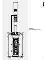
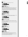
IMPORTANT:
befORe TuRNINg The AMPlIfIeR ON, lINk The
subwOOfeR AMPlIfIeR OuTPuT TO The sATellITe
sPeAkeR INPuT (As shOwN IN The fIguRe)

10
ENGLISH
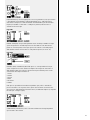
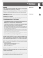
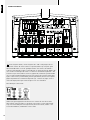
1
MIC/LINE Combo inputs 1 and 2 are provided with switchable 48V Phantom Power;
connect here microphones (XLR) or line sources (TRS jack). It is possible to connect here
Condenser or Electret microphones thanks to the available 48V phantom power.
2
MIC/LINE Combo inputs 3 and 4; connect here dynamic microphones (XLR) or line
sources (TRS jack).
3
HiZ LINE input. LINE input 4 is provided with selectable Hi Impedance input, which
offers optimum reproduction of a guitar or bass guitar even if with passive pick up. The
instrument connected to Line input 4 can take advantage of the MFX section (see section
16 of this manual).
4
Stereo Line input 5 and 6; connect a stereo line source to these TS Jack pair. If
connected alone the input line 5(L) behaves like a mono input.
5
Stereo Line input 7 and 8; connect a low level (-10dBV) stereo line source to these
RCA unbalanced inputs.
6
Footswitch; it allows usage of a dual footswitch, one function can be assigned on the
tip contact and one to the ring contact. Find all the possible assignable function in the
section 16 of the mixer surface description.
7
AUX OUT; this is a balanced output for the auxiliary send available on each input
channel.
ONBOARD DIGITAL MIXER
INSTRUCTIONS
INPUT PANEL

11
ENGLISH
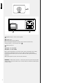
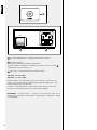
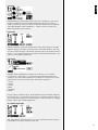
DISPLAY MENU INFORMATION
All the functions available on the EVOX JMIX8 system integrated mixer can be operated
from the operating display.
The select buttons: INPUT, OUTPUT, HOME, SYSTEM, MFX, FX give access to all the
parameter pages on the LCD display.
Navigate into the display menu by pressing the PARAMETER SELECT buttons (12) to
select the parameters to edit, and rotate the EDIT encoder [
13
] to change those values.
Some settings require a push of EDIT encoder to confirm value or function change, and a
display message will appear in this eventuality.
All display pages are usefully shown in the panel silkscreen:
FRONT PANEL

12
ENGLISH
8
MONO input channels; the MIC/LINE 1 to 4 input channels provide a level knob and
an INPUT button. The small yellow point named 0dB indicates the “unity gain” level
of the channel. The SIGNAL LED lights up in green when a signal louder than -40dB is
applied to the input. The red LED located between the channels 1 and 2 knobs indicates
that the +48V phantom power is activated on those channels (see section 16). Pressing
the HOME button (15) the METER page will open showing the level metering of signal
inputs and outputs. The INPUT button, repeatedly pressed, gives access to the four
available display parameters pages (14). The number on the display upper left corner
indicates which input channel is being edited.
INPUT Menus for mono channels:
Page LVL
LEVELS (LVL): this menu page gives access to FX send and AUX send levels for the
specified input. PAN and channel MUTE controls are shown on the right side. The small
rectangular boxes on the bottom line, from left to right, indicate the absolute levels of FX
send, AUX send and Channel Level.
FRONT PANEL

13
ENGLISH
Page EQ
EQUALIZATION (EQ): this menu page gives access to EQ parameters; every input channel
is provided with a three band EQ: LOW and HIGH bands are +/-12dB shelving EQs
with reference frequency at 125Hz and 6.0kHz. The MID BAND EQ provide selectable
frequency from 50Hz to 12kHz and +/-12dB gain. A global EQ ON/OFF control is
available on the lower right.
Page PRE
PREAMP GAIN (PRE): an input GAIN parameter allows to add up to 30dB to the input
signal. HPF performs a selectable High Pass Filter from 20Hz to 1kHz. INV ON/OFF
permits to invert the polarity of the input signal. In the channel 1 and 2 PRE pages a
dedicated box indicates the activation of +48V phantom power (see section 16).
Page DYN
DYNAMIC (DYN): COMPRESSOR; MIC/LINE inputs 1 to 4 are provided with a single
control compressor. The cursor indicates the depth of the compressor intervention. A
dedicated box toggles the compressor ON and OFF. Up to 6 different presets can be
selected from the Compressor Model list:
1. LIGHT
2. HEAVY
3. VOCAL
4. BASS
5. ACOUSTIC
6. DRUM
LINE input 4 is provided with selectable Hi Impedance input, which is available for
passive instruments such as guitars or bass guitars. The instrument connected to Line
input 4 can also take advantage of the MFX section (see dedicated chapter 17). Page PRE
for LINE input 4 changes slightly:
Ch.4 LINE IN Page PRE
A dedicated box, labeled HI-Z, allows to activate and deactivate the High Impedance
input on LINE 4: HI-Z ON/OFF.

14
ENGLISH
9
STEREO LINE input channel 5/6: connect to these TS jacks any analog stereo source.
Control the stereo channel level with the dedicated knob: The SIGNAL LED lights up in
green when a signal louder than -40dB is applied to the input. Pressing the INPUT button
gives the access to display menus:
Page LVL
LEVELS (LVL): as for the MONO channels, this menu page gives access to the channel FX
send, AUX send. BAL (balance) and channel MUTE controls are shown on the right side.
When pressed, the MUTE button also affects FX and AUX sends. The small rectangular
boxes on the bottom line, from left to right, indicate the absolute levels of FX send, AUX
send and Channel Level. All the other pages are same as MONO channels input.
10
STEREO LINE 7/8: connect to these RCA connectors any low level analog stereo
source (-10dBV). Control the stereo channel level with the dedicated knob: the SIGNAL
LED lights up in green when a signal louder than -40dB is applied to the input. Pressing
the INPUT button gives the access to display menus. The control pages of channels 7/8
are same as channel 5/6 except for the PRE page:
From the dedicated box called DUCKER it is possible to activate a ducker gate on
channels 7/8. The control key for the ducker is always the signal present on MIC input 1.
Channel 7/8 is also used for Bluetooth audio input.
11
MAIN LEVEL: MAIN LEVEL controls the master signal level; it provides a control level
knob and an OUTPUT button. The small yellow point named 0dB indicates the “unity
gain” level of the Main Mix. Press the button HOME (15) to show the METER page which
includes level metering of L-R output. Pressing the OUTPUT button gives access to the
following pages:
OUT page: in this page a drop down menu shows one of the four selectable mastering
presets. Rotate and press the EDIT encoder to select a different mastering preset:
1. MASTERING
2. MASTER BOOST
3. LOUD & PROUD
4. HI-FI
These presets combine the action of an Exciter and a Maximizer to apply nice dynamic
and frequency response improvement to the Master signal.
A dedicated box MP ON/OFF permits to turn on and off this feature.
The STEREO box ON/OFF allows to select the chosen system configuration: using the
EVOX JMIX8 as a stand alone speaker, the STEREO box has to be set to OFF. Using EVOX
8 JMIX8 + EVOX J8 as a stereo configuration, the STEREO BOX has to be set to ON. In

15
ENGLISH
this case the EVOX JMIX8 outputs the LEFT channel and the EVOX J8 outputs the RIGHT
channel. If the environment or the setup does not permit the correct positioning of EVOX
JMIX8 as left channel and EVOX J8 as right channel, it is possible to reverse the stereo
image using the box called SWAP LR:
SWAP LR OFF: EVOX JMIX8 LEFT – EVOX J8 RIGHT
SWAP LR ON: EVOX JMIX8 RIGHT – EVOX J8 LEFT
A MUTE box completes the set of controls on this page. Selecting the MUTE box
interrupts the signal flow through the MAIN stereo channel. The numeric window in the
lower right display corner shows the nominal level of the MAIN LEVEL knob. The small
round point on the knob scale indicates the 0.0dB level.
MAIN GEQ page: this page gives access to the 7 band Graphic EQ available on MAIN
channel. Select each single band of the EQ using the “PARAMETER SELECT” buttons
[
12
] and rotate the EDIT encoder to change value. A value box shows the variation in dBs
of the selected band. A dedicated box permits to turn ON and OFF the entire EQ.
AUX OUT page: this page gives access to the master level control of the AUX bus with
a dedicated graphic fader. L+R ON/OFF box permits to assign the MAIN MIX signal,
summed in mono, to the AUX bus. PRE/POST ON/OFF box allows to derive the AUX signal
before or after the channel level control.
Set this control to OFF for AUX PRE and ON for AUX POST. FX RTN ON/OFF box permits
to assign the internal effect return to the AUX bus. The MUTE box, if selected, mutes the
AUX bus output.
AUX GEQ page: this page gives access to the 7 band Graphic EQ available on AUX bus.
Select each single band of the EQ using the “PARAMETER SELECT” button and rotate
the EDIT encoder to change value. A value box shows the variation in dBs of the selected
band. A dedicated box permits to turn ON and OFF the entire EQ.
15
HOME Button:
The HOME button gives access to three pages: MTR Page, INFO Page and “I/0” Page.
MTR page: on the METER page it’s possible to view all the mixer signal levels: Inputs
from 1 to 8, AUX and MAIN L/R.

16
ENGLISH
Pressing the HOME button again gives access to the INFO page where the following is
shown:
FIRMWARE: firmware version - x.xx
BT ID: Bluetooth Identification – 123x
BT STAT: Bluetooth status - (OFF/PAIRING/ONLINE)
USB STAT: USB connection status - (OFFLINE/ONLINE)
Pressing the HOME button again gives access to the “I/0” MIXER ENABLE DISABLE page.
This menu allows to disable the mixer in an EVOX JMIX8 system. Turn the EDIT encoder
counterclockwise to change the menu line from MIXER ENABLE to MIXER DISABLE, press
the EDIT encoder, a display message will appear:
DISABLE MIXER – PRESS ENCODER TO CONFIRM – PRESS ANY KEY TO CANCEL
By pressing the EDIT encoder again, the mixer is disabled and the LCD display backlight
will switch off in 3 seconds.
Now the mixer is disabled, and the EVOX JMIX8 can be used like a conventional active
speaker using the XLR connection located on the subwoofer back panel as mono input.
To enable the mixer again, turn clockwise the EDIT encoder, the display will switch on
again, press the EDIT encoder and a display message will appear:
ENABLE MIXER – PRESS ENCODER TO CONFIRM – PRESS ANY KEY TO CANCEL
Pressing the EDIT encoder the EVOX JMIX8 mixer is enabled again and the system turns
to full operation.
16
SYSTEM button:
Pressing the button once gives access to the LOAD SHOW page;

17
ENGLISH
It is possible to load a pre-saved SHOW from the dedicated menu. A SHOW preset includes
all the mixer parameters except the INPUT and MAIN level. These parameters are absolute
values and can be controlled via pot knobs only. The possible selection is between 10
presets (01 to 10) plus a special preset n°11 called RESET MIXER. Loading the RESET
MIXER preset brings the mixer to a default setting.
To load a preset rotate the EDIT encoder clockwise, select the chosen preset and confirm
the selection pressing the EDIT encoder. A message will appear:
LOAD PRESET “XX” – PRESS ENCODER TO CONFIRM - PRESS ANY KEY TO CANCEL
Press the EDIT encoder again to load the selected preset, or press any key to cancel the
operation.
When a preset is loaded, this information will appear in a dedicated area on the LOAD
SHOW page.
SAVE SHOW page:
The SAVE SHOW page permits to save all the parameters of the mixer in a preset. Again,
the INPUT and MAIN level are excluded from the preset data, they are absolute values and
can be controlled via pot knobs only.
Select a preset location from the dedicated menu rotating the EDIT encoder, then press the
EDIT encoder; a display message will appear:

18
ENGLISH
SAVE PRESET “XX” – PRESS ENCODER TO CONFIRM - PRESS ANY KEY TO CANCEL
By pressing the EDIT encoder, the preset will be stored. If the selected preset is already in
use a message will appear:
OVERWRITE PRESET “XX” – PRESS ENCODER TO CONFIRM - PRESS ANY KEY TO
CANCEL
By pressing the encoder again will store the preset, while pressing any key will cancel the
operation.
By pressing the SYSTEM button once more, the SET page is shown:
The SET page allows to access to some important mixer settings.
The boxes from top left to bottom:
+48V ON/OFF: enables or disables +48 V phantom power on MIC inputs 1 and 2.
BLUETOOTH ON/OFF: enables or disables the Bluetooth connection both for audio
streaming and control.
STARTUP DEFAULT ON/OFF: if this box is set to OFF when the system is switched on, the
mixer keeps its last status when turned off. If the box is set to ON, the mixer is switched
on with a default configuration.
The BACKLIGHT and CONTRAST boxes permit to set brightness and contrast of the LCD
display.
Pressing the SYSTEM button again gives access to the FSW page dedicated to assign
footswitch functions (see section 6 in the input panel description).
FSW page:
The FSW page is composed of three menus: TIP FUN, RING FUN, POLARITY
1. TIP FUN (Tip jack contact function) including:
- MUTE OUTS
- FX ON/OFF
- MFX CHAN A/B
- MFX ON/OFF
- MFX AMP ON/OFF
- MFX MOD ON/OFF
- MFX DLY ON/OFF
- SHOW NEXT
- SHOW PREV
- MASTER PROC ON/OFF

19
ENGLISH
2. The RING FUN (Ring function) provides the same selections as for TIP FUN menu.
3. A POLARITY menu allows to change the initial status of the connected footswitch
between NORMALLY CLOSED and NORMALLY OPEN.
17
MFX button:
The MFX button controls the menu related to the MFX chain present on LINE input 4.
Two local settings of the whole MFX are available, called Channel A and B. It is possible
to switch between A and B using the footswitch (see dedicated function).
The SET page allows to select between FX channel A or B with the dedicated knob icon.
MFX ON/OFF box allows to turn on and off the MFX chain. The AMP, MOD, DLY ON/
OFF boxes located in the bottom line of the display turn on and off individually the
components of the MFX chain:
AMP (Guitar & Bass amp simulator), MOD (modulations effects), DLY (delay).
Pressing the MFX button again gives access to the AMP page:
AMP page: using the AMP MODEL menu on the bottom of the display, it is possible to
select one of the 15 amp simulations by OVERLOUD
TM
:
1. DARKFACE ‘65
2. JAZZ C
3. ROCK’64
4. ROCK 800
5. ROCK 900
6. TOP 30
7. MODERN
8. BASSAMP
9. BASSMATE
10. MARKBASS 1
11. MARKBASS 2
12. SLO 88 CRUNCH
13. SLO 88 LEAD
14. OVERANGE 120
15. HEAVY 51
Rotate the EDIT encoder to select an AMP Simulation model.
The top line of rotary controls allows to change the parameters of the selected AMP
model: DRV (Drive), BASS (Bass frequencies), MID (Mid frequencies), TRB (Treble-High
frequencies).
The AMP ON/OFF box allows to bypass the amp simulator.
Press MFX again to access to MOD page:
MOD page: use the MOD. PRESET menu on the bottom of the page to select a
modulation program between:
1. CHORUS

20
ENGLISH
2. FLANGER
3. TREMOLO
Rotate the EDIT encoder to select a modulation type.
The two rotary controls allow to change the parameters of the selected modulation
preset: DEP (Depht) from 0 to 100%, and RATE (rate) in Hz.
The MOD ON/OFF box allows to bypass the modulation module.
DLY page:
The Delay page shows three rotary controls to edit the DELAY effect: LEV (level), TIME
(Delay time) in ms, FDBK (Delay feedback). Set these parameters to create the favorite
delay effect. The DLY ON/OFF box allows to bypass the delay module.
18
FX button:
Pressing the FX button gives access to the internal effects edit page.
FX PRESET menu allows to select the FX presets:
01 – 40 – REVERBS 41 – 60 – DELAYS
61 – 80 – MODULATIONS
Select a preset rotating the EDIT encoder and confirm the selection pressing it. The ON/
OFF box permits to switch the effect send (FX) on and off.
Each program shows two editable parameters and an effect return level control. The
editable parameters for REV programs are:
DEC (sec) – Decay in seconds
DAMP – Frequency Damping
For DLY programs:
TIM (ms) – time in milliseconds
FDBK – Feedback
For MOD programs:
RATE – rate (in Hz)
DEPTH – depth
19
PAIR button.
Pressing the PAIR button initiates the Bluetooth discovery sequence, required when a new
pairing operation has to be performed on a smartphone, tablet or notebook. The green
LED will blink as long as a Bluetooth device is associated. When the device is connected,
the green LED will be steadily lit. Now it is possible to control the EVOX JMIX8 system via
the Android or iOS app. Furthermore, a Bluetooth audio streaming is enabled to stereo
channel 7/8 (see section 10 of this chapter)
20
USB.
The “type B” USB connector is used for future firmware upgrades.
La pagina si sta caricando...
La pagina si sta caricando...
La pagina si sta caricando...
La pagina si sta caricando...
La pagina si sta caricando...
La pagina si sta caricando...
La pagina si sta caricando...
La pagina si sta caricando...
La pagina si sta caricando...
La pagina si sta caricando...
La pagina si sta caricando...
La pagina si sta caricando...
La pagina si sta caricando...
La pagina si sta caricando...
La pagina si sta caricando...
La pagina si sta caricando...
La pagina si sta caricando...
La pagina si sta caricando...
La pagina si sta caricando...
La pagina si sta caricando...
La pagina si sta caricando...
La pagina si sta caricando...
La pagina si sta caricando...
La pagina si sta caricando...
-
 1
1
-
 2
2
-
 3
3
-
 4
4
-
 5
5
-
 6
6
-
 7
7
-
 8
8
-
 9
9
-
 10
10
-
 11
11
-
 12
12
-
 13
13
-
 14
14
-
 15
15
-
 16
16
-
 17
17
-
 18
18
-
 19
19
-
 20
20
-
 21
21
-
 22
22
-
 23
23
-
 24
24
-
 25
25
-
 26
26
-
 27
27
-
 28
28
-
 29
29
-
 30
30
-
 31
31
-
 32
32
-
 33
33
-
 34
34
-
 35
35
-
 36
36
-
 37
37
-
 38
38
-
 39
39
-
 40
40
-
 41
41
-
 42
42
-
 43
43
-
 44
44


RCF EVOX JMIX8 Manuale utente
- Categoria
- Attrezzatura musicale
- Tipo
- Manuale utente
in altre lingue
- English: RCF EVOX JMIX8 User manual
Documenti correlati
-
RCF EVOX 12 Manuale utente
-
RCF EVOX 5 V2 Manuale del proprietario
-
RCF F 10XR Manuale utente
-
RCF F 6X Manuale utente
-
RCF M 18 Guida Rapida
-
-
-
-
-
RCF NX L-24A Manuale del proprietario
Altri documenti
-
Pioneer XPRS1182S Manuale del proprietario
-
Pioneer XPRS122 Manuale del proprietario
-
HK Audio Polar 12 Manuale utente
-
NGS NETSTEREO Scheda dati
-
LD Systems LDDS21 Manuale utente
-
Eventide Space Guida utente
-
-
-
-
LD Systems ICOA 12 A Manuale del proprietario