
LDP200-120
INPUT:
200 – 500 VAC, 1.4 – 0.5 A (single or two phase) or 250 – 725 VDC
OUTPUT:
24 – 120 VDC, 3 A Max (200 W Max)
MAIN FEATURES
• High efficiency and compact size
• Active PFC
• Digital control
• Wide input voltage range 170 - 550 VAC
• Wide output voltage range 24 - 120 VDC, user
settable
• User settable current limitation threshold
• Remote ON/OFF or other remote-control functions
possible through ENABLE input
• Modbus over RS-485 interface for control and
monitoring
• Multiple protections
• 2 user programmable voltage steps with settable
duration
• Can be used as battery charger (lead acid, nickel,
lithium)
• Can be used for LED lighting
• Can be paralleled for power or redundancy (with
external ORing module)
• Up to 50°C operating temperature with no
derating
• Suitable for POWERMASTER software (available
for Windows and Android)
Use latest device Documentation, Software and Firmware to ensure reliable operation of the system (downloadable from belfuse.com/power-solutions).
READ THIS CAREFULLY BEFORE
INSTALLATION!
VOR DER INSTALLATION BITTE FOLGENDE
SICHERHEITSHINWEISE BEACHTEN!
LEGGERE ATTENTAMENTE PRIMA
DELL’INSTALLAZIONE!
A LIRE ATTENTIVEMENT AVANT
L’INSTALLATION!
Before operating, read this document
thoroughly and retain it for future reference.
Non-respect of these instructions may reduce
performances and safety of the devices and
cause danger for people and property.
The products must be installed, operated,
serviced and maintained by qualified
personnel in compliance with applicable
standards and regulations.
Do not open the device, it does not contain
replaceable components, the tripping of the
internal fuse (if included) is caused by an
internal failure.
Do not repair or modify the device, if
malfunction or failure should occur during
operation, send unit to the factory for
inspection.
No responsibility is assumed by Bel for any
consequences deriving from the use of this
material.
Lesen Sie dieses Dokument vor der
Inbetriebnahme sorgfältig durch und bewahren Sie
es zum späteren Nachschlagen auf.
Die Nichtbeachtung dieser Anweisungen kann die
Funktion und Sicherheit der Geräte beeinträchtigen
und birgt Gefahren für Personen und Eigentum.
Die Geräte müssen von qualifiziertem Personal
unter Einhaltung der geltenden Normen und
Vorschriften installiert, betrieben, gewartet und
instand gehalten werden.
Öffnen Sie das Gerät nicht, es enthält keine
austauschbaren Komponenten, das Auslösen der
internen Sicherung (falls vorhanden) ist stets auf
tiefergehende Fehler im Schaltkreis zurück zu
führen.
Reparieren oder modifizieren Sie das Gerät nicht.
Sollte während des Betriebs eine Fehlfunktion oder
ein Defekt auftreten, schicken Sie das Gerät zur
Überprüfung ins Werk.
Bel übernimmt keine Haftung für die Folgen, die
sich aus dem Einsatz dieses Gerätes ergeben.
Prima dell’installazione, leggere attentamente
questo documento istruzioni e conservarle per
future consultazioni.
L’inosservanza delle presenti istruzioni può
compromettere le caratteristiche e la
sicurezza dell’apparecchio e causare pericolo
per le persone e le cose.
Il prodotto deve essere installato, utilizzato e
riparato da personale qualificato e nel rispetto
delle normative vigenti.
Non aprire il prodotto, esso non contiene
componenti sostituibili, il guasto del fusibile
interno (se previsto) è causato da un guasto
interno.
Non tentare di riparare o modificare il
prodotto, se durante il funzionamento si
verificano guasti o anomalie, inviarlo al
produttore per il controllo.
Bel non si assume nessuna responsabilità per
qualunque conseguenza derivante dall’uso di
questo materiale.
Lire ces instructions avant l'installation,
conserver ce manuel pour référence future.
Défaut de se conformer à ces instructions
peut affecter les caractéristiques et la sécurité
du dispositif, et causer du danger aux
personnes ou aux biens.
Les produits doivent être installés, exploités
et entretenus par du personnel qualifié et en
conformité avec les règlements.
N'ouvrez pas le produit, il ne contient aucune
pièce réparable, le déclenchement du fusible
interne (le cas échéant) est causé par un
défaut interne.
Ne pas essayer de réparer ou modifier le
produit ; si des défaillances se produisent
pendant le fonctionnement, retourner le
produit au fabricant pour inspection.
Bel n'assume aucune responsabilité des
conséquences éventuelles découlant de
l'utilisation des produits.
CAUTION
ACHTUNG
ATTENZIONE
AVVERTISSEMENT
RISK OF BURNS, EXPLOSION, FIRE,
ELECTRICAL SHOCK, PERSONAL INJURY.
Never carry out work on live parts! Danger of
fatal injury!
The product’s enclosure may be hot, allow
time for cooling product before touching it.
Do not allow liquids or foreign objects to enter
into the products.
To avoid sparks, do not connect or
disconnect the device before having
previously turned-off input power and wait for
internal capacitors discharge (minimum 1
minute).
GEFAHR VON VERBRENNUNGEN,
EXPLOSIONEN, FEUER, STROMSCHLAG,
PERSONENSCHÄDEN.
Führen Sie niemals Arbeiten an
spannungsführenden Teilen durch! Gefahr von
tödlichen Verletzungen! Das Gehäuse des Gerätes
kann heiß sein, lassen Sie Zeit zum Abkühlen des
Gerätes, bevor Sie es berühren.
Lassen Sie keine Flüssigkeiten oder Fremdkörper
in die Geräte eindringen.
Um Überschläge zu vermeiden, schließen Sie das
Gerät nicht an oder trennen Sie es nicht ohne
vorher die Eingangsspannung abgeschaltet zu
haben, und warten Sie die Entladung der internen
Kondensatoren ab (mindestens 1 Minute).
RISCHIO USTIONI, ESPLOSIONE,
INCENDIO, SCOSSA, LESIONI GRAVI.
Non effettuare mai operazioni sulle parti sotto
tensione! Pericolo di lesioni letali!
Il contenitore può scottare, lasciar quindi
raffreddare il dispositivo prima di toccarlo.
Non far entrare liquidi o oggetti estranei nel
dispositivo.
Per evitare scintille, non collegare o scollegare
l'apparecchiatura prima di avere tolto tensione
di ingresso e prima che sia avvenuta la
scarica dei condensatori interni (min. 1
minuto).
RISQUE DE BRULURES, EXPLOSION,
INCENDIE, ELECTROCUTION, DOMMAGE
AUX PERSONNES.
Ne jamais effectuer des opérations sur les
parties sous tension! Danger de mort!
Le boîtier peut produire des brûlures, le
laisser refroidir avant de toucher l'appareil. Ne
faire pas pénétrer des liquides ou des corps
étrangers dans l'appareil.
Pour éviter des étincelles, ne pas connecter
ou déconnecter l'équipement jusqu'à ce que
la tension d'entrée a été supprimée et avant
qu'il n'ait eut lieu la décharge des
condensateurs internes (minimum 1 minute).
INTENDED USE
BESTIMMUNGSGEMÄßER BETRIEB
USO PREVISTO
UTILISATION
These are isolated devices suitable for SELV
and PELV circuitry and are designed to be
mounted on DIN rail and installed inside a
protective enclosure. They are intended for
general use such as in industrial control,
communication, and instrumentation
equipment.
Do not use these devices in applications
where malfunction may cause injury or death.
Es handelt sich um galvanisch getrennte Geräte,
die für SELV- und PELV-Anwendungen geeignet
sind und für die Montage auf DIN-Schienen und die
Installation in einem Schutzgehäuse konzipiert
sind. Sie sind für den allgemeinen Gebrauch wie
z.B. in industriellen Steuer-, Kommunikations- und
Automatisierung-Anwendungen vorgesehen.
Verwenden Sie diese Geräte nicht in
Anwendungen, bei denen eine Fehlfunktion zu
Verletzungen oder zum Tod führen kann.
I dispositivi sono isolati, adatti per applicazioni
SELV e PELV, sono dotati di aggancio per il
montaggio su guida DIN all’interno di quadri
elettrici o contenitori di protezione, per
l’utilizzo con controllori industriali, unità di
comunicazione o apparecchi di misura.
Non utilizzare in applicazioni in cui un
eventuale guasto può comportare rischio di
lesioni o di morte.
Les produits sont isolés, appropriés pour les
circuits TBTS et TBTP et sont équipés d'un
crochet pour montage sur rail DIN dans des
armoires ou conteneurs de protection, pour
utilisation avec les contrôleurs industriels, des
modules de communication ou des unités de
mesure.
Ne pas utiliser ces dispositifs dans une
application où un dysfonctionnement pourrait
entraîner le risque des blessures ou de mort.
ENVIRONMENTAL CHARACTERISTICS
UMGEBUNGSBEDINGUNGEN
CARATTERISTICHE AMBIENTALI
CARACTÉRISTIQUES ENVIRONMENTALES
Installation in a Pollution Degree 2
environment.
Do not use in wet area or subject to moisture.
Carefully recycle the product and related
batteries according to local regulations.
Installation in einer Umgebung mit
Verschmutzungsgrad 2.
Nicht in nassen Bereichen oder unter Feuchtigkeit
verwenden.
Das Gerät und die zugehörigen Batterien sind
entsprechend den lokalen Vorschriften zu recyceln
bzw. zu entsorgen.
Usare in ambienti con Grado di Inquinamento
2.
Non far funzionare l'apparecchio in un
ambiente umido o soggetto a formazione di
condensa. Riciclare il prodotto e le batterie
collegate, nel rispetto delle normative locali
vigenti.
Utiliser les produits dans des environnements
avec degré de pollution 2.
Ne pas employer l'appareil dans un
environnement humide ou soumis à la
condensation. Recycler les produits et les
batteries, conformément à la réglementation
locale.

Manufacturer
Bel Fuse Inc.
300 Executive Drive, Suite 300
West Orange, NJ 07052
USA
Asia-Pacific
+86 755 2988 5888
Europe, Middle East
+353 61 49 8941
North America
+1 866 513 2839
belfuse.com/power-solutions
© 2023 Bel Fuse Inc.
BCM.00483_AE
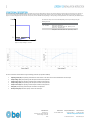
This unit works as a constant voltage source or a constant current source depending on the load. The output voltage is constant until the nominal current is reached. If
more current is needed by the load the device reduces the output voltage to ensure the nominal current is not exceeded. The U/I behavior of the output is shown on
Figure 2, nominal voltage (Unom) and nominal current (Inom) are user settable and, depending on the operating mode (explained be can be altered by the ENABLE input.
Figure 2: Output voltage vs. Current
The maximum output current is limited depending on the output voltage using the
following formula:
RANGE
MAXIMUM OUTPUT CURRENT
24. – 48 VDC
Imax =5 A - (Unom/24)
Example: if Uout=36V, Imax= 5A - (36/24) = 3.5 A
48. – 120 VDC
Imax = 4 A - (3*Unom/144)
Example: if Uout=72V, Imax= 4A - (3*72/144) = 2.5 A
The user can define the device behavior using the following parameters (set by HMI or Modbus):
• Operating mode (OP): The operating mode defines the main behavior of the device. Each mode is described later on this chapter.
• Output voltage 1 (U1): See operating mode description for details of this parameter.
• Output current 1 (I1): See operating mode description for details of this parameter.
• Output voltage 2 (U2): See operating mode description for details of this parameter.
• Output current 2 (I2): See operating mode description for details of this parameter.
• Delay (Del): See operating mode description for details of this parameter.
• Enable polarity (Pol): Defines the polarity used for the enable input.
Uout
Iout
5
V
Unom
Inom

Manufacturer
Bel Fuse Inc.
300 Executive Drive, Suite 300
West Orange, NJ 07052
USA
Asia-Pacific
+86 755 2988 5888
Europe, Middle East
+353 61 49 8941
North America
+1 866 513 2839
belfuse.com/power-solutions
© 2023 Bel Fuse Inc.
BCM.00483_AE
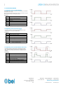
1.1 OPERATING MODES
1.1.1 Operating mode 1 (enable/disable)
In operating mode 1 the device output is turned ON/OFF by the ENABLE
input (default value= LOW).
By setting the appropriate voltage and current this mode allows using the
device as battery charger and LED lighting supply
Parameters:
OP
1
U1
Nominal voltage with output ON
I1
Nominal current with output ON
U2
Not used
I2
Not used
Del
Not used
Pol
Lo or Hi
Figure 3: Operating mode 1
1.1.2 Operating mode 2 (external toggle)
In operating mode 2 the device output toggles between 2 sets of
voltage and current through the ENABLE input.
Parameters:
OP
2
U1
Nominal voltage with enable 1
I1
Nominal current with enable 1
U2
Nominal voltage with enable 0
I2
Nominal voltage with enable 0
Del
Not used
Pol
Lo or Hi
Figure 4: Operating mode 2
1.1.3 Operating mode 3 (enable/disable with timer)
In operating mode 3 the device output is activated by the enable
input. The output toggles to the second set of voltage and current
after a defined time. Output deactivates when the ENABLE input is
disabled.
Parameters:
OP
3
U1
First nominal voltage
I1
First nominal current
U2
Second nominal voltage
I2
Second nominal current
Del
Delay for switching between U1/I1 to U2/I1
Pol
Lo or Hi
Figure 5: Operating mode

Manufacturer
Bel Fuse Inc.
300 Executive Drive, Suite 300
West Orange, NJ 07052
USA
Asia-Pacific
+86 755 2988 5888
Europe, Middle East
+353 61 49 8941
North America
+1 866 513 2839
belfuse.com/power-solutions
© 2023 Bel Fuse Inc.
BCM.00483_AE
1.2 INTERFACES
1.2.1 HMI (Human Machine Interface)
An integrated user interface composed by 3 x 7 segment digits and 3 keys is present on the unit’s front panel. Layout of the menu is shown below:
Figure 6: HMI

Manufacturer
Bel Fuse Inc.
300 Executive Drive, Suite 300
West Orange, NJ 07052
USA
Asia-Pacific
+86 755 2988 5888
Europe, Middle East
+353 61 49 8941
North America
+1 866 513 2839
belfuse.com/power-solutions
© 2023 Bel Fuse Inc.
BCM.00483_AE
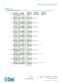
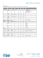
1.2.2 MODBUS
LDP200-120 supports Modbus over RS-485 interface. The following Modbus table is implemented:
Name
Address Hex
(dec)
Modbus
type
Function
code
Res.
Min.
Max.
Comment
Device settings
Operating mode
0x1000
(4096)
Hold register
3,4,6,16
1
1
3
1: enable/disable
2: external toggle
3: enable/disable with timer
See §2.1 for details
Voltage 1
0x1001
(4097)
Hold register
3,4,6,16
0.1V
22V
122V
Current 1
0x1002
(4098)
Hold register
3,4,6,16
0.1A
0A
4.5A
Voltage 2
0x1003
(4099)
Hold register
3,4,6,16
0.1V
22V
122V
Current 2
0x1004
(4100)
Hold register
3,4,6,16
0.1A
0A
4.5A
Delay
0x1005
(4101)
Hold register
3,4,6,16
0.1s
2s
99.9s
Enable
polarity
0x1005
(4102)
Hold register
3,4,6,16
1
1
2
1: active low polarity
2: active high polarity
Modbus settings (loaded on next startup)
Address
0x1100
(4352)
Hold register
3,4,6,16
1
1
247
Baudrate
0x1100
(4353)
Hold register
3,4,6,16
1
1
4
1: 4800
2: 9600
3: 19200
4: 38400
Parity
0x1100
(4354)
Hold register
3,4,6,16
1
1
3
1: None
2: Even
3: Odd
Stop bits
0x1100
(4355)
Hold register
3,4,6,16
1
1
2
1: 1 stop bits
2: 2 stop bits
Metering
Output voltage
0x2000
(8192)
Input
register
3,4
0.1V
0V
148V
Measured output voltage
Input enable
state
0x2000
(8193)
Input
register
3,4
1
0
1
Logical state of the enable input
States
Input under
voltage
0x4000
(16384)
Discrete
input
1,2
1
0
1
1 when the input voltage is too low
Output short
circuit
0x4001
(16385)
Discrete
input
1,2
1
0
1
1 when a short circuit is detected on the output
Over temperature
0x4002
(16386)
Discrete
input
1,2
1
0
1
1 when device is too hot

Manufacturer
Bel Fuse Inc.
300 Executive Drive, Suite 300
West Orange, NJ 07052
USA
Asia-Pacific
+86 755 2988 5888
Europe, Middle East
+353 61 49 8941
North America
+1 866 513 2839
belfuse.com/power-solutions
© 2023 Bel Fuse Inc.
BCM.00483_AE
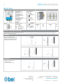
CONNECTIONS
FIG.2 - DIMENSIONS
FIG.3 - DISTANCES
(1) AC input
(2) Enable input
(3) DC output (load)
(4) Display
(5) SET button menu
(6) UP button menu
(7) DOWN button menu
(8) Display
(9) RS-485 Comm. port
Input Connection
Single Phase
▪ L1 = Line
▪ N = Neutral
▪ = earth ground
2 Phases
▪ L1 = Phase 1
▪ L2 = Phase 2
▪ = earth ground
DC:
▪ L1 = + Positive DC
▪ N = - Negative DC
▪ = earth ground
Enable: (5 -30 VDC)
▪ + = Positive DC
▪ - = Negative DC
Output Connection
+ = Positive DC
- = Negative DC
RS-485
Signalling:
DC OK dry contact
24 VDC / 1A
▪ + = NO
▪ - = COM
▪ PIN4 = TX/RX D1
▪ PIN5 = TX/RX D0
▪ PIN8 = GND
Dimension
W
D
H
mm
80
120
112
Distance
A
B
mm
20
50
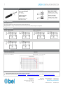
MOUNTING / DISMOUNTING INSTRUCTIONS
For DIN rail fastening according to IEC 60715 TH35-7.5(-15)
Mounting as shown in figure, with input terminals on lower side, with suitable cooling and maintaining a proper distance between adjacent devices as specified in the
Installation Instruction of each family.
MOUNTING:
1. Tilt the unit slightly backwards.
2. Fit the unit over the top edge of the rail.
3. Slide it downward until it hits the stop.
4. Press against the bottom for locking.
1
2
3
4
DISMOUNTING:
1. Pull down the slide clamp lever
2. Tilt the unit upward
3. Unhook the unit from the rail
1 & 2
3

Manufacturer
Bel Fuse Inc.
300 Executive Drive, Suite 300
West Orange, NJ 07052
USA
Asia-Pacific
+86 755 2988 5888
Europe, Middle East
+353 61 49 8941
North America
+1 866 513 2839
belfuse.com/power-solutions
© 2023 Bel Fuse Inc.
BCM.00483_AE
RECOMMENDED CONNECTING CABLE
Recommended Tightening torque
Input / output connections
0.5 - 0.6 Nm
4.42 - 5.30 lbf in
Auxiliary connections
Insertion force per pole
Max 3N or 0.674 lbf
Withdrawal force per pole
Min 1.5N or 0.337 lbf
Input / output connections
Solid: 2.5 mm² / 12 AWG
Stranded:1.5 mm² / 12 AWG
L: 6.0 - 7.5 mm / 0.24 - 0.30 in
Auxiliary connections
Solid: 0.5mm² / 20AWG
Stranded: 0.5mm² / 20AWG
L: 7.0-8.0mm / 0.27-0.315in
INPUT PROTECTION
Fuses MCB 10A C curve
For USA and Canada, use the fuse type closest to the European equivalent type.
Surge protection: it is strongly recommended to provide external surge arresters (SPD) according to local regulations.
INPUT CONNECTIONS
AC LINE – SINGLE PHASE
AC LINE – TWO PHASE
DC LINE
ENVIRONMENT
OPERATING TEMPERATURE
DERATING
- 40°C to + 70°C
5 - 95% r.H. non condensing
Over 60 VDC: - 1.5 W / °C over 50°C
Under 60 VDC: - 3 W / °C over 50°C
NOTES:
▪ Data may change without prior notice in order to improve the product.
▪ Please refer to the latest version of LDP200-120 Datasheet or LDP200-120 Installation Instruction on our wbsite:
belfuse.com/power-solutions
-
 1
1
-
 2
2
-
 3
3
-
 4
4
-
 5
5
-
 6
6
-
 7
7


in altre lingue
- English: BEL LDP200-120 Installation guide
- français: BEL LDP200-120 Guide d'installation
Documenti correlati
-
BEL LDD960-UU Guida d'installazione
-
-
-
-
-
-
-
-
-
Altri documenti
-
Schneider Electric Enerlin’X IFE Ethernet Interface Guida utente
-
WAGO ETHERNET Controller /XTR Manuale utente
-
Rosemount X-STREAM Enhanced XECLD Continuous Gas Analyzer Manuale del proprietario
-
CARLO GAVAZZI WM50AV53HBC Manuale del proprietario
-
Unical ALKON 140 EXT Guida d'installazione
-
gefran 600 Manuale utente