
Kurz−
beschreibung
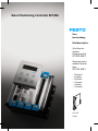
Brief description
Schrittmotor−
Indexer−
Baugruppe Typ
SPC200−SMX−1
Stepping motor
indexer module
type
SPC200−SMX−1
Deutsch
English
Español
Français
Italiano
Svenska
671 596
0309a
Smart Positioning Controller SPC200

Festo SPC200−SMX−1 0309a 2
Deutsch 3 . . . . . . . . . . . . . . . . . . . . . . . . . . . . . . . . . . . . . . . . . . .
English 13 . . . . . . . . . . . . . . . . . . . . . . . . . . . . . . . . . . . . . . . . . . . .
Español 23 . . . . . . . . . . . . . . . . . . . . . . . . . . . . . . . . . . . . . . . . . . .
Français 33 . . . . . . . . . . . . . . . . . . . . . . . . . . . . . . . . . . . . . . . . . . .
Italiano 43 . . . . . . . . . . . . . . . . . . . . . . . . . . . . . . . . . . . . . . . . . . . .
Svenska 53 . . . . . . . . . . . . . . . . . . . . . . . . . . . . . . . . . . . . . . . . . . .
Edition:
0309a
Original: de
© (Festo AG&Co. KG, D73726 Esslingen, Germany, 2003)
Internet: http://www.festo.com
E−Mail: service_international@festo.com

Festo SPC200−SMX−1 0309a Deutsch 3
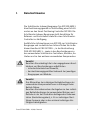
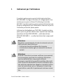
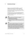
1 BenutzerhinweiseDeutsch
Die Schrittmotor−Indexer−Baugruppe Typ SPC200−SMX−1
dient bestimmungsgemäß zur Anschaltung eines S chritt
motors an den Smart Positioning Controller SPC200. Die
Schrittmotor−Indexer−Baugruppe stellt Anschlüsse für
Referenz− und Endschalter sowie für einen Schrittmotor−
Controller zur Verfügung.
Ausführliche Informationen zum SPC200, zur Schrittmotor−
Baugruppe und zu elektrischen Achsen finden Sie im Be
diener−Handbuch P.BE−SPC200−.., in der Beschreibung
P.BE−SPC200−SMX−1−.. sowie in den Beschreibungen zu
den verwendeten Schrittmotor−Controllern, Motoren, An
trieben un d zu den weiteren verwendeten Komponenten.
Vorsicht
Beachten Sie unbedingt die in den angegebenen Hand
büchern und Beschreibungen aufgeführten
sicherheitstechnischen Hinweise,
den bestimmungsgemäßen Gebrauch der jeweiligen
Baugruppen und Module.
Vorsicht
Das Missachten der zulässigen Betriebsbedingen der
verwendeten Komponenten kann zu Störungen beim
Betrieb führen.
Beachten Sie insbesondere die Angaben zu den zulässi
gen Betriebsbedingen der verwendeten Motoren und
Antriebe in der den Produkten beiliegenden Dokumen
tation (Herstellerangaben), z. B. zur zulässigen Start−
Stopp−Frequenz oder zu den minimal zulässigen Ver
fahrgeschwindigkeiten.

Festo SPC200−SMX−1 0309a Deutsch4
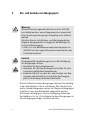
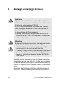
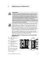
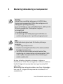
2 Ein− und Ausbau von Baugruppen
Warnung
Aktoren können ungewollt aktiviert und der SPC200
beschädigt werden, wenn Baugruppen bei eingeschal
teter Spannungsversorgung hinzugefügt oder entfernt
werden.
Schalten Sie vor In stallations− und Wartungsarbeiten
folgende Energiequellen in folgender Reihenfolge ab:
4. Druckluftversorgung
5. Alle Last− und Betriebsspannungsversorgungen am
SPC200 und den angeschlossenen Komponenten des
Positioniersystems.
Vorsicht
Unsachgemäße Handhabung kann zur Beschädigung
der Baugruppen führen.
S Berühren Sie keine Bauelemente.
S Beachten Sie die Handhabungsvorschriften für elek
trostatisch ge fährdete Bauelemente.
S Entladen Sie sich vor dem Ein− oder Ausbau von Bau
gruppen elektrostatisch, zum Schutz der Baugrup
pen vor Entladung statischer Elektrizität.
Die Schrittmotor−Indexer−Baugruppen können Sie beliebig
in den Steckplätzen 2 bis 6 installieren. Wird eine Schritt
motor−Indexer−Baugruppe neben der Diagnose−Baugruppe
installiert, kann kein Bedienfeld aufgesteckt werden.
Es können, abhängig von den zur Verfügung stehenden
Steckplätzen, bis zu 3 Schrittmotor−Indexer−Baugruppen in
einen Baugruppenträger installiert werden.

Festo SPC200−SMX−1 0309a Deutsch 5
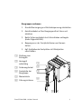
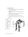
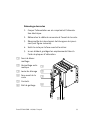
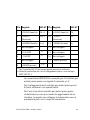
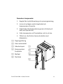
Baugruppen ausbauen
1. Druckluftversorgung und Betriebsspannung abschalten.
2. Anschlusskabel auf der Baugruppenfront lösen und
abziehen.
3. Beide Sicherungshebel durch Versc hieben entriegeln
(siehe folgendes Bild).
4. Baugruppe an der Frontplatte fassen und heraus
ziehen.
5. Ggf. freibleibende Steckplätze mit Blindplatten
verschließen.
1 Richtung zum
Entriegeln
2 Verriegelt
selbsttätig
3 Sicherungshebel
4 Frontplatte der
Baugruppe
5 Messerleiste
6 Führungsschiene
56
1
2
3
4

Festo SPC200−SMX−1 0309a Deutsch6
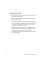
Baugruppen einbauen
1. Druckluftversorgung und Betriebsspannungsversor
gung abschalten.
2. Ggf. Sicherungshebel entriegeln und Blindplatte
entfernen.
3. Baugruppe an der Frontplatte fassen und in die Füh
rungsschiene einschieben. Achten Sie darauf, dass Sie
die Baugruppe beim Einschieben nicht verkantet und
keine Bauteile auf der Leiterplatte beschädigt werden.
4. Achten Sie darauf, dass die Stecker der Messerleisten
richtig aufeinander liegen. Schieben Sie die Bau
gruppe dann mit leichtem Druc k vollständig ein.
Daraufhin verriegeln die Sicherungshebel selbsttätig
(siehe Bild).

Festo SPC200−SMX−1 0309a Deutsch 7
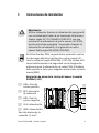
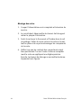
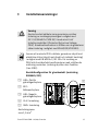
3 Installationshinweise
Warnung
Verwenden Sie nur Netzteile, die eine sichere elektri
sche Trennung der Betriebsspannung nach IEC 742/
EN60742/VDE 0551 mit mindestens 4 kV Isolations−
festigkeit gewährleisten (Protected Extra−Low Voltage,
PELV). Schaltnetzteile sind zulässig, wenn sie die
sichere Trennung im Sinne der EN 60950/VDE 0805
gewährleisten.
Durch die Verwendung von PELV−Netzteilen wird der
Schutz gegen elektrischen Schlag (Schutz gegen direktes
und indirektes Berühren) nach Maßgabe der EN 60204−1/
IEC 204 sichergestellt. Für die Versorgung von PELV−Netzen
sind Sicherheitstransformatoren mit der nebenstehenden
Kennzeichnung zu verwenden. Die Erdung erfolgt zur
Sicherstellung der Fun ktion (z.B. EMV).
Pin−Belegung Sensorstecker (Anschluss SIGNALS, X31)
1 LIM+: Positiver
Endschalter
2 REF: Refe renz
schalter
3 LIM−: Negativer
Endschalter
4 24 V: Einspeisung
5 GND: Einspeisung
Anschlussquerschnitt
max. 1,5 mm
2
1
2
3
4
5

Festo SPC200−SMX−1 0309a Deutsch8
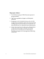
Beschaltung Sensorstecker (Anschluss SIGNALS, X31)
Hinweis
Beachten Sie die verschiedenen Aus führu ngen der Kon
takte für die Endschalter (Öffner N.C., normal closed)
und den Referenzschalter (Schließer N.O., normal
open).
LIM+
REF
LIM−
24V
0V
24V
0V
AC
DC
Die Genauigkeit des Referenzpunkts hängt vom verwende
ten Re ferenzschalter ab. Verwenden Sie einen Referenz
schalter, dessen Umschaltpunkt innerhalb einer Schrittauf
lösung liegt.
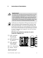
Pin−Belegung Steuerstecker (Anschluss AMPLIFIER, X30)
1
2
8
.
.
.
9
15
.
.
.

Festo SPC200−SMX−1 0309a Deutsch 9
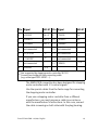
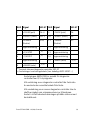
Pin Signal SEC−ST Pin Signal SEC−ST
1 + PULSE (Puls) Clk + 5 9 − PULSE (P uls) Clk −
2 + DIRECT. (Richtg.) Dir + 5 10 − DIRECT. (Richtg.) Dir −
3 + ENABLE (Enable) En + 5 11 − ENABLE (Enable) En −
4 nicht verbunden 12 nicht verbunden
5 + F/H STEP
1)
13 nicht verbunden
6 − F/H STEP
1)
14 nicht verbunden
7 nicht verbunden 15 − READY (Bereit.)
1)
2)
8 + READY (Bereit.)
1)
2)
1)
Beim Schrittmotor−Controller S EC−ST nicht genutzt
2)
Anschlüsse im Anschlusskabel gebrückt (z. B. Kabel Typ
KSPC−SECST−...)
Der Anschluss AM PLIFIER ist ausgelegt für Schrittmotor−
Controller mit 5 V−Steuersignalen.
Verwenden Sie zum Anschluss der Schrittmotor−Controller
von Festo die speziellen Kabel aus dem Zubehör von Festo.
Bei Verwendung eines anderen Schrittmotor−Controllers
konfektionieren Sie ein Kabel entsprechend der Empfeh
lung des Herstellers. Verbinden Sie in diesem Fall den
Kabelschirm auf beiden Seiten mit dem Steckergehäuse.

Festo SPC200−SMX−1 0309a Deutsch10
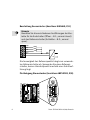
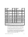
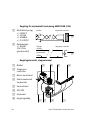
Beschaltung Steuerstecker (Anschluss AMPLIFIER, X30)
1 Gegentakt−
steuerung:
+/− DIRECT.,
+/− PULSE,
+/− ENABLE,
+/− F/H STEP
2 Relaiskontakt:
+/− READY
(24 V von Sensor
stecker)
+...
−...
SPC200 Schri t t m otor−Contr ol l er
+REA DY
−READY
SPC200 Schri t t m otor−Contr ol l er
(+24Vvon
Sensorstecker)
1
2
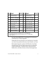
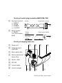
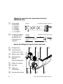
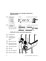
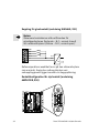
Beschaltungsübersicht Schrittmotorachse
1 Netzteil
2 Schrittmotor−
Controller
3 Motor mit Kabel
4 Elektromecha−
nischer Linear−
antrieb
5 Sensorkabel
6 SPC200
7 Steuerkabel
8 Schaltschrank
87 6 5
4321

Festo SPC200−SMX−1 0309a Deutsch 11
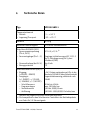
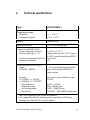
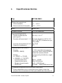
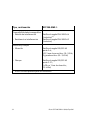
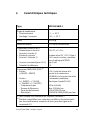
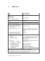
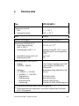
4 Technische Daten
Typ SPC200−SMX−1
Tem peraturbereich
Betrieb
Lagerung/Transport
− 5 ... + 50 °C
− 20 ... +70 °C
Gewicht ca. 69 g
Relative Luftfeuchtigkeit 95 % nicht kondensierend
Anschluss SIGNALS (X31)
Spannungseinspeisung
(Pin 4, Pin 5)
Sensoreingänge (Pin 1...3)
Stromaufnahme (bei 24 V)
Bezugspotential
DC 24 V, ± 15 %
1)
Eingänge in Anlehnung an IEC1131−2
Typ 2, Gleichspannung 24 V, plus
schaltend (PNP)
Typ. 8 mA
0 V
Anschluss AMPLIFIER (X30)
2)
Eingang:
(+ READY, − READY)
Ausgänge:
(+/− DI RECT., +/− PULSE,
+/− ENABLE, +/− F/H STEP)
Schrittfrequenz
Frequenzrampe
Verfahrbereich
Auflösung
+ 24 V (intern verbunden mit Pin4 des
Steckers SIGNALS) über Relaiskontakt
Gegentaktsteuerung, elektrisch nach
RS485
80 Hz bis 40 kHz
max. 500 kHz/sec
0,00 bis 9999,99 mm
0,01000...9999,99999 Schritte/mm
1)
Tolera nz der angeschlossenen Sensoren beachten!
2)
Pin−kompatibel zu den Schrittmotor−Controllern der Antriebspakete
von Festo für 5 V−Steuersignale

Festo SPC200−SMX−1 0309a Deutsch12
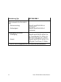
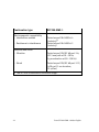
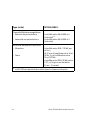
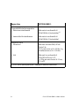
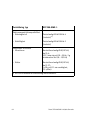
Fortsetzung Typ SPC200−SMX−1
Elektromagnetische Verträglich
keit
Störaussendung
Störfestigkeit
Geprüft nach EN 61000−6−4
(Industrie)
1)
Geprüft nach EN 61000−6− 2
(Industrie)
Schwingung und Schock
Schwingung
Schock
Geprüft nach DIN/IEC 68 Teil 2−6;
0,15 mm Weg bei 10...58 Hz, 2g
Beschleunigung bei 58...150 Hz
Geprüft nach DIN/IEC 68 Teil 2−27;
±30 g bei 11ms Dauer; 15 Zyk len
1)
Der SP C200 ist vorgesehen für den Einsatz im Industriebereich

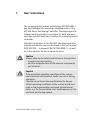
Festo SPC200−SMX−1 0309a English 13
1 User instructionsEnglish
The stepping motor indexer module type SPC200−SMX− 1
has been designed for coupling a stepping motor to the
SPC200 Smart Positioning Controller. The ste pping motor
indexer module provides connections for both reference
switches and limit switches as we ll as for a stepping motor
controller.
Detailed information on the SPC200, the steppin g motor
module and electric axes can be found in the user manual
P.BE−SPC200−.., in manual P.BE−SPC200−SMX−1−.. as well
as in the manuals for the components used.
Caution
Always obs erve the safety instructions in the specified
manuals and descriptions,
and the designated use of the relevant components
and modules.
Caution
If the permitted operating conditions of the compo
nents used are not observed, faults may occur during
operation.
Consider in particular the specifications for the per
mitted operating conditions of the motors and drives
used in the documentation enclosed (manufacturer
data), e.g. for the permitted start−stop frequency or the
minimum positioning speeds.

Festo SPC200−SMX−1 0309a English14
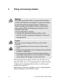
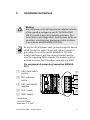
2 Fitting and removing modules
Warning
Actuators may make sudden unexpected movements
and the SPC200 will be damaged if modules are added
or removed whils t the power supply is switched on.
Before carrying out installation and/or maintenance
work, switc h off the following power supplies in the
sequence specified:
1. the compressed air supply
2. all load and operating voltage supplies on the
SPC200 and the connected components of the posi
tioning system.
Caution
Modules may be damaged if they are not handled
correctly.
S Do not therefore touch the contacts of the compo
nents.
S Observe the regulations for handling electrostatically
sensitive components.
S Discharge yourself electrostatically before fitting or
removing components in order to protect the compo
nents against discharges of static electricity.
The stepping motor indexer module can be fitted as de
sired into slots 2 to 6. If a ste pping motor indexer module
is fitted next to the diagnostic module, a control panel
cannot be connected.
Depending on the slots available, up to 3 stepping motor
indexer modules can be fitted in a rack.

Festo SPC200−SMX−1 0309a English 15
Removing modules
1. Switch off the compressed air supply and the operat
ing voltage supply.
2. Loosen and pull off the connecting cable on the front
of the module.
3. Unlock both retaining levers by pushing them back
(see following diagram).
4. Grip the module by the front plate and pull it out.
5. If necessary, seal the unused slots with blanking
plates.
1 Direction for un
locking
2 Locks automati
cally
3 Retaining lever
4 Front plate of the
module
5 Terminal strip
6 Guide rail
56
1
2
3
4

Festo SPC200−SMX−1 0309a English16
Fitting modules
1. Switch off the compressed air supply and the operat
ing voltage supply.
2. If necessary, unlock the retaining lever and remove the
blanking plate.
3. Hold the module by the front plate and push it in to the
guide rail. Make sure that the modules are not tilted
when they are pushed in and that no components on
the printed circuit board are damaged.
4. Make sure that the plugs of the terminal strips are cor
rectly aligned. Then gently push the module in as far
as possible. The retaining levers will then lock auto
matically (see diagram).

Festo SPC200−SMX−1 0309a English 17
3 Installation instructions
Warning
Use only power un its which guarantee re liable isolation
of the operating voltages as per IEC 742/EN 60742/
VDE0551 with at least 4 kV isolation resistance (Pro
tected Extra Low Voltage PELV). Switch power packs are
permitted, providing they guarantee re liable isolation
in accordance with EN 60950/VDE 0805.
By the use of PE LV power units, protection against electric
shock (protection against direct and indirect contact) is
guaranteed in accordance with EN 60204−1/IEC 204.
Safety transformers with the adjacent symbol must be
used for supplying PELV networks. The module must be
earthed to ensure that it functions correctly (e.g. EMC).
Pin assignment of sensor plug (connection SIGNALS,
X31)
1 LIM+: limit switch
positive
2 REF: reference
switch
3 LIM−: limit switch
negative
4 24 V: supply
5 GND: supply
Connection
cross−sectional
area max. 1.5 mm
2
1
2
3
4
5

Festo SPC200−SMX−1 0309a English18
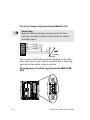
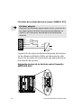
Circuitry of sensor plug (connection SIGNALS, X31)
Please note
Note the different designs of contacts for the limit
switches (normally closed) and the reference switch
(normally open).
LIM+
REF
LIM−
24V
0V
24V
0V
AC
DC
The accuracy of the reference point depends on the refer
ence switch used. Use a reference switch with a switching
point which lies within a step resolution.
Pin assignment of control plug (connection AMPLIFIER,
X30)
1
2
8
.
.
.
9
15
.
.
.

Festo SPC200−SMX−1 0309a English 19
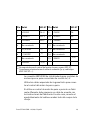
Pin Signal SEC−ST Pin Signal SEC−ST
1 + PULSE Clk + 5 9 − PULSE Clk −
2 + DIRECT. Dir + 5 10 − DIRECT. Dir −
3 + ENABLE EN + 5 11 − ENABLE En −
4 not connected 12 not connected
5 + F/H STEP
1)
13 not connected
6 − F/H STEP
1)
14 not connected
7 not connected 15 − READY
1)
2)
8 + READY
1)
2)
1)
Not supported by stepping motor controller SEC−ST.
2)
Connections bridged in the connecting cable
(e.g. cable type KSPC−SECST−...).
The AMPLIFIER connection has been designed for stepping
motor controllers with 5 V c ontrol signals.
Use the special ca bles from the Festo range for connecting
the stepping motor controller.
If you use a stepping motor controller from a different
manufacturer, you must prepare a c able in accordance
with the manufacturer’s instructions. In this case, connect
the cable screening on both sides with the plug housing.

Festo SPC200−SMX−1 0309a English20
Circuitry of control plug (connection AMPLIFIER, X30)
1 Push−pull control:
+/− DIRECT.
+/− PULSE
+/− ENABLE
+/− F/H STEP
2 Relay contact:
+/− READY
(24 V from sensor
plug)
+...
−...
SPC2 00 Steppermotorcontroller
+REA DY
−READY
SPC2 00 Steppermotorcontroller
(+24Vfrom
sensorplug)
1
2
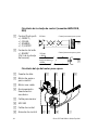
Circuitry of stepping motor axis
1 Power unit
2 Stepping motor
controller
3 Motor with cable
4 Electromechanical
linear drive
5 Sensor cable
6 SPC200
7 Control cable
8 Control cabinet
87 6 5
4321
La pagina sta caricando ...
La pagina sta caricando ...
La pagina sta caricando ...
La pagina sta caricando ...
La pagina sta caricando ...
La pagina sta caricando ...
La pagina sta caricando ...
La pagina sta caricando ...
La pagina sta caricando ...
La pagina sta caricando ...
La pagina sta caricando ...
La pagina sta caricando ...
La pagina sta caricando ...
La pagina sta caricando ...
La pagina sta caricando ...
La pagina sta caricando ...
La pagina sta caricando ...
La pagina sta caricando ...
La pagina sta caricando ...
La pagina sta caricando ...
La pagina sta caricando ...
La pagina sta caricando ...
La pagina sta caricando ...
La pagina sta caricando ...
La pagina sta caricando ...
La pagina sta caricando ...
La pagina sta caricando ...
La pagina sta caricando ...
La pagina sta caricando ...
La pagina sta caricando ...
La pagina sta caricando ...
La pagina sta caricando ...
La pagina sta caricando ...
La pagina sta caricando ...
La pagina sta caricando ...
La pagina sta caricando ...
La pagina sta caricando ...
La pagina sta caricando ...
La pagina sta caricando ...
La pagina sta caricando ...
La pagina sta caricando ...
La pagina sta caricando ...
-
 1
1
-
 2
2
-
 3
3
-
 4
4
-
 5
5
-
 6
6
-
 7
7
-
 8
8
-
 9
9
-
 10
10
-
 11
11
-
 12
12
-
 13
13
-
 14
14
-
 15
15
-
 16
16
-
 17
17
-
 18
18
-
 19
19
-
 20
20
-
 21
21
-
 22
22
-
 23
23
-
 24
24
-
 25
25
-
 26
26
-
 27
27
-
 28
28
-
 29
29
-
 30
30
-
 31
31
-
 32
32
-
 33
33
-
 34
34
-
 35
35
-
 36
36
-
 37
37
-
 38
38
-
 39
39
-
 40
40
-
 41
41
-
 42
42
-
 43
43
-
 44
44
-
 45
45
-
 46
46
-
 47
47
-
 48
48
-
 49
49
-
 50
50
-
 51
51
-
 52
52
-
 53
53
-
 54
54
-
 55
55
-
 56
56
-
 57
57
-
 58
58
-
 59
59
-
 60
60
-
 61
61
-
 62
62


in altre lingue
- français: Festo SPC200 Series
- español: Festo SPC200 Series
- Deutsch: Festo SPC200 Series
Documenti correlati
-
Festo 1451384 Operating Instructions Manual
-
Festo CMMO-ST-xxx-DIOP series Original Instructions Manual
-
-
-
Festo 18225 Manuale utente
-
-
-