Festo 8061196 Operating Instructions Manual
- Tipo
- Operating Instructions Manual

8127157
EMCA-EC-67-...-DIO
Integrated drive
8127157
2020-03d
[8127159]
Operating instructions

Translation of the original instructions
2 Festo — EMCA-EC-67-...-DIO — 2020-03d

3Festo — EMCA-EC-67-...-DIO — 2020-03d
1 Introduction................................................................................................................. 7
2 Safety and requirements for product use.................................................................... 10
2.1 Safety............................................................................................................................ 10
2.1.1 General safety instructions..................................................................................... 10
2.1.2 Intended use...........................................................................................................11
2.2 Requirements for product use...................................................................................... 11
2.2.1 Transport and storage conditions........................................................................... 11
2.2.2 Technical prerequisites...........................................................................................12
2.2.3 Training of qualified personnel............................................................................... 12
2.2.4 Product conformity and approvals.......................................................................... 12
3 Product description..................................................................................................... 13
3.1 Product overview.......................................................................................................... 13
3.1.1 General features of the product.............................................................................. 14
3.1.2 Scope of delivery.................................................................................................... 15
3.1.3 System structure.....................................................................................................16
3.2 Software for configuration and commissioning............................................................ 17
3.2.1 FCT (Festo Configuration Tool)................................................................................ 17
3.2.2 Web server..............................................................................................................17
3.3 Connections and display components.......................................................................... 18
3.4 Drive functions............................................................................................................. 19
3.4.1 Dimension reference system...................................................................................20
3.4.2 Homing................................................................................................................... 23
3.4.3 Jog Mode.................................................................................................................31
3.4.4 Teach-in mode........................................................................................................ 33
3.4.5 Positioning mode....................................................................................................33
3.4.6 Velocity mode......................................................................................................... 36
3.4.7 Force/torque mode.................................................................................................40
3.4.8 Stop (halt), Quick-Stop........................................................................................... 42
3.4.9 Holding brake (only EMCA-EC-...-...-B).....................................................................43
3.5 Operational principle for record selection..................................................................... 44
3.5.1 Record switching.................................................................................................... 45
3.5.2 Record sequencing................................................................................................. 47
3.6 Monitoring of the drive behaviour................................................................................ 48
3.6.1 Messages................................................................................................................48
3.6.2 Comparators........................................................................................................... 51
3.6.3 Protective functions................................................................................................54
3.6.4 Error management.................................................................................................. 54
3.6.5 Diagnostic memory................................................................................................. 56
3.7 Interfaces..................................................................................................................... 56
3.7.1 Ethernet interface [X1]............................................................................................ 56
Table of contents

3.7.2 STO interface [X6].................................................................................................. 58
3.7.3 Functions of the base inputs/outputs.................................................................... 58
3.7.4 Functions of the additional inputs/outputs............................................................ 64
3.8 Control via the I/O interface.......................................................................................... 68
3.8.1 Establishing the ready status................................................................................. 68
3.8.2 Set mode for the I/O interface............................................................................... 68
3.8.3 Enabling and disabling the closed-loop controller................................................. 69
3.8.4 Acknowledge errors............................................................................................... 70
3.8.5 Execute homing..................................................................................................... 71
3.8.6 Jog, teach (mode 1)................................................................................................ 72
3.8.7 Start record (mode 0)............................................................................................. 73
3.8.8 Start, stop and continue record (mode 0).............................................................. 75
3.8.9 Start and stop record, delete remaining path (mode 0)...........................................76
3.8.10 Record switching................................................................................................... 77
3.8.11 Release holding brake (only EMCA-EC-...-...-B)....................................................... 77
4 Assembly......................................................................................................................78
4.1 Dimensions....................................................................................................................78
4.2 Performing mounting.....................................................................................................79
5 Installation...................................................................................................................81
5.1 Safety instructions.........................................................................................................81
5.2 EMC-compliant wiring....................................................................................................82
5.3 Ethernet interface [X1]................................................................................................... 82
5.4 Connection of plugs [X4] ... [X10]................................................................................... 84
5.4.1 Power supply [X4].................................................................................................. 87
5.4.2 Braking resistor [X5]............................................................................................... 89
5.4.3 STO interface [X6].................................................................................................. 90
5.4.4 Limit or reference switch [X7], [X8]......................................................................... 91
5.4.5 I/O interface [X9].................................................................................................... 92
5.4.6 External battery [X10]............................................................................................. 94
5.5 Requirements for ensuring IP degree of protection....................................................... 94
6 Commissioning.............................................................................................................95
6.1 Notes on commissioning............................................................................................... 95
6.2 FCT (Festo Configuration Tool).......................................................................................95
6.2.1 Installing FCT......................................................................................................... 95
6.2.2 Starting FCT........................................................................................................... 96
6.2.3 Notes on commissioning with FCT.......................................................................... 96
6.3 Network connection via Ethernet...................................................................................97
6.3.1 Displaying or changing network configuration....................................................... 99
6.3.2 Security in the network.......................................................................................... 99
6.4 Master control............................................................................................................... 100
4 Festo — EMCA-EC-67-...-DIO — 2020-03d

6.5 Online connection with the web server......................................................................... 102
6.6 Commissioning steps................................................................................................... 103
6.6.1 Configuration and parameterisation....................................................................... 103
6.6.2 Checking STO function............................................................................................104
6.6.3 Checking signal characteristics of the limit and reference switches........................ 104
6.6.4 Providing required signals (digital I/Os)................................................................. 104
6.6.5 Checking direction of rotation/travel direction....................................................... 106
6.6.6 Execute homing...................................................................................................... 107
6.6.7 Testing positioning behaviour (test mode)............................................................. 107
6.6.8 Optimising controller setting (optional).................................................................. 107
6.6.9 Completing commissioning.....................................................................................107
6.7 Saving or loading parameter file................................................................................... 108
6.8 Instructions for operation............................................................................................. 108
6.8.1 Maximum write cycles of the flash memory............................................................ 109
7 Diagnostics and fault clearance.................................................................................. 109
7.1 Access to the diagnostic memory................................................................................. 110
7.2 Diagnostics via LEDs..................................................................................................... 111
7.2.1 Behaviour during the switch-on phase....................................................................111
7.2.2 Behaviour in the operating phase........................................................................... 112
7.2.3 Identification sequence active................................................................................ 112
7.2.4 Behaviour with errors in the firmware update phase.............................................. 112
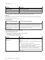
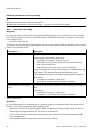
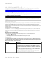
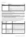
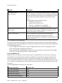
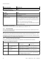
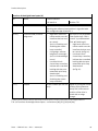
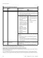
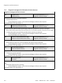
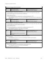
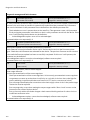
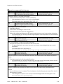
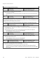
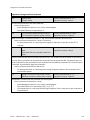
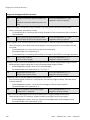
7.3 Diagnostic messages, causes and remedies................................................................. 112
7.3.1 Explanations for the diagnostic messages.............................................................. 112
7.3.2 Diagnostic messages with information for fault clearance...................................... 114
7.4 Problems with the Ethernet connection........................................................................ 129
7.5 Other problems and remedies...................................................................................... 130
8 Maintenance, care, repair and replacement................................................................ 130
8.1 Maintenance and care.................................................................................................. 130
8.2 Disassembly................................................................................................................. 131
8.3 Repair............................................................................................................................132
8.4 Replacement and disposal............................................................................................ 132
8.4.1 Disposal..................................................................................................................132
9 Technical appendix..................................................................................................... 132
9.1 Technical data.............................................................................................................. 132
9.1.1 General technical data............................................................................................ 132
9.1.2 Product conformity and approvals.......................................................................... 133
9.1.3 Mechanical data......................................................................................................133
9.1.4 Operating and ambient conditions..........................................................................133
9.1.5 Data for the integrated motor................................................................................. 135
9.1.6 Data for the integrated rotor position encoder........................................................135
5Festo — EMCA-EC-67-...-DIO — 2020-03d

9.1.7 Holding brake (only EMCA-EC-...-...-B).................................................................... 136
9.1.8 Ethernet interface [X1]........................................................................................... 136
9.1.9 Power supply [X4].................................................................................................. 136
9.1.10 Braking resistor [X5]............................................................................................... 137
9.1.11 STO interface [X6].................................................................................................. 137
9.1.12 Reference or limit switch [X7], [X8]......................................................................... 137
9.1.13 I/O interface [X9].................................................................................................... 137
9.1.14 Connection for external battery [X10] (only EMCA-EC-67-...-1TM)........................... 138
9.1.15 Materials................................................................................................................ 139
6 Festo — EMCA-EC-67-...-DIO — 2020-03d

7Festo — EMCA-EC-67-...-DIO — 2020-03d
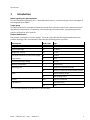
1 Introduction
Notes regarding this documentation
This documentation (EMCA-EC-DIO-…) describes the functions, commissioning and error messages of
the integrated drive EMCA.
Target group
This documentation is intended exclusively for technicians trained in control and automation techno-
logy who have experience in installation, commissioning, parameterisation, programming and dia-
gnostics of electrical drive systems.
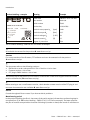
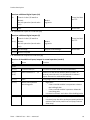
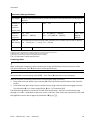
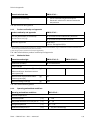
Product identification
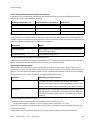
The product is available in various designs. The order code indicates the equipment features (see
product labelling). This documentation describes the following product variants:
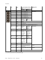
Characteristic Order code Type
Integrated drive EMCA- motor with controller, seriesA
Motor technology EC- EC motor
Flange size, motors 67- 67mm
M- mediumSize (with reference to the overall length
of the motor)
S- short
Nominal operating voltage 1 24 V DC
Electrical connection T Terminal box
I Single-turn absolute encoderMeasuring unit
W Multi-turn absolute measurement system
- without holding brakeBrake
B- with holding brake
Control DIO digital I/O interface
- Standard (IP54)IP protection
S1 IP65
Tab. 1 Product labelling (e.g. EMCA-EC-67-M-1TEB-DIO)
Introduction

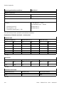
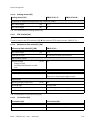
Product labelling – example Meaning Example
Order code EMCA-EC-67-S-1TE-DIO
Part number 8061196
Serial number FN98
Product key 123456789…
Nominal rotary speed n
G
[rpm] 3100
Nominal torque M
N
[Nm] 0.37
Nominal voltage U
N
[V DC] 24
Nominal current I
N
[A] 5.7
123456789...
n
G
: 3100 rpm
M
N
: 0,37 Nm
EMCA-EC-67-S-1TE-DIO
8061196 FN98
U
N
: 24 V DC
I
N
: 5,7 A
IP54
Degree of protection IP54
Tab. 2 Product labelling – EMCA-EC-67-S-1TE-DIO as example
All available documents for the product èwww.festo.com/sp.
Versions
For current versions of the firmware, FCT software and user documentation for the product
èwww.festo.com/sp
This document refers to the following versions:
• EMCA with an order code specified in Tab. 1 Revision 1.0.0 or later
• Firmware version 1.2.0 or later
• FCT plug-in EMCA Version 1.2.0 or later
The Product Key for the product can be used as a search term in the Festo Support Portal to find the
revision of the device (èwww.festo.com/sp)
Before starting to use a new firmware version, check whether a newer version of the FCT plug-in and
new user documentation are available èwww.festo.com/sp.
Service
Consult the regional Festo contact if you have technical problems.
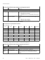
Manufacturing period
In the product labelling, the first 2characters of the serial number indicate the manufacturing date in
encrypted form (Tab. è Product labelling – EMCA-EC-67-S-1TE-DIO as example). The letter specifies
the year of manufacture period the character following it (number or letter) the month of manufacture.
Introduction
8 Festo — EMCA-EC-67-...-DIO — 2020-03d

Manufacturing year
X = 2009 A = 2010 B = 2011 C = 2012 D = 2013 E = 2014 F = 2015
H = 2016 J = 2017 K = 2018 L = 2019 M = 2020 N = 2021 P = 2022
R = 2023 S = 2024 T = 2025 U = 2026 V = 2027 W = 2028 X = 2029
Tab. 3 Year of manufacture (20-year cycle)
Manufacturing month
1 January 2 February 3 March
4 April 5 May 6 June
7 July 8 August 9 September
O October N November D December
Tab. 4 Manufacturing month
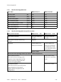
Documentation on the product
The complete documentation for the product includes the following documents:
Identifier Contents
Short documentation
EMCA-…
Brief device and functional description for initial information
Manual
EMCA-EC-DIO-…
Device and functional description
– Assembly
– Installation (pin allocations)
– Drive functions
– Commissioning information
– Error messages
– Technical data
Manual
EMCA-EC-S1-…
Description of the safety function “safe torque off” (Safe torque
off/STO)
Manual
EMCA-EC-C-HP-…
Description of device profile FHPP (Festo Handling and Positioning
Profile)
Help system for the FCT soft-
ware
(Help for the EMCA plug-in)
Online help for the Festo Configuration Tool (FCT) for commission-
ing and parameterisation
Special documentation
EMCA-EC_UL-…
Requirements for operating the product in the USA and Canada in
accordance with certification by Underwriters Laboratories Inc.
(UL)
Tab. 5 Documentation on the product
Introduction
9Festo — EMCA-EC-67-...-DIO — 2020-03d

Further information for the product is available at the Festo Support Portal (èwww.festo.com/sp).
• Operating instructions for Festo configurable electromechanical drives
• Certificates, declaration of conformity
Overview of accessories (catalogue) èwww.festo.com/catalogue
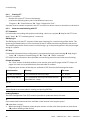
2 Safety and requirements for product use
2.1 Safety
2.1.1 General safety instructions
– Always observe the safety instructions and warnings in the documentation of the product and the
other components.
– Before mounting and installation work, switch off supply voltage and secure it against being
switched on again. Do not switch on the supply voltage until mounting and installation work is
complete.
– Never remove or insert a plug when the motor controller is powered.
– Observe the handling specifications for electrostatically sensitive devices.
– Do not enable the closed-loop controller until the drive has been professionally installed and fully
parameterised.
– Do not carry out repairs on the device. If it is defective, replace the device.
– Do not loosen any screws except for the 4 screws on the housing cover.
WARNING!
Fast rotating motor shaft with high torque.
Contact with the motor shaft can cause burn injuries and abrasions.
• Ensure that the rotating motor shaft and components attached to it cannot be touched.
WARNING!
Risk of injury from touching hot surfaces.
Contact with housing can cause burn injuries. This can frighten people and cause them to act in an
unpredictable manner. This can lead to other forms of secondary damage.
• Avoid unconscious touching of the housing.
• Inform operating and maintenance staff about the possible hazards.
• Before maintenance work: Let the drive cool down to below 40°C.
WARNING!
Gas formation with fire risk.
If cleaning agents come into contact with the hot surface of the drive, gases may be formed and may
ignite.
• Allow the drive cool down to room temperature before starting cleaning.
Safety and requirements for product use
10 Festo — EMCA-EC-67-...-DIO — 2020-03d

2.1.2 Intended use
The product is intended for the actuation and control of electromechanical drives. The integrated elec-
tronics enable regulation of torque (current), rotational speed and position of the mounted drive. The
product is intended for installation in a machine.
Depending on the order, the product contains a motor with holding brake (EMCA-EC-…-…B). The hold-
ing brake is intended to hold the motor position/drive position at standstill.
Use exclusively:
– In perfect technical condition
– In original condition without unauthorised modifications; only the extensions described in the
documentation supplied with the product are permitted
– Within the limits of the product defined by the technical data (è 9.1 Technical data)
– in an industrial environment
The product is intended for use in industrial environments. Outside industrial environments, e.g.in
commercial and mixed-residential areas, actions to suppress interference may have to be taken.
In the event of damage caused by unauthorised manipulation or any form of use other than the inten-
ded use, the warranty will be invalidated and the manufacturer will not be liable for damages.
The product supports the safety function “safe torque off” (Safe torque off/STO).
The safety function STO (Safe torque off) is described in detail in the document EMCA-EC-S1-…. The
safety function STO should only be used in the manner described in this document. Additional inform-
ation è Description of STO safety function, EMCA-EC-S1-….
2.2 Requirements for product use
– Provide the complete product documentation to the following personnel:
– the design engineer and the installer of the machine or system
– the personnel responsible for commissioning
– Keep the documentation somewhere safe throughout the entire product lifecycle.
– Always comply with the specifications of the documentation. The documentation for the other
components and modules (e.g.for the gear unit or axial kit) must also be taken into account.
– Take into consideration the legal regulations for the installation location and also:
– Regulations and standards
– Regulations of the testing organisations and insurers
– National specifications
For correct and safe use of the STO function:
– Observe the additional information in the description EMCA-EC-S1-….
2.2.1 Transport and storage conditions
– Protect the product during transport and storage from excessive stress factors. Excessive stress
factorsinclude:
– mechanical stresses
– impermissible temperatures
– moisture
– aggressive atmospheres
Safety and requirements for product use
11Festo — EMCA-EC-67-...-DIO — 2020-03d

– Store and transport the product in its original packaging. The original packaging offers sufficient
protection from typical stresses.
2.2.2 Technical prerequisites
For correct and safe use of the product:
– Comply with the connection and ambient conditions of the product (è 9.1 Technical data) and all
connected components specified in the technical data. Compliance with the limit values and load
limits permits operation of the product in compliance with the relevant safety regulations.
– Observe the notes and warnings in this documentation.
2.2.3 Training of qualified personnel
The following works may only be carried out by qualified specialists:
– Installation
– Installation
– Commissioning
The qualified personnel must be familiar with the following items:
– electrical control technology
– the applicable regulations for operating safety-related systems
– the applicable regulations for accident prevention and occupational safety
– the documentation for the product:
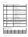
2.2.4 Product conformity and approvals
Standards and test values with which the product complies and fulfils è 9.1 Technical data.
EU Directives relevant to the product è declaration of conformity.
Certificates and the declaration of conformity for this product è www.festo.com/sp
Certain product configurations have Underwriters Laboratories Inc. (UL) certification for the USA and
Canada. These configurations are marked with the following symbol.
Fig. 1
UL Recognized Component Mark for Canada and the United States
Only for connection to a NEC Class 2 supply.
Raccorder Uniqement a un circuit de Class 2.
Rules for observing the UL certification can be found in the separate UL special documentation. The
technical data stated therein take priority. The technical data in this documentation may show values
deviating from this.
Safety and requirements for product use
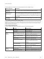
12 Festo — EMCA-EC-67-...-DIO — 2020-03d

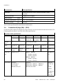
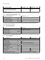
Specified standards
Editions
DIN EN 60068-2-6:2008-10 DIN EN 60068-2-27:2010-02
Tab. 6 Editions of the directives and standards specified in the document
3 Product description
3.1 Product overview
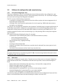
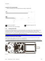
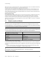
The integrated drive consists of the following components:
– brushless DC motor (EC motor) with
– integrated encoder (single-turn absolute encoder or multi-turn absolute measurement sys-
tem)
– motor shaft for power transmission
– motor flange for coupling and mounting
– device electronics with power, control and regulation electronics
– terminal box with interfaces for electrical installation
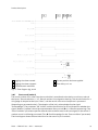
Product description
13Festo — EMCA-EC-67-...-DIO — 2020-03d

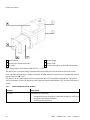
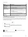
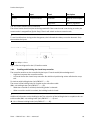
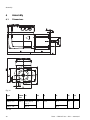
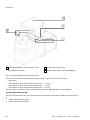
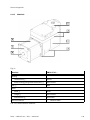
1
Terminal box
2
Housing for device electronics
3
EC motor
4
Motor flange
5
Motor shaft
6
Cover (covering for additional connections)
Fig. 2 Components of the device (EMCA-EC-67-...-DIO)
The device has a compact design. The terminal box provides all of the necessary electrical connec-
tions. The Ethernet interface is freely accessible. All other electrical connections are under the cover of
the terminal box (è Fig.4).
The device can be parameterised and commissioned with FCT via the Ethernet interface. The device
can be controlled via the I/O interface or the Ethernet interface with Modbus TCP and the FHPP device
profile.
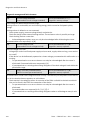
3.1.1 General features of the product
Property Description
EC motor brushless DC motor with:
– integrated encoder (single-turn absolute encoder or multi-turn
absolute measurement system)
– Holding brake (optional)
Product description
14 Festo — EMCA-EC-67-...-DIO — 2020-03d

Property Description
Electronics – Power stage for motor activation and control
– Nominal voltage 24 V DC
– Integrated brake chopper - braking resistor
1)
(accessory) must
be connected externally
– Integrated electronic controls, e.g.with:
– Closed-loop controller for current, velocity and position
control
– Ethernet interface
– I/O interface
– STO safety function (Safe torque off)
– Diagnostic memory
Power supply Common load and logic supply 24 V DC
Commissioning via the Ethernet interface with FCT
Diagnostics LED display, web server, FCT software
Web server software integrated into the device with the following functions:
– display of status information and I/O data
– readout of the diagnostic memory
– uploading and downloading of a parameter file for easy device
replacement
call via web browser (Internet Explorer or Firefox)
1) available separately as an accessory (è www.festo.com/catalogue)
Tab. 7 Overview of EMCA product features
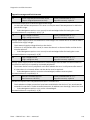
3.1.2 Scope of delivery
Number Component
1 EMCA-… with cover, screws for cover mounting
1 – Brief description EMCA-67-…-DIO
– For product variants with UL identification: special documentation EMCA-EC_UL-…
1 Sealing insert assortment
Tab. 8 EMCA scope of delivery
Below are some examples of the available accessories:
– Axial kits EAMM-A
– Battery box EADA-A-9 (for EMCA-EC-67-1TM)
– Braking resistor CACR-LE2-6-W60
– Seal-SET (seals for axial kit) EADS-F
– Motor flange EAMF-A
– Parallel kits EAMM-U
– Planetary gear unit EMGC
– Assortment of plugs NEKM-C (mating plug for plug connector on the printed circuit board)
Product description
15Festo — EMCA-EC-67-...-DIO — 2020-03d

– Connecting cable for the Ethernet interface NEBC-D12G4-…
– Connecting cable for power supply NEBM-L4G2-…
– Connecting cable for the STO interface NEBM-L5G6-…
– Connecting cable for the I/O interface NEBM-L5G18-…
Current information on accessories è www.festo.com/catalogue
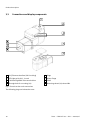
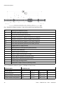
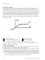
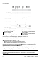
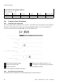
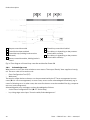
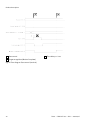
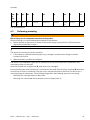
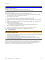
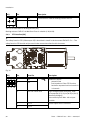
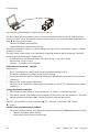
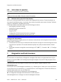
3.1.3 System structure
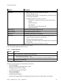
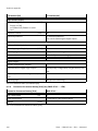
1
Main switch
2
PELV fixed power supply
3
Braking resistor – example
4
Coupling/axial kit – example
5
Reference switch/limit switch – example
(here without)
6
Electromechanical drive – example (here
electric cylinder ESBF)
7
EMCA
8
PC with Festo Configuration Tool (FCT)
9
Higher-order controller (PLC/IPC)
Fig. 3 System structure (example)
Product description
16 Festo — EMCA-EC-67-...-DIO — 2020-03d

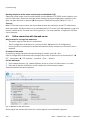
3.2 Software for configuration and commissioning
3.2.1 FCT (Festo Configuration Tool)
The Festo Configuration Tool (FCT) is the Windows-based software platform for configuration, para-
meterisation and commissioning of various Festo components and devices. FCT also allows configura-
tion and commissioning of the integrated drive EMCA.
The FCT consists of the following components:
– a framework as program start and entry point with uniform project and data management for all
supported types of equipment
– one plug-in each for the special requirements of a device type (e.g.EMCA) with the necessary
descriptions and dialogues
The plug-ins are managed and started from the framework. The EMCA plug-in supports performance of
all the steps necessary for configuration, parameterisation and commissioning of the product. Para-
meterisation of the product can be executed offline (without connection to the EMCA) on a PC. This
enables preparation for the actual commissioning, e.g.in the planning office in the project engineer-
ing of a system.
FCT makes possible the following functions, forexample:
– administration of the following data/files via the Ethernet interfaces (online):
– device data (parameterisation)
– firmware file (firmware download)
– manual operation (e.g.jogging, teaching)
– diagnostics
– recording of measurement data
– automatic calculation of the closed-loop controller data for selected Festo motor-gear unit-axis
combinations
– manual precision adjustment of the closed-loop controller data
For further information on commissioning with FCT è 6 Commissioning. Detailed information about
FCT è Help system for the software.
3.2.2 Web server
A web server is integrated into the device. The web server provides access to a dynamic English-lan-
guage website for the device. The website of the web server provides access to the following func-
tions:
– display of the status information of the device (e.g.current position, target position)
– display of the signal statuses of digital I/Os
– readout and display of the diagnostic memory
– upload (Upload) of a parameter file - e.g.to save current settings on the PC
– download (Download) of a parameter file - e.g.to restore settings
– activation of LED flashing for visual identification of the device
In the factory setting, the DHCP server (DHCP stands for Dynamic Host Configuration Protocol) of the
device is activated and the device has the following IP address: 192.168.178.1.
Product description
17Festo — EMCA-EC-67-...-DIO — 2020-03d

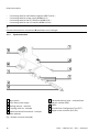
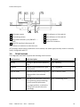
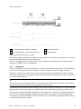
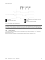
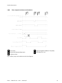
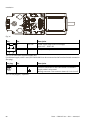
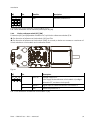
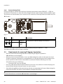
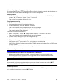
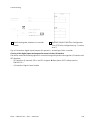
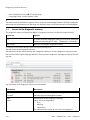
3.3 Connections and display components
1
[X1]: Ethernet interface (M12 bushing)
2
LED light guide (6x) - 2 used
3
Cable throughfeed of the terminal box
4
Through-hole for mounting (4x)
5
Plugs
6
Motor flange
7
Shaft
8
Mounting thread (4x) thread M4
Fig. 4 Control section and connections
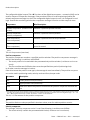
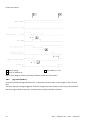
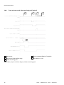
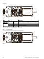
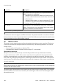
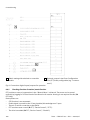
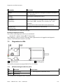
The following plugs are below the cover:
Product description
18 Festo — EMCA-EC-67-...-DIO — 2020-03d

1
[X4]: power supply
2
[X5]: braking resistor
3
[X10]: external battery (only EMCAEC -...-
1TM)
4
[X6]: STO interface (safe torque off)
5
[X7]: reference or limit switch 1
6
[X8]: reference or limit switch 2
7
[X9]: I/O interface
8
central FU connection
Fig. 5 Electrical connections under the cover
[X7] and [X8]: switch function (reference or limit switch) and switch type (normally closed or normally
open), configurable with FCT
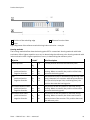
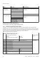
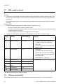
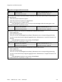
3.4 Drive functions
The integrated drive EMCA supports the following drive functions.
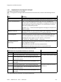
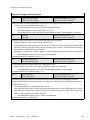
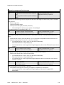
Drive functions Brief description èChapter
Homing Homing to determine the reference
point
è 3.4.2 Homing
Jog Mode Manual control of the drive in posi-
tioning mode
è 3.4.3 Jog Mode
Teach-in mode Save the current position (e.g.as a
target position in the selected
record)
è 3.4.4 Teach-in mode
Positioning mode The EMCA calculates the positioning
curve (point-to-point positioning)
from the specified parameters
(e.g.target position, acceleration,
velocity) and controls the motor
accordingly.
è 3.4.5 Positioning mode
Product description
19Festo — EMCA-EC-67-...-DIO — 2020-03d

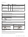
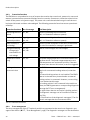
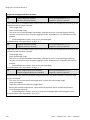
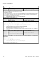
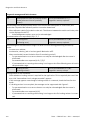
Drive functions Brief description èChapter
Velocity mode Processing of tasks with velocity
setpoint values; the velocity regulat-
or and the current regulator process
deviation between the “velocity
setpoint” and the “actual value for
rotational speed”.
è 3.4.6 Velocity mode
Force/torque mode The current regulator processes the
deviation between the setpoint
value and the actual value for cur-
rent.
è 3.4.7 Force/torque mode
Tab. 9 Drive functions
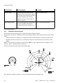
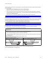
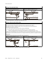
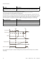
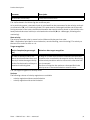
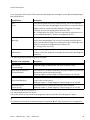
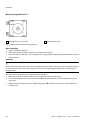
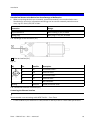
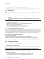
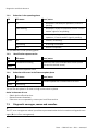
3.4.1 Dimension reference system
All drive functions are based upon a uniform dimension reference system.
The direction of rotation is defined in the factory setting as follows (view toward the face of the motor
shaft):
– Positive direction of rotation (+) corresponds to the clockwise direction of rotation of the motor.
– Negative direction of rotation (–) corresponds to the anti-clockwise direction of rotation of the
motor.
With FCT, the direction of rotation can be adjusted (èFCT, page "Application Data", Register "Envir-
onment", option "Inverse Rotation Polarity").
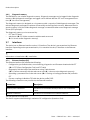
Example: rotary drives with limited positioning range
Fig. 6 Dimension reference system - rotary drives with limited positioning range
Product description
20 Festo — EMCA-EC-67-...-DIO — 2020-03d
La pagina sta caricando ...
La pagina sta caricando ...
La pagina sta caricando ...
La pagina sta caricando ...
La pagina sta caricando ...
La pagina sta caricando ...
La pagina sta caricando ...
La pagina sta caricando ...
La pagina sta caricando ...
La pagina sta caricando ...
La pagina sta caricando ...
La pagina sta caricando ...
La pagina sta caricando ...
La pagina sta caricando ...
La pagina sta caricando ...
La pagina sta caricando ...
La pagina sta caricando ...
La pagina sta caricando ...
La pagina sta caricando ...
La pagina sta caricando ...
La pagina sta caricando ...
La pagina sta caricando ...
La pagina sta caricando ...
La pagina sta caricando ...
La pagina sta caricando ...
La pagina sta caricando ...
La pagina sta caricando ...
La pagina sta caricando ...
La pagina sta caricando ...
La pagina sta caricando ...
La pagina sta caricando ...
La pagina sta caricando ...
La pagina sta caricando ...
La pagina sta caricando ...
La pagina sta caricando ...
La pagina sta caricando ...
La pagina sta caricando ...
La pagina sta caricando ...
La pagina sta caricando ...
La pagina sta caricando ...
La pagina sta caricando ...
La pagina sta caricando ...
La pagina sta caricando ...
La pagina sta caricando ...
La pagina sta caricando ...
La pagina sta caricando ...
La pagina sta caricando ...
La pagina sta caricando ...
La pagina sta caricando ...
La pagina sta caricando ...
La pagina sta caricando ...
La pagina sta caricando ...
La pagina sta caricando ...
La pagina sta caricando ...
La pagina sta caricando ...
La pagina sta caricando ...
La pagina sta caricando ...
La pagina sta caricando ...
La pagina sta caricando ...
La pagina sta caricando ...
La pagina sta caricando ...
La pagina sta caricando ...
La pagina sta caricando ...
La pagina sta caricando ...
La pagina sta caricando ...
La pagina sta caricando ...
La pagina sta caricando ...
La pagina sta caricando ...
La pagina sta caricando ...
La pagina sta caricando ...
La pagina sta caricando ...
La pagina sta caricando ...
La pagina sta caricando ...
La pagina sta caricando ...
La pagina sta caricando ...
La pagina sta caricando ...
La pagina sta caricando ...
La pagina sta caricando ...
La pagina sta caricando ...
La pagina sta caricando ...
La pagina sta caricando ...
La pagina sta caricando ...
La pagina sta caricando ...
La pagina sta caricando ...
La pagina sta caricando ...
La pagina sta caricando ...
La pagina sta caricando ...
La pagina sta caricando ...
La pagina sta caricando ...
La pagina sta caricando ...
La pagina sta caricando ...
La pagina sta caricando ...
La pagina sta caricando ...
La pagina sta caricando ...
La pagina sta caricando ...
La pagina sta caricando ...
La pagina sta caricando ...
La pagina sta caricando ...
La pagina sta caricando ...
La pagina sta caricando ...
La pagina sta caricando ...
La pagina sta caricando ...
La pagina sta caricando ...
La pagina sta caricando ...
La pagina sta caricando ...
La pagina sta caricando ...
La pagina sta caricando ...
La pagina sta caricando ...
La pagina sta caricando ...
La pagina sta caricando ...
La pagina sta caricando ...
La pagina sta caricando ...
La pagina sta caricando ...
La pagina sta caricando ...
La pagina sta caricando ...
La pagina sta caricando ...
La pagina sta caricando ...
La pagina sta caricando ...
La pagina sta caricando ...
La pagina sta caricando ...
-
 1
1
-
 2
2
-
 3
3
-
 4
4
-
 5
5
-
 6
6
-
 7
7
-
 8
8
-
 9
9
-
 10
10
-
 11
11
-
 12
12
-
 13
13
-
 14
14
-
 15
15
-
 16
16
-
 17
17
-
 18
18
-
 19
19
-
 20
20
-
 21
21
-
 22
22
-
 23
23
-
 24
24
-
 25
25
-
 26
26
-
 27
27
-
 28
28
-
 29
29
-
 30
30
-
 31
31
-
 32
32
-
 33
33
-
 34
34
-
 35
35
-
 36
36
-
 37
37
-
 38
38
-
 39
39
-
 40
40
-
 41
41
-
 42
42
-
 43
43
-
 44
44
-
 45
45
-
 46
46
-
 47
47
-
 48
48
-
 49
49
-
 50
50
-
 51
51
-
 52
52
-
 53
53
-
 54
54
-
 55
55
-
 56
56
-
 57
57
-
 58
58
-
 59
59
-
 60
60
-
 61
61
-
 62
62
-
 63
63
-
 64
64
-
 65
65
-
 66
66
-
 67
67
-
 68
68
-
 69
69
-
 70
70
-
 71
71
-
 72
72
-
 73
73
-
 74
74
-
 75
75
-
 76
76
-
 77
77
-
 78
78
-
 79
79
-
 80
80
-
 81
81
-
 82
82
-
 83
83
-
 84
84
-
 85
85
-
 86
86
-
 87
87
-
 88
88
-
 89
89
-
 90
90
-
 91
91
-
 92
92
-
 93
93
-
 94
94
-
 95
95
-
 96
96
-
 97
97
-
 98
98
-
 99
99
-
 100
100
-
 101
101
-
 102
102
-
 103
103
-
 104
104
-
 105
105
-
 106
106
-
 107
107
-
 108
108
-
 109
109
-
 110
110
-
 111
111
-
 112
112
-
 113
113
-
 114
114
-
 115
115
-
 116
116
-
 117
117
-
 118
118
-
 119
119
-
 120
120
-
 121
121
-
 122
122
-
 123
123
-
 124
124
-
 125
125
-
 126
126
-
 127
127
-
 128
128
-
 129
129
-
 130
130
-
 131
131
-
 132
132
-
 133
133
-
 134
134
-
 135
135
-
 136
136
-
 137
137
-
 138
138
-
 139
139
-
 140
140


Festo 8061196 Operating Instructions Manual
- Tipo
- Operating Instructions Manual
in altre lingue
- English: Festo 8061196
Documenti correlati
-
Festo DYSS Manuale utente
-
Festo CMMO-ST-xxx-DIOP series Original Instructions Manual
-
-
-
Festo SPC200 Series User Instructions
-
-
-
-
-
Festo 1451384 Operating Instructions Manual
Altri documenti
-
Snap-On TECHANGLE Manuale utente
-
SICK Flexi Gateway GPNT1 Expansion module - gateway Istruzioni per l'uso
-
-
Hitachi ATW-RTU-02 Istruzioni per l'uso
-
ABB ACS850 series Quick Start Up Manual
-
Pepperl+Fuchs UMB800-18H40-I-2M Istruzioni per l'uso
-
ABB REL650 series Applications Manual
-
WAGO Fieldbus Coupler Modbus TCP M12 Manuale utente
-
McIntosh MA9000 Manuale del proprietario