Nice Automation FE, FEP, FI and BF Manuale del proprietario
- Tipo
- Manuale del proprietario

V. 003
I
ANLEITUNGS-
HEFT
INSTRUCTIONS
MANUAL
E
D
LIVRET
D’INSTRUCTIONS
MANUAL DE
INSTRUCCIONES
Barrière a
rayons
infrarouges
selon les normes
UNI 8612
séries:
FE - FEP
FI - BF
Infrarot -
Lichtschranke
gemäß der
Norm UNI 8612
serie:
FE - FEP
FI - BF
Barrera
con rayos
infrarrojos
segùn normas
UNI 8612
series:
FE - FEP
FI - BF
MANUALE
ISTRUZIONI
Barriera
all' infrarosso
a norme
UNI 8612
serie:
FE - FEP
FI - BF
Infrared barrier
according to
UNI 8612
series:
FE - FEP
FI - BF
GB
F
QUESTO LIBRETTO È DESTINATO SOLO ALL'INSTALLATORE.
L'installazione dovrà essere effettuata solamente da personale professionalmente qualificato in conformità a quanto previsto dalla legge n°
46 del 5 marzo 1990 e successive modifiche ed integrazioni e nel pieno rispetto delle norme UNI 8612.

2
!!
!!
I
1° coppia
1st pair
1er couple
1. Paar
1ª pareja
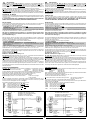
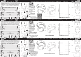
- Installazzione con alimentazione continua
- Installation with direct current
- Installation avec alimentation continue
- Installation mit Gleichstrom
- Instalación con corriente continua
Fig. 2
- Installazzione con alimentazione alternata
- Installation with alternating current
- Installation avec alimentation alternée
- Installation mit Wechselstrom
- Instalación con corriente alterna.
Fig. 1
Centrale
Central
Centrale
Steuereinheit
Central
2° coppia
2nd pair
2ème couple
2. Paar
2ª pareja
1° coppia
1st pair
1er couple
1. Paar
1ª pareja
2° coppia
2nd pair
2ème couple
2. Paar
2ª pareja
Centrale
Central
Centrale
Steuereinheit
Central
GB
DESCRIZIONE:
I dispositivi della serie
FE - FEP - FI - BF sono composti da un trasmettitore TX e da un
ricevitore
RX. La barriera si realizza tramite l'emissione di luce all'infrarosso modulato.
Grazie alle sue dimensioni ridotte
FE - FEP - BF può essere installata a parete senza più
necessità di fori o scanalature, non ha bisogno di alcuna regolazione di centratura. Il
perfetto allineamento della barriera viene visualizzato da un led sul ricevitore.
FI è stata disegnata per poter essere incassata a muro e effettuare le regolazioni di
allineamento con grande facilità grazie anche alla disponibilità di 2 test point.
FE - FEP - FI - BF sono state progettate rispettando tutte le normative vigenti (UNI 8612),
il design e i materiali impiegati la rendono particolarmente affidabile e duratura nel tempo.
POSSIBILITÀ DI IMPIEGO
Viene impiegata nei sistemi di allarme interni o esterni, per la protezione di porte e cancelli.
L'impiego e l'uso di questa apparecchiatura deve rispettare rigorosamente le norme di
sicurezza vigenti.
IL COSTRUTTORE NON PUÓ CONSIDERARSI RESPONSABILE PER EVENTUALI
DANNI CAUSATI DA USI IMPROPRI, ERRONEI ED IRRAGIONEVOLI.
INSTALLAZIONE
La nuova generazione di dispositivi dispone di un circuito di sincronismo che permette di
poter montare due coppie anche vicinissime senza che si interferiscano tra di loro.
Per poter usufruire di questa caratteristica:
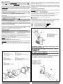
- TAGLIARE il ponticello "A" (fig. 6) su entrambi i
TX.
- ALIMENTARE le due coppie in corrente alternata, invertendo le polarità fra la prima e
la seconda coppia (fig. 1).
Il funzionamento sincronizzato può essere usato anche su una singola coppia, ottenendo
un più preciso funzionamento e un minor consumo di corrente.
N.B.: Nel caso l'alimentazione sia continua (c.c.) la funzione di sincronismo viene
annullata quindi è necessario installare i due ricevitori uno opposto all'altro come
pure i trasmettitori (fig. 2).
Data la elevata potenza del raggio emesso dal trasmettitore, quando la distanza dal
ricevitore é inferiore a 4 - 5 mt possono avvenire dei fenomeni di riflessione con oggetti nelle
vicinanze, compromettendone il corretto funzionamento.
Per risolvere questo problema sono previsti 2 livelli di portata.
1) 15 MT (STANDARD)
2) 30 MT (TAGLIARE IL PONTICELLO "B" SUL RICEVITORE fig. 6).
N.B.: La portata si può ridurre del 50 % in presenza di fenomeni atmosferici: nebbia
pioggia, polvere ecc.
Un'altra caratteristica della nuova generazione é l'alimentazione.
Grazie a un nuovo sistema di stabilizzazione é possibile alimentare i fotodispositivi
indifferentemente con una alimentazione che varia da 12 Vcc/ca a 30 Vcc/ca.
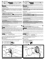
I trasmettitori e i ricevitori dovranno essere fissati sullo stesso asse geometrico e alla stessa
altezza dal suolo, frontalmente.Per togliere il coperchio fare leva con un cacciavite sulla
ferritoia posta in basso (
FE - FI).
Fissare la barriera fig. 3 - 4 - 5.
Effettuare i collegamenti come in fig. 1 o 2.
FE - FEP - BF: alimentare la barriera a 12 - 24 Vcc/ca, se la barriera risulta correttemente
collegata e allineata il led rosso sul ricevitore sarà spento.
FI: alimentare la barriera, effettuare l'allineamento con l'ausilio di un tester posto a 3-5 Vcc
fondo scala: inserire i rispettivi puntali nelle sedi del ricevitore, rispettando la polarità
contrassegnata, agire sulle 3 viti di regolazione sia sul trasmettitore che sul ricevitore fino
ad ottenere la massima tensione sul tester. (valore minimo da ottenere 0,3 Vcc.
Qualora non ci fosse la possibilità di utilizzare un tester, un ulteriore controllo di centratura
può essere visualizzato tramite l'apposito led posto sul ricevitore, il led sarà + o - illuminato
a seconda della centratura, se la barriera risulterà allineata e centrata il led avrà la massima
intensità luminosa.
VERIFICA DI FUNZIONAMENTO
FE - FEP - BF: Interrompere il fascio più volte controllando la commutazione del relé e
l'accensione del led rosso sul ricevitore. - non allineato: LED ROSSO ACCESO
- allineato: LED ROSSO SPENTO
Inserire il frontalino sulla barriera verificando sempre il perfetto funzionamento. Con il filtro
di attenuazione inserito, la barriera deve essere ancora perfettamente funzionante.
Il filtro simula condizioni metereologiche avverse (nebbia, pioggia ecc.).
Togliere quindi il filtro di attenuazione al termine delle verifiche.
FI: interrompere più volte con una mano il fascio. - Il led rosso si spegne.
- Il relé commuta.
Inserire il frontalino sulla barriera, verificando sempre il perfetto funzionamento. Se si
dovesse installare la barriera a distanze superiori ai 30 mt. (fino a 100 mt.) é possibile
inserire una lente nell'apposito incastro (vedi fig. 5).
Per facilitare l’installazione la NICE fornisce gli accessori:
- COF : olonnina in metallo H 50 cm.
FE - FEP
- PCF : piastra di fondazione per colonnina
FE - FEP
- COB : colonnina in metallo H 50 cm.
BF
- PCB : piastra di fondazione per colonnina
BF
- CPI : contenitore plastica a murare
FI
DESCRIPTION:
The devices in the series
FE - FEP - FI - BF are composed of a TX transmitter and an RX
receiver. The barrier is made through the emission of modulated infra-red light. Thanks to
their reduced dimensions,
FE - FEP - BF can be wall mounted without it being necessary
to make any holes or grooves, and it needs no centring adjustment. Perfect alignment of
the barriers can be visualized by a LED on the receiver.
FI has been designed to be recessed in the wall and alignment is adjusted extremely easily,
thanks also to the 2 test points available.
FE - FEP - FI - BF have been designed in conformity with all standards in force (UNI 8612),
their design and the materials used for manufacture mean that they are particularly reliable
and long lasting.
RANGE OF USE
They are used in indoor or outdoor alarm systems, to protect doors and gates. These
devices must be utilized and used in strict compliance with the safety regulations in force.
THE MANUFACTURER CANNOT BE HELD RESPONSIBLE FOR ANY DAMAGE
CAUSED BY IMPROPER, ERRONEOUS OR UNREASONABLE USE.
INSTALLATION
The new generation of devices are equipped with a synchronous circuit which allows two
pairs to be installed extremely close to each other without any interference between them.
To take advantage of this facility:
CUT the jumper “A” (fig. 6) on both
TX;
SUPPLY the two pairs with alternating current, inverting the polarity between the first
and the second pair (fig.1).
Synchronous operation may also be used on a single pair, in order to obtain more accurate
operation and consume less power.
N.B.: In the event of direct current (DC) supply synchronous operation is cancelled
and it is therefore necessary to install the two receivers and transmitters on opposite
sides from each other (fig. 2).
As the beam emitted by the transmitter is extremely powerful, when there is a distance of
less than 4-5 m from the receiver correct operation could be affected by phenomena of
reflection with nearby objects.
To solve this problem 2 levels of range are possible:
1) 15 M (STANDARD)
2) 30 M (CUT JUMPER “B” ON THE RECEIVER - FIG. 6)
N.B.: Range may be reduced by 50% by bad weather conditions, such as fog, rain,
dust, etc.
Another feature of the new generation is the power supply.
Thanks to a new stablisation system, it is possible to supply the photoelectric devices
indifferently with a voltage which varies from 12V DC/AC to 30V DC/AC.
The transmitter and receiver must be fixed on the same geometrical axis and at the same
height from the ground, opposite each other. To remove the cover insert a screwdriver into
the slot positioned on the lower part and exert pressure (
FE - FI).
Fix the barrier - figs. 3, 4, 5.
Make the connections as in figs. 1 or 2.
FE - FEP - BF: supply the barrier with 12 - 24V DC/AC; if the barrier is correctly connected
and aligned the red LED on the receiver will be off.
FI: supply the barrier, align with the aid of a tester positioned at 3-5V DC bottom of scale:
introduce the corresponding prods in the receiver seats, observing the polarity marked, turn
the 3 adjustment screws on both the transmitter and the receiver until maximum voltage is
obtained on the tester (minimum value to obtain 0.3V DC).
Should it not be possible to use a tester, centring can be checked by observing the specific
LED on the receiver: the LED will be lit to a greater or lesser extent according to the level
of centring, if the barrier is aligned and centred the LED will be brightly lit.
CHECKING OPERATION
FE - FEP - BF: Interrupt the beam several times checking that the relay switches over and
that the red LED on the receiver lights up.
not aligned: RED LED ON
aligned: RED LED OFF
Fit the front to the barrier, checking that it still operates perfectly. With the attenuation filter
fitted, the barrier must still function perfectly.
The filter simulates bad weather conditions (fog, rain, etc.).
Remove the attenuation filter after checking.
FI: interrupt the beam several times with your hand: the red LED is switched off;
the relay switches over.
Fit the front to the barrier, checking that it still operates perfectly.
If the barrier is installed at a distance of over 30 m (up to 100 m) a lens may be fitted in the
specific housing (see fig. 5).
NICE supplies the following accessories to facilitate installation:
- COF : metal column H 50 cm
FE - FEP
- PCF : base plate for column
FE - FEP
- COB : metal column H 50 cm
BF
- PCB : base plate for column
BF
- CPI : masonry plastic container
FI
12÷24 Vcc
12÷24 Vca
La pagina si sta caricando...
La pagina si sta caricando...

5
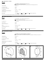
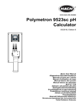
CARATTERISTICHE TECNICHE
RICEVITORE
PORTATA
ALIMENTAZIONE
LUNGHEZZA D'ONDA
FREQUENZA INFRAROSSO
ASSORBIMENTO
TEMPERATURA DI FUNZIONAMENTO
PORTATA RELE'
DIMENSIONI
I
La NICE spa si riserva il diritto di apportare modifiche in qualsiasi momento e senza preavviso alcuno.
FEP FE
BF
38
64
77
32
77
54
84
27
64
: 15mt STANDARD - 30mt tagliando l'apposito ponticello sul RX
:
FI- estendibile a 100 mt con apposita lente LE
: La portata si può ridurre del 50% in presenza di fenomeni atmosferici: nebbia, pioggia, polvere ecc.
: 12÷24 Vcc-ca
: 880 nm.
: 540 Hz
: RX 20 mA - TX 35 mA
: - 20° + 70° C
: 1 A MAX 24 V.
: 77X64X32
FE - 77X64X38 FEP - 54X84X27 BF - 80X77X64 FI (la parte incassabile: ø 60)
THECNICAL CHARACTERISTICS
RECEIVER
RANGE: : 15 m STANDARD - 30 m by cutting the specific jumper on RX
: FI: extensible to 100 m with specific LE lens
: Range can be reduced to 50% in bad weather conditions: fog, rain, dust, etc.
POWER SUPPLY : 12 to 24V DC/AC
WAVE LENGTH : 880 Nm
INFRA-RED FREQUENCY : 540 Hz
INPUT : RX 20 mA - TX 35 mA
OPERATING TEMPERATURE : - 20°C to 70°C
RELAY OUTPUT : 1A max 24V
DIMENSIONS: : 77X64X32
FE - 77X64X38 FEP - 54X84X27 BF - 80X77X64 FI (recessing part: diam. 60)
NICE spa reserves the right to make modifications at any time without prior notice.
CARATTERISTIQUES TECNIQUES
RECEPTEUR
PORTEE:
ALIMENTATION
LONGUEUR D’ONDE
FREQUENCE INFRAROUGE
ABSORPTION
TEMPERATURE DE FONCTIONNEMENT
PORTEE RELAIS
DIMENSIONS
F
: 15 m standard - 30 m en coupant le pontet prévu à cet effet sur RX
: FI - peut s’étendre à 100 m avec la lentille LE prévue à cet effet
: La portée peut se réduire de 50% en présence de phénomènes atmosphériques: brouillard, pluie, poussières, etc.
: 12÷24 Vcc-ca
: 880 nm.
: 540 Hz
: RX 20 mA - TX 35 mA
: - 20° + 70° C
: 1 A MAX 24 V.
: 77X64X32
FE - 77X64X38 FEP - 54X84X27 BF - 80X77X64 FI (la partie encastrable: Ø 60)
La ste NICE spa se reserve le droit d'apporter toutes modifications a tous moments sans aucun preavis.
GB

THECNICAL CHARACTERISTICS
EMPFÄNGER
D
A termini di legge ci riserviamo la proprietà di questo manuale con divieto di riprodurlo o di renderlo comunque noto a terzi
o a ditte concorrenti senza nostra autorizzazione.
Die Firma NICE spa behält sich das Recht vor, jederzeit und ohne Vorankündigung Veränderungen durchzuführen.
CARACTERISTICAS TÉCNICAS
RECEPTOR
ALCANCE : 15 m. estándar - 30 m. cortando el correspondiente conector puente en el RX.
:
FI extensible a 100 m con la correspondiente lente LE.
: El alcance se puede reducir al 50% en presencia de fenómenos atmosféricos como niebla, lluvia, polvo, etc.
ALIMENTACIÓN : 12 - 24 Vcc-ca
LONGITUD DE ONDA : 880 nm.
FRECUENCIA INFRARROJO : 540 Hz.
ABSORCIÓN : RX 20 mA - TTX 35 mA.
TEMPERATURA DE FUNCIONAMIENTO : -20 +70 ºC.
ALCANCE RELÉ : A MAX 24 V.
DIMENSIONES : 77x64x32
FE - 77x64x38 FEP - 54x84x27 BF - 80x77x64 FI (parte empotrable: 60).
E
FI
CPI
51
77
30
64
50
60
LEISTUNG
SPEISUNG
WELLENLÄNGE
INFRAROTFREQUENZ
LEISTUNGSAUFNAHME
BETRIEBSTEMPERATUR
LEISTUNG RELAIS
ABMESSUNGEN
: 15 m Standard - 30 m bei Durchtrennen der entsprechenden Brücke am RX
:
FI - ausdehnbar auf 100 m mit entsprechender Linse LE
: Die Leistung kann sich bei atmosphärischen Phänomenen wie Nebel, Regen, Staub usw. um 50 % reduzieren.
: 12 - 24 Vdc - Vac
: 880 nm
: 540 Hz
: RX 20 mA - TX 35 mA
: - 20°C bis + 70°C
: 1 A max. 24 V
: 77x64x32
FE - 77x64x38 FEP - 54x84x27 BF - 80x77x64 FI (Einbauteil Ø 60)
NICE spa se reserva el derecho de aportar modificaciones en cualquier momento y sin aviso previo.
82
70
65
carta riciclata 100% recycled paper 100% papier recycle 100% 100% Altpapier 100% papel reciclado
ISTFE - Cod. 4854 -
CENTRO STAMPA - Oderzo (TV)
NICE SPA - Via Pezza Alta, 13 - Z.I. di Rustignè
31046 ODERZO - TV - ITALY
Tel. 0422 853838 - Fax. 0422 853585
http://www.niceforyou.com - email: [email protected]
-
 1
1
-
 2
2
-
 3
3
-
 4
4
-
 5
5
-
 6
6


Nice Automation FE, FEP, FI and BF Manuale del proprietario
- Tipo
- Manuale del proprietario
in altre lingue
Documenti correlati
Altri documenti
-
 quiko QK-FTPO Manuale utente
-
PRASTEL FOTO35SDE Manuale utente
-
Nikon EDG VR Fieldscope Manuale utente
-
WIKA IL-10 Istruzioni per l'uso
-
-
Micro Motion Misuratore a 9-fili preparazione e Manuale del proprietario
-
-
-
 Hach Polymetron 9523sc pH Basic User Manual
-
Prusa3D SL1 Manuale utente

