
Mellanox Technologieswww.mellanox.com
Mellanox 1U EDR 100Gb/s
InfiniBand Switch Systems and IB
Router
Hardware User Manual
Models: SB7700/SB7790/SB7800/SB7890/SB7780
Rev. 1.7

Mellanox Technologies
350 Oakmead Parkway Suite 100
Sunnyvale, CA 94085
U.S.A.
www.mellanox.com
Tel: (408) 970-3400
Fax: (408) 970-3403
© Copyright 2017. Mellanox Technologies Ltd . All Rights Reserved .
Mellanox®, Mellanox logo, Accelio®, BridgeX®, CloudX logo, CompustorX®, Connect-IB®, ConnectX®,
CoolBox®, CORE-Direct®, EZchip®, EZchip logo, EZappliance®, EZdesign®, EZdriver®, EZsystem®,
GPUDirect®, InfiniHost®, InfiniBridge®, InfiniScale®, Kotura®, Kotura logo, Mellanox CloudRack® , Mellanox
CloudXMellanox® , Mellanox Federal Systems®, Mellanox HostDirect® , Mellanox Multi-Host® , Mellanox Open
Ethernet®, Mellanox OpenCloud® , Mellanox OpenCloud Logo® , Mellanox PeerDirect® , Mellanox ScalableHPC® ,
Mellanox StorageX® , Mellanox TuneX® , Mellanox Connect Accelerate Outperform logo , Mellanox Virtual Modular
Switch®, MetroDX®, MetroX®, MLNX-OS®, NP-1c®, NP-2®, NP-3®, Open Ethernet logo, PhyX®, PlatformX®,
PSIPHY®, SiPhy®, StoreX®, SwitchX®, Tilera®, Tilera logo, TestX®, TuneX®, The Generation of Open Ethernet
logo, UFM®, Unbreakable Link® , Virtual Protocol Interconnect®, Voltaire® and Voltaire logo are registered
trademarks of Mellanox Technologies , Ltd.
All other trademarks are property of their respective owners .
For the most updated list of Mellanox trademarks, visit http://www.mellanox.com/page/trademarks
NOTE:
THIS HARDWARE, SOFTWARE OR TEST SUITE PRODUCT (“PRODUCT (S)”) AND ITS RELATED
DOCUMENTATION ARE PROVIDED BY MELLANOX TECHNOLOGIES “AS-IS” WITH ALL FAULTS OF ANY
KIND AND SOLELY FOR THE PURPOSE OF AIDING THE CUSTOMER IN TESTING APPLICATIONS THAT
USE THE PRODUCTS IN DESIGNATED SOLUTIONS. THE CUSTOMER'S MANUFACTURING TEST
ENVIRONMENT HAS NOT MET THE STANDARDS SET BY MELLANOX TECHNOLOGIES TO FULLY
QUALIFY THE PRODUCT(S) AND/OR THE SYSTEM USING IT. THEREFORE, MELLANOX TECHNOLOGIES
CANNOT AND DOES NOT GUARANTEE OR WARRANT THAT THE PRODUCTS WILL OPERATE WITH THE
HIGHEST QUALITY. ANY EXPRESS OR IMPLIED WARRANTIES, INCLUDING, BUT NOT LIMITED TO, THE
IMPLIED WARRANTIES OF MERCHANTABILITY, FITNESS FOR A PARTICULAR PURPOSE AND
NONINFRINGEMENT ARE DISCLAIMED. IN NO EVENT SHALL MELLANOX BE LIABLE TO CUSTOMER OR
ANY THIRD PARTIES FOR ANY DIRECT, INDIRECT, SPECIAL, EXEMPLARY, OR CONSEQUENTIAL
DAMAGES OF ANY KIND (INCLUDING, BUT NOT LIMITED TO, PAYMENT FOR PROCUREMENT OF
SUBSTITUTE GOODS OR SERVICES; LOSS OF USE, DATA, OR PROFITS; OR BUSINESS INTERRUPTION)
HOWEVER CAUSED AND ON ANY THEORY OF LIABILITY, WHETHER IN CONTRACT , STRICT LIABILITY,
OR TORT (INCLUDING NEGLIGENCE OR OTHERWISE) ARISING IN ANY WAY FROM THE USE OF THE
PRODUCT (S) AND RELATED DOCUMENTATION EVEN IF ADVISED OF THE POSSIBILITY OF SUCH
DAMAGE.
Rev. 1.7Document Number: MLNX-15-4668 2Mellanox Technologies

Rev. 1.7 3Mellanox Technologies
List of Tables
Revision History . . . . . . . . . . . . . . . . . . . . . . . . . . . . . . . . . . . . . . . . . . . . . . . . . . 7
About this Manual . . . . . . . . . . . . . . . . . . . . . . . . . . . . . . . . . . . . . . . . . . . . . . . . 8
Chapter 1 Introduction to Mellanox SB77X0/SB78X0 Switch Systems and SB7780
InfinBand Router . . . . . . . . . . . . . . . . . . . . . . . . . . . . . . . . . . . . . . . 10
1.1 Overview . . . . . . . . . . . . . . . . . . . . . . . . . . . . . . . . . . . . . . . . . . . . . . . . . . . . 10
1.2 Speed and Switching . . . . . . . . . . . . . . . . . . . . . . . . . . . . . . . . . . . . . . . . . . 11
1.3 Management Interfaces and FRUs . . . . . . . . . . . . . . . . . . . . . . . . . . . . . . . 11
1.4 Features. . . . . . . . . . . . . . . . . . . . . . . . . . . . . . . . . . . . . . . . . . . . . . . . . . . . . 12
1.5 Certifications. . . . . . . . . . . . . . . . . . . . . . . . . . . . . . . . . . . . . . . . . . . . . . . . . 12
1.6 Ordering Information . . . . . . . . . . . . . . . . . . . . . . . . . . . . . . . . . . . . . . . . . . 12
Chapter 2 Installation . . . . . . . . . . . . . . . . . . . . . . . . . . . . . . . . . . . . . . . . . . . . 14
2.1 Safety Warnings . . . . . . . . . . . . . . . . . . . . . . . . . . . . . . . . . . . . . . . . . . . . . . 14
2.2 Air Flow . . . . . . . . . . . . . . . . . . . . . . . . . . . . . . . . . . . . . . . . . . . . . . . . . . . . . 15
2.3 Package Contents . . . . . . . . . . . . . . . . . . . . . . . . . . . . . . . . . . . . . . . . . . . . . 17
2.4 Mounting Options . . . . . . . . . . . . . . . . . . . . . . . . . . . . . . . . . . . . . . . . . . . . 18
2.4.1 19” Systems Mounting - Static Rail-Kit . . . . . . . . . . . . . . . . . . . . . . . . . . . . 18
2.4.2 19” Systems Mounting- Telescopic Rail-Kit. . . . . . . . . . . . . . . . . . . . . . . . . 23
2.5 Cable Installation . . . . . . . . . . . . . . . . . . . . . . . . . . . . . . . . . . . . . . . . . . . . . 29
2.6 Initial Power On . . . . . . . . . . . . . . . . . . . . . . . . . . . . . . . . . . . . . . . . . . . . . . 30
2.7 System Bring-Up of Managed Systems . . . . . . . . . . . . . . . . . . . . . . . . . . . . 31
2.7.1 Configuring Network Attributes. . . . . . . . . . . . . . . . . . . . . . . . . . . . . . . . . . 31
2.7.2 Remote Connection . . . . . . . . . . . . . . . . . . . . . . . . . . . . . . . . . . . . . . . . . . . 35
2.8 FRU Replacements . . . . . . . . . . . . . . . . . . . . . . . . . . . . . . . . . . . . . . . . . . . . 36
2.8.1 Power Supply. . . . . . . . . . . . . . . . . . . . . . . . . . . . . . . . . . . . . . . . . . . . . . . . . 36
2.8.2 Fans . . . . . . . . . . . . . . . . . . . . . . . . . . . . . . . . . . . . . . . . . . . . . . . . . . . . . . . . 37
Chapter 3 Software Management . . . . . . . . . . . . . . . . . . . . . . . . . . . . . . . . . . 39
3.1 InfiniBand Subnet Manager . . . . . . . . . . . . . . . . . . . . . . . . . . . . . . . . . . . . . 39
3.2 Fabric Inspector (Diagnostics) . . . . . . . . . . . . . . . . . . . . . . . . . . . . . . . . . . . 39
3.3 Upgrading Software (on Managed Systems) . . . . . . . . . . . . . . . . . . . . . . . 40
3.4 Updating Firmware on Externally Managed Systems . . . . . . . . . . . . . . . . 40
3.4.1 Updating Firmware In-band (Typical) . . . . . . . . . . . . . . . . . . . . . . . . . . . . . 40
Chapter 4 Interfaces . . . . . . . . . . . . . . . . . . . . . . . . . . . . . . . . . . . . . . . . . . . . . 42
4.1 Supported Interfaces . . . . . . . . . . . . . . . . . . . . . . . . . . . . . . . . . . . . . . . . . . 42
4.1.1 Data Interfaces . . . . . . . . . . . . . . . . . . . . . . . . . . . . . . . . . . . . . . . . . . . . . . . 42
4.1.2 Speed . . . . . . . . . . . . . . . . . . . . . . . . . . . . . . . . . . . . . . . . . . . . . . . . . . . . . . . 42

Rev. 1.74 Mellanox Technologies
4.1.3 RS232 (Console). . . . . . . . . . . . . . . . . . . . . . . . . . . . . . . . . . . . . . . . . . . . . . . 43
4.1.4 Management . . . . . . . . . . . . . . . . . . . . . . . . . . . . . . . . . . . . . . . . . . . . . . . . . 43
4.1.5 USB . . . . . . . . . . . . . . . . . . . . . . . . . . . . . . . . . . . . . . . . . . . . . . . . . . . . . . . . . 43
4.1.6 Reset Button . . . . . . . . . . . . . . . . . . . . . . . . . . . . . . . . . . . . . . . . . . . . . . . . . 44
4.2 LEDs . . . . . . . . . . . . . . . . . . . . . . . . . . . . . . . . . . . . . . . . . . . . . . . . . . . . . . . . 44
4.2.1 LED Notifications . . . . . . . . . . . . . . . . . . . . . . . . . . . . . . . . . . . . . . . . . . . . . . 44
4.3 Inventory Pull-out Tab . . . . . . . . . . . . . . . . . . . . . . . . . . . . . . . . . . . . . . . . . 50
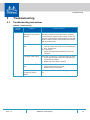
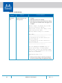
Chapter 5 Troubleshooting. . . . . . . . . . . . . . . . . . . . . . . . . . . . . . . . . . . . . . . . 51
5.1 Troubleshooting Instructions. . . . . . . . . . . . . . . . . . . . . . . . . . . . . . . . . . . . 51
Chapter 6 Specifications . . . . . . . . . . . . . . . . . . . . . . . . . . . . . . . . . . . . . . . . . . 53
6.1 SB77X0/SB78X0 Series . . . . . . . . . . . . . . . . . . . . . . . . . . . . . . . . . . . . . . . . . 53
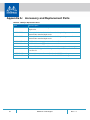
Appendix A Accessory and Replacement Parts . . . . . . . . . . . . . . . . . . . . . . . 54
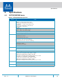
Appendix B Thermal Threshold Definitions . . . . . . . . . . . . . . . . . . . . . . . . . . 55
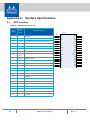
Appendix C Interface Specifications . . . . . . . . . . . . . . . . . . . . . . . . . . . . . . . . 56
C.1 QSFP Interface . . . . . . . . . . . . . . . . . . . . . . . . . . . . . . . . . . . . . . . . . . . . . 56
C.2 RJ-45 CONSOLE and I²C Interface . . . . . . . . . . . . . . . . . . . . . . . . . . . . . . 58
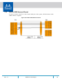
C.3 RJ45 to DB9 Harness Pinout . . . . . . . . . . . . . . . . . . . . . . . . . . . . . . . . . . 59
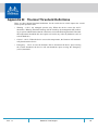
Appendix D Disassembly and Disposal . . . . . . . . . . . . . . . . . . . . . . . . . . . . . . 60
D.1 Disassembly Procedure . . . . . . . . . . . . . . . . . . . . . . . . . . . . . . . . . . . . . . 60
D.2 Disposal . . . . . . . . . . . . . . . . . . . . . . . . . . . . . . . . . . . . . . . . . . . . . . . . . . 60
Appendix E Safety Warnings (Multiple Languages) . . . . . . . . . . . . . . . . . . . . 61
E.1 Nordic Countries Notices . . . . . . . . . . . . . . . . . . . . . . . . . . . . . . . . . . . . 61
E.2 Installation Safety Warnings (English) . . . . . . . . . . . . . . . . . . . . . . . . . . 61
E.3 תירבע) הנקתהב תוחיטב תורהזא) . . . . . . . . . . . . . . . . . . . . . . . . . . . . . 64
E.4 安裝安全性警告 (Chinese) . . . . . . . . . . . . . . . . . . . . . . . . . . . . . . . . . . 68
E.5 Avertissements de sécurité pour l'installation (French). . . . . . . . . . . . 72
E.6 Installation Sicherheitshinweise(German). . . . . . . . . . . . . . . . . . . . . . . 76
E.7 Advertencias de seguridad de instalación (Spanish) . . . . . . . . . . . . . . 79
E.8 Предупреждения по технике безопасности при установке (Russian) 83
E.9 Avertismente privind siguranţa la instalare (Romanian) . . . . . . . . . . . 87
E.10 Sigurnosna upozorenja za instaliranje (Croatian) . . . . . . . . . . . . . . . . . 90
E.11 Avvertenze di sicurezza per l’installazione (Italian) . . . . . . . . . . . . . . . 94
E.12 Montaj Güvenlik Uyarıları (Turkish) . . . . . . . . . . . . . . . . . . . . . . . . . . . . 98
E.13 Japan VCCI Statement . . . . . . . . . . . . . . . . . . . . . . . . . . . . . . . . . . . . . . 101

Rev. 1.7 5Mellanox Technologies
List of Figures
Figure 1: SB77X0/SB78X0 Front Side View . . . . . . . . . . . . . . . . . . . . . . . . . . . . . . . . . . . . . . . . . . . . . 11
Figure 2: SB7700/SB7780/SB7800* Rear Side View . . . . . . . . . . . . . . . . . . . . . . . . . . . . . . . . . . . . . . 11
Figure 3: SB7790/SB7890 Rear Side View . . . . . . . . . . . . . . . . . . . . . . . . . . . . . . . . . . . . . . . . . . . . . . 11
Figure 4: Air Flow Direction Marking - Power Side Inlet to Connector Side Outlet . . . . . . . . . . . . . 17
Figure 5: Air Flow Direction Marking - Connector Side Inlet to Power Side Outlet . . . . . . . . . . . . . 17
Figure 6: Rack Rail Kit Parts . . . . . . . . . . . . . . . . . . . . . . . . . . . . . . . . . . . . . . . . . . . . . . . . . . . . . . . . . 19
Figure 7: Installation Options . . . . . . . . . . . . . . . . . . . . . . . . . . . . . . . . . . . . . . . . . . . . . . . . . . . . . . . . 20
Figure 8: Attaching the Rails to the Chassis . . . . . . . . . . . . . . . . . . . . . . . . . . . . . . . . . . . . . . . . . . . . 20
Figure 9: Attaching the Brackets to the Chassis . . . . . . . . . . . . . . . . . . . . . . . . . . . . . . . . . . . . . . . . . 21
Figure 10: Attaching the Brackets to the Rack . . . . . . . . . . . . . . . . . . . . . . . . . . . . . . . . . . . . . . . . . . . 21
Figure 11: Sliding the Blades in the Rails . . . . . . . . . . . . . . . . . . . . . . . . . . . . . . . . . . . . . . . . . . . . . . . . 22
Figure 12: Rack Rail Kit Parts . . . . . . . . . . . . . . . . . . . . . . . . . . . . . . . . . . . . . . . . . . . . . . . . . . . . . . . . . 24
Figure 13: Rails Separation . . . . . . . . . . . . . . . . . . . . . . . . . . . . . . . . . . . . . . . . . . . . . . . . . . . . . . . . . . . 25
Figure 14: Mounting the Outer Rails into the Rack . . . . . . . . . . . . . . . . . . . . . . . . . . . . . . . . . . . . . . . 25
Figure 15: Attaching the Inner Rails to the Chassis . . . . . . . . . . . . . . . . . . . . . . . . . . . . . . . . . . . . . . . 26
Figure 16: Securing the Chassis in the Inner Rails . . . . . . . . . . . . . . . . . . . . . . . . . . . . . . . . . . . . . . . . . 26
Figure 17: Sliding the Switch into the Rack . . . . . . . . . . . . . . . . . . . . . . . . . . . . . . . . . . . . . . . . . . . . . . 27
Figure 18: Pulling the Unit Outwards . . . . . . . . . . . . . . . . . . . . . . . . . . . . . . . . . . . . . . . . . . . . . . . . . . . 28
Figure 19: Locking Mechanism . . . . . . . . . . . . . . . . . . . . . . . . . . . . . . . . . . . . . . . . . . . . . . . . . . . . . . . .28
Figure 20: Cable Orientation . . . . . . . . . . . . . . . . . . . . . . . . . . . . . . . . . . . . . . . . . . . . . . . . . . . . . . . . . 29
Figure 21: System Status LEDs 5 Minutes After Power On . . . . . . . . . . . . . . . . . . . . . . . . . . . . . . . . . 30
Figure 22: Two Power Inlets - Electric Caution Notifications . . . . . . . . . . . . . . . . . . . . . . . . . . . . . . . . 31
Figure 23: PS Unit Pulled Out . . . . . . . . . . . . . . . . . . . . . . . . . . . . . . . . . . . . . . . . . . . . . . . . . . . . . . . . . 37
Figure 24: Fan Module Latches . . . . . . . . . . . . . . . . . . . . . . . . . . . . . . . . . . . . . . . . . . . . . . . . . . . . . . .38
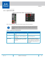
Figure 25: System Status LEDs - Front and Rear sides . . . . . . . . . . . . . . . . . . . . . . . . . . . . . . . . . . . . . 45
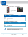
Figure 26: Fan Status LED - Front and Rear Sides . . . . . . . . . . . . . . . . . . . . . . . . . . . . . . . . . . . . . . . . . 46
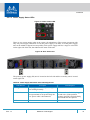
Figure 27: Power Status LED . . . . . . . . . . . . . . . . . . . . . . . . . . . . . . . . . . . . . . . . . . . . . . . . . . . . . . . . . . 47
Figure 28: Rear Side Panel . . . . . . . . . . . . . . . . . . . . . . . . . . . . . . . . . . . . . . . . . . . . . . . . . . . . . . . . . . . 47
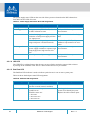
Figure 29: Port LEDs . . . . . . . . . . . . . . . . . . . . . . . . . . . . . . . . . . . . . . . . . . . . . . . . . . . . . . . . . . . . . . . . 49
Figure 30: Pull-out Tab . . . . . . . . . . . . . . . . . . . . . . . . . . . . . . . . . . . . . . . . . . . . . . . . . . . . . . . . . . . . . . 50
Figure 31: QSFP Connector Male and Female Views . . . . . . . . . . . . . . . . . . . . . . . . . . . . . . . . . . . . . . 58
Figure 32: RJ45 to DB9 Harness Pinout . . . . . . . . . . . . . . . . . . . . . . . . . . . . . . . . . . . . . . . . . . . . . . . . . 59

Rev. 1.76 Mellanox Technologies
List of Tables
Table 1: Revision History Table . . . . . . . . . . . . . . . . . . . . . . . . . . . . . . . . . . . . . . . . . . . . . . . . . 7
Table 2: References . . . . . . . . . . . . . . . . . . . . . . . . . . . . . . . . . . . . . . . . . . . . . . . . . . . . . . . . . . 8
Table 3: Speed and Switching Capabilities . . . . . . . . . . . . . . . . . . . . . . . . . . . . . . . . . . . . . . . 11
Table 4: Management Interfaces and FRUs . . . . . . . . . . . . . . . . . . . . . . . . . . . . . . . . . . . . . . 11
Table 5: Ordering Part Numbers (OPNs) . . . . . . . . . . . . . . . . . . . . . . . . . . . . . . . . . . . . . . . . 12
Table 6: Air Flow Color Legend . . . . . . . . . . . . . . . . . . . . . . . . . . . . . . . . . . . . . . . . . . . . . . . . 15
Table 7: Installation Kit . . . . . . . . . . . . . . . . . . . . . . . . . . . . . . . . . . . . . . . . . . . . . . . . . . . . . . 18
Table 8: Installation Kit . . . . . . . . . . . . . . . . . . . . . . . . . . . . . . . . . . . . . . . . . . . . . . . . . . . . . . 23
Table 9: Serial Terminal Program Configuration . . . . . . . . . . . . . . . . . . . . . . . . . . . . . . . . . . 32
Table 10: Configuration Wizard Session . . . . . . . . . . . . . . . . . . . . . . . . . . . . . . . . . . . . . . . . . . 33
Table 11: Configuration Wizard Session - Static IP Configuration . . . . . . . . . . . . . . . . . . . . . 34
Table 12: LEDs Symbols . . . . . . . . . . . . . . . . . . . . . . . . . . . . . . . . . . . . . . . . . . . . . . . . . . . . . . . 44
Table 13: System Status LED Assignments . . . . . . . . . . . . . . . . . . . . . . . . . . . . . . . . . . . . . . . . 45
Table 14: Fan Status Front LED Assignments . . . . . . . . . . . . . . . . . . . . . . . . . . . . . . . . . . . . . . 46
Table 15: Fan Status Rear LED Assignments (One LED per Fan) . . . . . . . . . . . . . . . . . . . . . . . 46
Table 16: Power Supply Unit Status Front LED Assignments . . . . . . . . . . . . . . . . . . . . . . . . . 47
Table 17: Power Supply Unit Status Rear LED Assignments . . . . . . . . . . . . . . . . . . . . . . . . . .48
Table 18: Bad Port LED Assignments . . . . . . . . . . . . . . . . . . . . . . . . . . . . . . . . . . . . . . . . . . . . 48
Table 19: Port LEDs in InfiniBand System Mode . . . . . . . . . . . . . . . . . . . . . . . . . . . . . . . . . . . 49
Table 20: Troubleshooting. . . . . . . . . . . . . . . . . . . . . . . . . . . . . . . . . . . . . . . . . . . . . . . . . . . . . 51
Table 21: SB77X0/SB78X0 Specifications . . . . . . . . . . . . . . . . . . . . . . . . . . . . . . . . . . . . . . . . . 53
Table 22: OPNs for Replacement Parts. . . . . . . . . . . . . . . . . . . . . . . . . . . . . . . . . . . . . . . . . . . 54
Table 23: QSFP Interface Pins 1-23 . . . . . . . . . . . . . . . . . . . . . . . . . . . . . . . . . . . . . . . . . . . . . . 56
Table 24: QSFP Interface Pins 24-38 . . . . . . . . . . . . . . . . . . . . . . . . . . . . . . . . . . . . . . . . . . . . . 57
Table 25: RJ-45 CONSOLE and I²C Pinout . . . . . . . . . . . . . . . . . . . . . . . . . . . . . . . . . . . . . . . . . 58

Rev. 1.7 7Mellanox Technologies
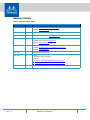
Revision History
Table 1 - Revision History Table
Date Revision Description
February 2017 1.7 Updated “RJ45 to DB9 Harness Pinout”
Updated “Specifications”
December 2016 1.6 Updated document title
September 2016 1.5 Added “Noise Level” to “Specifications”
July 2016 1.4 Added the SB7780 InfinBand router
Updated LED colors in “Interfaces”
Updated “Specifications”
March 2016 1.3 Added SB7800 and SB7890
Updated “System Bring-Up of Managed Systems”
Updated “Specifications”
July 2015 1.2 Changed document’s title
June 2015 1.1 Added:
• Hebrew safety warnings
Updated:
• Figure 1,“SB77X0/SB78X0 Front Side View”
• Table 21, “SB77X0/SB78X0 Specifications”
April 2015 1.0 Initial release

Rev. 1.78 Mellanox Technologies
About this Manual
This manual describes the installation and basic use of the Mellanox InfiniBand EDR 1U
switches.
Intended Audience
This manual is intended for IT managers and system administrators.
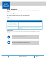
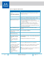
References
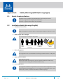
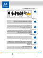
Conventions
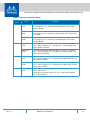
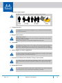
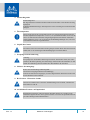
The following icons are used throughout this document to indicate information that is important
to the user.
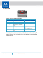
Table 2 - References
Document Description
InfiniBand Architecture Spec-
ification, Volume 1, Release
1.2.1, and Volume 2, Release
1.3
The InfiniBand Architecture Specification that is provided by IBTA
MLNX-OS® User Manual This document contains information regarding configuring and
managing MLNX-OS software- see http://www.mellanox.com/
page/mlnx_os.
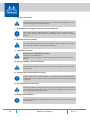
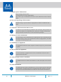
This icon makes recommendations to the user.
This icon indicates information that is helpful to the user.

Rev. 1.7 9Mellanox Technologies
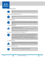
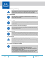
This icon indicates a situation that can potentially cause damage to hardware or
software.
This icon indicates a situation that can potentially cause personal injury.
This icon indicates a situation that can potentially cause personal injury.

Rev. 1.710 Mellanox Technologies
1 Introduction to Mellanox SB77X0/SB78X0 Switch Systems and
SB7780 InfinBand Router
1.1 Overview
The SB77X0/SB78X0 switch systems provide the highest performing fabric solution in a 1U
form factor by delivering up to 7Tb/s of non-blocking bandwidth with sub 100ns port-to-port
latency. These systems are the industry's most cost-effective building blocks for embedded sys
-
tems and storage with a need for low port density systems. Whether looking at price-to-perfor-
mance or energy-to-performance, these systems offer superior performance, power and space,
reducing capital and operating expenses and providing the best return-on-investment.
Powerful servers combined with high-performance storage and applications that use increasingly
complex computations are causing data bandwidth requirements to spiral upward. As servers are
deployed with next generation processors, High-Performance Computing (HPC) environments
and Enterprise Data Centers (EDC) need every last bit of bandwidth delivered with Mellanox's
EDR InfiniBand systems.
Built with Mellanox's latest SwitchIB™ InfiniBand EDR 100Gb/s switch device, these stand-
alone systems are an ideal choice for top-of-rack leaf connectivity or for building small to
extremely large sized clusters. These systems enable efficient computing with features such as
static routing, adaptive routing, and advanced congestion management. These features ensure the
maximum effective fabric bandwidth by eliminating congestion.
The SB7700/SB7800, dual-core x86 CPU, comes with an onboard subnet manager, enabling
simple, out-of-the-box fabric bring-up for up to 2048 nodes.
SB7700/SB7800 switch runs the same MLNX-OS® software package as Mellanox FDR prod-
ucts to deliver complete chassis management of the firmware, power supplies, fans and ports.
Mellanox's edge systems can also be coupled with Mellanox's Unified Fabric Manager (UFM®)
software for managing scale-out InfiniBand computing environments. UFM enables data center
operators to efficiently provision, monitor and operate the modern data center fabric. UFM
boosts application performance and ensures that the fabric is up and running at all times.
InfiniBand systems come as internally or externally managed. Internally managed systems
include a CPU that runs the management software (MLNX-OS®) and management ports, which
are used to transfer management traffic into the system. Externally managed systems come with
-
out the CPU and management ports, and are managed using firmware tools.
The SB7780 InfiniBand router is based on the SwitchIB™ switch ASIC, and offers fully flexible
36 EDR 100Gb/s ports, which can be split among six different subnets. The InfinBand router
brings two major enhancements to the Mellanox switch portfolio:
1. Increases resiliency by segregating the data center’s network into several subnets, with each
subnet running its own subnet manager, effectively isolating each subnet from the others’
availability or instability
2. Enables scaling of the fabric up to a virtually unlimited number of nodes.

Introduction to Mellanox SB77X0/SB78X0 Switch Systems and SB7780 InfinBand Router
Rev. 1.7
11Mellanox Technologies
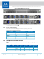
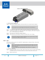
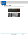
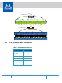
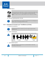
Figure 1: SB77X0/SB78X0 Front Side View
Figure 2: SB7700/SB7780/SB7800* Rear Side View
Figure 3: SB7790/SB7890 Rear Side View
*The SB7800 models include one MGT port labeled .
1.2 Speed and Switching
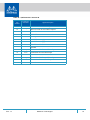
Table 3 describes maximum throughput and interface speed per system model.
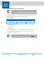
1.3 Management Interfaces and FRUs
Table 4 lists the various management interfaces and available replacement parts per system
model.
Table 3 - Speed and Switching Capabilities
System Model EDR 100Gb/s QSFP28 Interfaces Max Throughput
SB7700 36 7.2Tb/s
SB7790 36 7.2Tb/s
SB7800 36 7.2Tb/s
SB7890 36 7.2Tb/s
SB7780 36 7.2Tb/s
Table 4 - Management Interfaces and FRUs
System
Model
USB MGT I²C* Console*
Replaceable
PSU
Replaceable
Fan
SB7700 Rear Rear (2
ports)
Rear Rear Yes Yes
SB7790 NA NA Rear NA Yes Yes

Rev. 1.712 Mellanox Technologies
*The same connector is used for the I²C and the console interfaces.
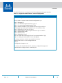
1.4 Features
For a full feature list, please refer to the systems’ product briefs:
http://www.mellanox.com/related-docs/prod_ib_switch_systems/pb_sb7700.pdf
http://www.mellanox.com/related-docs/prod_ib_switch_systems/pb_sb7790.pdf
http://www.mellanox.com/related-docs/prod_ib_switch_systems/pb_sb7800.pdf
http://www.mellanox.com/related-docs/prod_ib_switch_systems/pb_sb7890.pdf
http://www.mellanox.com/related-docs/prod_ib_switch_systems/pb_sb7780.pdf
1.5 Certifications
The list of certifications (such as EMC, Safety and others) per system for different regions of the
world is located on the Mellanox website at:
http://www.mellanox.com/page/environmental_compliance
1.6 Ordering Information
the following table lists ordering information for the available systems. Please pay attention to
the airflow direction when ordering your system. For more details, see
“Air Flow” on page 15.
SB7800 Rear Rear (1
port)
Rear Rear Yes Yes
SB7890 NA NA Rear NA Yes Yes
SB7780 Rear Rear (2
ports)
Rear Rear Yes Yes
Table 5 - Ordering Part Numbers (OPNs)
System
Model
OPN Description
SB7700 MSB7700-
ES2F
Switch-IB™ based EDR InfiniBand 1U Switch, 36 QSFP28 ports, 2
Power Supplies (AC), x86 dual core, standard depth, P2C airflow,
Rail Kit, RoHS6
MSB7700-
ES2R
Switch-IB™ based EDR InfiniBand 1U Switch, 36 QSFP28 ports, 2
Power Supplies (AC), x86 dual core, standard depth, C2P airflow,
Rail Kit, RoHS6
MSB7700-
EB2F
Switch-IB™ based EDR InfiniBand 1U Switch, 36 QSFP28 ports, 2
Power Supplies (AC), x86 dual core, short depth, P2C airflow, Rail
Kit, RoHS6
Table 4 - Management Interfaces and FRUs
System
Model
USB MGT I²C* Console*
Replaceable
PSU
Replaceable
Fan

Introduction to Mellanox SB77X0/SB78X0 Switch Systems and SB7780 InfinBand Router
Rev. 1.7
13Mellanox Technologies
SB7790 MSB7790-
ES2F
Switch-IB™ based EDR InfiniBand 1U Switch, 36 QSFP28 ports, 2
Power Supplies (AC), unmanaged, standard depth, P2C airflow,
Rail Kit, RoHS6
MSB7790-
EB2F
Switch-IB™ based EDR InfiniBand 1U Switch, 36 QSFP28 ports, 2
Power Supplies (AC), unmanaged, Short depth, P2C airflow, Rail
Kit, RoHS6
MSB7790-
ES2R
Switch-IB™ based EDR InfiniBand 1U Switch, 36 QSFP28 ports, 2
Power Supplies (AC), unmanaged, standard depth, C2P airflow,
Rail Kit, RoHS6
SB7800 MSB7800-
ES2F
Switch-IB(TM)-2 based EDR InfiniBand 1U Switch, 36 QSFP28
ports, 2 Power Supplies (AC), x86 dual core, standard depth, P2C
airflow, Rail Kit, RoHS6
MSB7800-
ES2R
Switch-IB(TM)2 based EDR InfiniBand 1U Switch, 36 QSFP28
ports, 2 Power Supplies (AC), x86 dual core, standard depth, C2P
airflow, Rail Kit, RoHS6
SB7890 MSB7890-
ES2F
Switch-IB(TM)-2 based EDR InfiniBand 1U Switch, 36 QSFP28
ports, 2 Power Supplies (AC), unmanaged, standard depth, P2C air
-
flow, Rail Kit, RoHS6
MSB7890-
ES2R
Switch-IB(TM)2 based EDR InfiniBand 1U Switch, 36 QSFP28
ports, 2 Power Supplies (AC), unmanaged, standard depth, C2P air
-
flow, Rail Kit, RoHS6
SB7780 MSB7780-
ES2F
SwitchIB™-based 36-port QSFP28 EDR 1U Managed InfiniBand
router system with a
non-blocking switching capacity of 7Tb/s. 2PS, Standard depth,
P2C airflow, RoHS-6
Table 5 - Ordering Part Numbers (OPNs)
System
Model
OPN Description

Installation
Rev. 1.7
14Mellanox Technologies
2 Installation
Installation and initialization of the system require attention to the normal mechanical, power,
and thermal precautions for rack-mounted equipment.
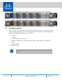
The installation procedure for the system involves the following phases:
Step 1. Follow the safety warnings in Section 2.1 on page 14
Step 2. Pay attention to the air flow consideration within the system and rack - refer to “Air Flow”
on page 15
Step 3. Make sure that none of the package contents is missing or damaged - see “Package Con-
tents” on page 17
Step 4. Mount the system as suggested in “Mounting Options” on page 18
Step 5. Power on the system - refer to “Initial Power On” on page 30
Step 6. Perform system bring-up - see “System Bring-Up of Managed Systems” on page 31
FRU replacements are described in Section 2.8 on page 36.
2.1 Safety Warnings
Prior to the installation, please review the safety warnings as follows:
• For Nordic Countries Notices, see Section E.1, “Nordic Countries Notices,” on page 61.
• For Safety Warnings in English, see Section E.2, “Installation Safety Warnings
(English),” on page 61.
• For Safety Warnings in Hebrew, see Section E.3, “תירבע) הנקתהב תוחיטב תורהזא),” on
page 64.
• For Safety Warnings in Chinese, see Section E.4 on page 68.
• For Safety Warnings in French, see Section E.5, “Avertissements de sécurité pour
l'installation (French),” on page 72.
• For Safety Warnings in German, Section E.6, “Installation Sicherheitshinweise(Ger-
man),” on page 76.
• For Safety Warnings in Spanish, see Section E.7, “Advertencias de seguridad de insta-
lación (Spanish),” on page 79.
• For Safety Warnings in Russian, see Section E.8, “Предупреждения по технике
безопасности при установке (Russian),” on page 83.
• For Safety Warnings in Romanian, see Section E.9, “Avertismente privind siguranţa la
instalare (Romanian),” on page 87.
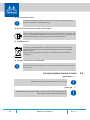
The rack mounting holes conform to the EIA-310 standard for 19-inch racks. Take
precautions to guarantee proper ventilation in order to maintain good airflow at ambi
-
ent temperature.

Rev. 1.715 Mellanox Technologies
• For Safety Warnings in Croatian, see Section E.10, “Sigurnosna upozorenja za instali-
ranje (Croatian),” on page 90.
• For Safety Warnings in Italian, see Section E.11, “Avvertenze di sicurezza per
l’installazione (Italian),” on page 94.
• For Safety Warnings in Turkish see Section E.12, “Montaj Güvenlik Uyarıları (Turk-
ish),” on page 98.
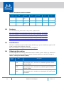
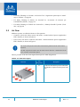
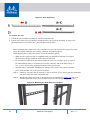
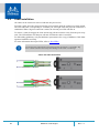
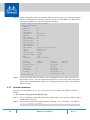
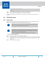
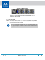
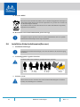
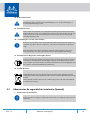
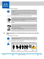
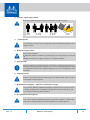
2.2 Air Flow
Mellanox systems are offered with two air flow patterns:
• Connector (front) side inlet to power side outlet - marked with red power supplies/fans
FRUs’ handles, as shown in
Figure 4.
• Power (rear) side inlet to connector side outlet - marked with blue power supplies/fans
FRUs’ handles, as shown in
Figure 5.
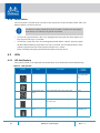
Table 6 provides an air flow color legend and respective OPN designations.
All servers and systems in the same rack should be planned with the same airflow
direction.
All FRU components need to have the same air flow direction. A mismatch in the air
flow will affect the heat dissipation.
Table 6 - Air Flow Color Legend
Direction
OPN
Designation
Description
R
Connector side inlet to power side outlet.
Red latches are placed on the power inlet
side.

Installation
Rev. 1.7
16Mellanox Technologies
F
Power side inlet to connector side outlet.
Blue latches are placed on the power
inlet side.
Table 6 - Air Flow Color Legend
Direction
OPN
Designation
Description

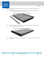
Rev. 1.717 Mellanox Technologies
Figure 4: Air Flow Direction Marking - Power Side Inlet to Connector Side Outlet
Figure 5: Air Flow Direction Marking - Connector Side Inlet to Power Side Outlet
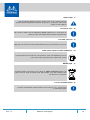
2.3 Package Contents
Before installing your new system, unpack it and check against the parts list below that all the
parts have been sent. Check the parts for visible damage that may have occurred during shipping.
The SB77X0/SB78X0 package content is as follows:
• 1 x System
• 1 x Rail kit
• 2 x Power cables – Type C13-C14
• 1 x Harness: HAR000028 – Harness RS232 2M cable – DB9 to RJ-45 (in SB7X00 mod-
els only)
• 2 x Cable retainers
•Quick Start Guide
If anything is damaged or missing, contact your sales representative at support@mella-
nox.com.

Installation
Rev. 1.7
18Mellanox Technologies
2.4 Mounting Options
By default, the system is sold with the Static Rail-kit described in Section 2.4.1. A Telescopic
rail-kit can be purchased separately. For the Telescopic Rail-kit installation instructions, see Sec-
tion 2.4.2.
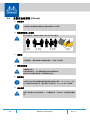
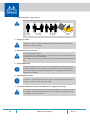
2.4.1 19” Systems Mounting - Static Rail-Kit
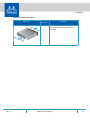
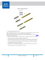
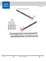
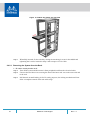
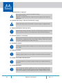
The following parts are included in the Static Rail kit (see Figure 6):
• 2x Rack mount rails (A)
• 2x Rack mount brackets (B)
• 2x Rack mount blades (C)
• 8x M6 Standard cage nuts and 8x M6 Standard pan-head Phillips screws (D)
• 4x Phillips100 DEG F.H TYPE-I ST.ST 6-32 X 1/4 screw with around patch (E)
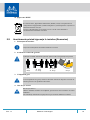
At least two people are required to safely mount the system in the rack.
Table 7 - Installation Kit
Kit OPN Rack Size and Rack Depth Range
MTEF-KIT-A Short (17”-24”) or Standard (24”-34”)

Rev. 1.719 Mellanox Technologies
Figure 6: Rack Rail Kit Parts
To mount the system into the rack:
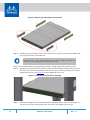
Before mounting the system to the rack, select the way you wish to place the system. Pay atten-
tion to the airflow within the rack cooling, connector and cabling options.
While planning how to place the system, consider the two installation options shown in Figure 7,
and review the following points:
• Make sure the system air flow is compatible with your installation selection. It is import-
ant to keep the airflow within the rack in the same direction.
• Note that the part of the system to which you choose to attach the rails (the front panel
direction, as demonstrated in Option 1 or the FRUs direction, as demonstrated in Option
2) will determine the system’s adjustable side. The system’s part to which the brackets
are attached will be adjacent to the cabinet.
• The FRU side is extractable. Mounting the rack brackets inverted to the FRU side
(Option 2) will allow you to slide the FRUs, in and out.

Installation
Rev. 1.7
20Mellanox Technologies
Figure 7: Installation Options
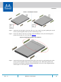
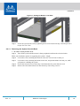
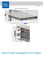
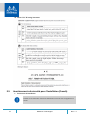
Step 1. Attach the left and right rack mount rails (A) to the switch, by gently pushing the switch
chassis’ pins through the slider key holes, until locking occurs.
Step 2. Secure the chassis in the rails, screwing 2 flat head Phillips screws (E) in the designated
points with a torque of 1.5±0.2 Nm. See
Figure 8.
Figure 8: Attaching the Rails to the Chassis
Step 3. Attach the left and right rack mount brackets (B) to the switch, by gently pushing the switch
chassis’ pins through the slider key holes, until locking occurs. Secure the system in the
brackets by screwing the remaining 2 flat head Phillips screws (E) in the designated points
with a torque of 1.5±0.2 Nm. See
Figure 9.
La pagina sta caricando ...
La pagina sta caricando ...
La pagina sta caricando ...
La pagina sta caricando ...
La pagina sta caricando ...
La pagina sta caricando ...
La pagina sta caricando ...
La pagina sta caricando ...
La pagina sta caricando ...
La pagina sta caricando ...
La pagina sta caricando ...
La pagina sta caricando ...
La pagina sta caricando ...
La pagina sta caricando ...
La pagina sta caricando ...
La pagina sta caricando ...
La pagina sta caricando ...
La pagina sta caricando ...
La pagina sta caricando ...
La pagina sta caricando ...
La pagina sta caricando ...
La pagina sta caricando ...
La pagina sta caricando ...
La pagina sta caricando ...
La pagina sta caricando ...
La pagina sta caricando ...
La pagina sta caricando ...
La pagina sta caricando ...
La pagina sta caricando ...
La pagina sta caricando ...
La pagina sta caricando ...
La pagina sta caricando ...
La pagina sta caricando ...
La pagina sta caricando ...
La pagina sta caricando ...
La pagina sta caricando ...
La pagina sta caricando ...
La pagina sta caricando ...
La pagina sta caricando ...
La pagina sta caricando ...
La pagina sta caricando ...
La pagina sta caricando ...
La pagina sta caricando ...
La pagina sta caricando ...
La pagina sta caricando ...
La pagina sta caricando ...
La pagina sta caricando ...
La pagina sta caricando ...
La pagina sta caricando ...
La pagina sta caricando ...
La pagina sta caricando ...
La pagina sta caricando ...
La pagina sta caricando ...
La pagina sta caricando ...
La pagina sta caricando ...
La pagina sta caricando ...
La pagina sta caricando ...
La pagina sta caricando ...
La pagina sta caricando ...
La pagina sta caricando ...
La pagina sta caricando ...
La pagina sta caricando ...
La pagina sta caricando ...
La pagina sta caricando ...
La pagina sta caricando ...
La pagina sta caricando ...
La pagina sta caricando ...
La pagina sta caricando ...
La pagina sta caricando ...
La pagina sta caricando ...
La pagina sta caricando ...
La pagina sta caricando ...
La pagina sta caricando ...
La pagina sta caricando ...
La pagina sta caricando ...
La pagina sta caricando ...
La pagina sta caricando ...
La pagina sta caricando ...
La pagina sta caricando ...
La pagina sta caricando ...
La pagina sta caricando ...
-
 1
1
-
 2
2
-
 3
3
-
 4
4
-
 5
5
-
 6
6
-
 7
7
-
 8
8
-
 9
9
-
 10
10
-
 11
11
-
 12
12
-
 13
13
-
 14
14
-
 15
15
-
 16
16
-
 17
17
-
 18
18
-
 19
19
-
 20
20
-
 21
21
-
 22
22
-
 23
23
-
 24
24
-
 25
25
-
 26
26
-
 27
27
-
 28
28
-
 29
29
-
 30
30
-
 31
31
-
 32
32
-
 33
33
-
 34
34
-
 35
35
-
 36
36
-
 37
37
-
 38
38
-
 39
39
-
 40
40
-
 41
41
-
 42
42
-
 43
43
-
 44
44
-
 45
45
-
 46
46
-
 47
47
-
 48
48
-
 49
49
-
 50
50
-
 51
51
-
 52
52
-
 53
53
-
 54
54
-
 55
55
-
 56
56
-
 57
57
-
 58
58
-
 59
59
-
 60
60
-
 61
61
-
 62
62
-
 63
63
-
 64
64
-
 65
65
-
 66
66
-
 67
67
-
 68
68
-
 69
69
-
 70
70
-
 71
71
-
 72
72
-
 73
73
-
 74
74
-
 75
75
-
 76
76
-
 77
77
-
 78
78
-
 79
79
-
 80
80
-
 81
81
-
 82
82
-
 83
83
-
 84
84
-
 85
85
-
 86
86
-
 87
87
-
 88
88
-
 89
89
-
 90
90
-
 91
91
-
 92
92
-
 93
93
-
 94
94
-
 95
95
-
 96
96
-
 97
97
-
 98
98
-
 99
99
-
 100
100
-
 101
101


Mellanox Technologies SB7800 Manuale utente
- Tipo
- Manuale utente
in altre lingue
Documenti correlati
-
Mellanox Technologies SX6730 Hardware User Manual
-
-
Mellanox Technologies SX6005 Manuale utente
-
-
-
-
Altri documenti
-
Paulmann 788.80 V Strips 55 Zoll 78880 LED Strip Basic Set Istruzioni per l'uso
-
Tyan Transport GT26-B4987 Manuale utente
-
-
Tyan Thunder S4987 Manuale utente
-
D-Link DSR-250 Manuale del proprietario
-
Allied Telesis AT-PWR01 Guida d'installazione
-
-
Fracarro SIG7900 Istruzioni per l'uso