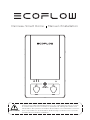
EcoFlow Smart Home Panel Combo(13 relay modules) Manuale utente
- Tipo
- Manuale utente

Smart Home Panel Installation Manual
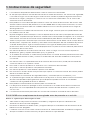
WARNING
The EcoFlow Smart Home Panel must be installed by a licensed electrician,
who should be familiar with all electrical codes, electrical wiring practices and
experience working with home electrical systems. Any accident, damage or
personal injury caused by incorrect installation is the sole responsibility of the
user.


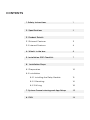
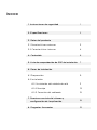
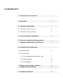
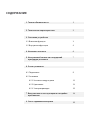
CONTENTS
3. Product Details
2. Specifications
4. What's in the box
5. Installation SOP Checklist
1. Safety Instructions
3.1 External Features
3.2 Internal Features
3
4
1
2
6. Installation Steps
7. System Commissioning and App Setup
8. FAQ
6.1 Preparation
6.2 Installation
6.2.1 Installing the Relay Module
6.2.2 Mounting
6.2.3 Wiring
10
12
14
16
23
24
6
7

1
3
4
1
2
6.1 Preparation
6.2 Installation
6.2.1 Installing the Relay Module
6.2.2 Mounting
6.2.3 Wiring
10
12
14
16
23
24
6
7
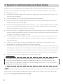
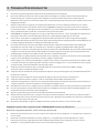
1. Open all connected upstream circuit breakers and make sure the Grid Power Indicators are off.
2. Turn off DELTA Pro(s) from the SHP and ensure the DELTA Pro Power Indicators are off.
3. The alarm will sound if the SHP is energized while the front cover is open. Please ensure that the
unit is de-energized and the alarm has stopped
The SHP MUST be completely de-energized before being serviced
Complete the following to de-energize the SHP
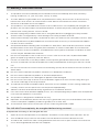
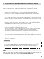
1. The product must be installed by a licensed electrician and verified by local AHJ (Authority
Having Jurisdiction, i.e., your city, town, county or state).
2. The SHP defaults to grid mode when not powered. For safety, do not access or disconnect any
load circuits when there is an internal fault. Power down those loads and contact a licensed
electrician or EcoFlow technical support.
3. This product is not intended to be used as a service disconnect. To completely de-energize the
product, the user MUST open the upstream breakers as well as physically unplug all DELTA Pros.
Failure to do so may present a shock hazard.
4. DO NOT unplug relay modules while SHP is energized, because unplugging the relay module
while the SHP is energized may cause damage to the relay modules and SHP.
5. Smart Home Panel by itself does not provide an AFCI (Arc Fault Circuit Interrupter) function. AFCI
or GFCI protection may be available with an external AFCI accessory. Consult EcoFlow support
for AFCI or GFCI solutions.
6. All upstream breakers feeding SHP should be non-GFCI/AFCI. GFCI and AFCI protection should
be downstream of the SHP using GFCI/AFCI breakers or outlets. Follow NEC or local electrical
codes for AFCI or GFCI installation. An additional accessory panel to aid with installation of AFCI
circuits may be available from EcoFlow.
7. Do not use the product near a heat source, such as a fire or furnace. Do not place flammable
gases or liquids (e.g. Gasoline) near the device.
8. If there is a loud noise in the relay module, there may be a ground fault downstream of the SHP.
The user should clear the fault and replace the relay module before resetting the SHP for normal
use.
9. Do not use the SHP if the Short-Circuit Current Rating (SCCR) at the electrical service entrance is
above 10kA.
10. Do not install or operate the product outdoors or in damp/wet conditions.
11. Do not install or operate the product in extreme temperatures.
12. Do not use the product if it is damaged or appears to be damaged.
13. Do not connect the relay channels to circuit breakers higher than their current rating. Doing so
can result in damage to the relay modules.
14. The split-phase mode should be used for multi-wire circuits (MWBC, circuits sharing a balanced
neutral), and the circuits split across the two phases appropriately.
15. Adhere to all local and national safety regulations for installation and use.
16. If an overcurrent fault (breaker tripped) occurs, the corresponding relay module must be replaced
to ensure safe operation in the future.
17. This product is designed for residential use only.
18. Upstream circuit breakers protect the SHP only in grid mode. Only use circuit breakers with a fault
current interruption capability of 10kA or greater, 4ms or 5kA, 8ms.
19. The maximum total current for all input circuits under the grid mode is 160A.
1. Safety Instructions

2
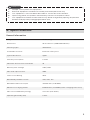
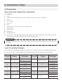
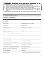
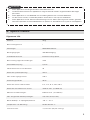
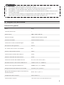
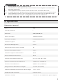
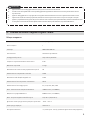
2. Specifications
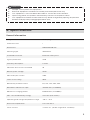
General Information
Weight
Dimensions
Mounting Type
Standard Connector
Type of Enclosure
Warranty Description
Maximum # of Circuits Controlled
Rated System Voltage
Max Total Input Current
Short Circuit Rating
Rated Relay Module Current
Rated Max DELTA Pro Input
DELTA Pro Charging Power
Max Connected Battery Energy
Operating Humidity (RH)
20 lbs (9 kg)
19.7x11.8x4.7 in (500x330x120 mm)
Wall Mount
EcoFlow Infinity Port
Type 1
5 Years
10
120V/240V
160A
10kA
30A, 20A, 15A
7200W Max (2x3600W)
6800W Max (2x3400W)(Max. charging time <3hrs)
21.6 kWh (6x3.6kWh)
5-85%
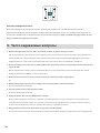
1. Multiple sources power this equipment.
2. Electrical equipment should be serviced by authorized personnel only.
3. This equipment is not intended to be used as a service disconnect breaker.
4. Upon losing power, this product automatically switches to the power station.
5. This equipment and downstream load can only be de-energized by opening all upstream
breakers and physically unplugging all DELTA Pros.
DANGER

3
1
2
3
4
5
6
7
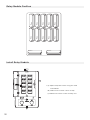
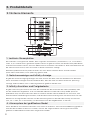
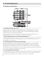
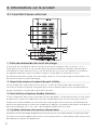
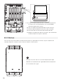
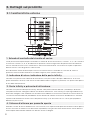
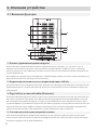
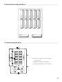
The SHP can be set up to control a total of 10 load circuits, circuits 1, 3, 5, 7, 9 on the left and 2, 4, 6, 8,
10 on the right. There is a button allowing users to manually reset each circuit relay if there has been
an overcurrent event on the circuit. An indicator lamp on the button turns red if there is a fault in that
circuit.
A lightning bolt indicator for each load circuit is illuminated if that load circuit is energized through one
of the sources (grid or power station).
There are three energization indicators on the SHP, one for the grid, two for the DELTA Pros. If any of
these indicators are illuminated, SHP is energized from that source and, therefore, cannot be opened to
be serviced.
There are two infinity ports on the SHP, which can be either on the bottom of the SHP (default),
or relocated to the front. They connect DELTA Pros to the SHP through the Infinity Cable (one for
each DELTA Pro). Once plugged in, SHP and DELTA Pro will try to establish connection through
communication and SHP’s control circuitry may be powered via DC current from the DELTA pro. Press
the enable button located near the infinity port (labeled “AC 1” or “AC2” to make DELTA Pro ready for
output.
When the DELTA Pro load circuits are energized, an alarm will sound if the front panel cover is opened.
To de-energize the product, all upstream breakers must be opened and both DELTA Pros must be
unplugged.
1. Load Circuit Control Board
3.1 External Features
2. Grid Indicator and Infinity Port Indicator
3. Infinity Port and Enable Button
4. Panel Open Alarm System
3. Product Details

4
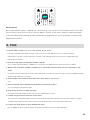
This button can be used to turn on the Bluetooth hotspot for 5 minutes for the user to connect.
This indicator is normally off if no fault is present inside the SHP. It will turn red if there is a fault in
the product. Users can go to the app for a fault diagnostic report. If there is an issue, please contact
customer support for assistance.
5. IOT Reset Button and Indicator
6. Error Indicator
The pause button will physically isolate the 10 load circuits and lock out both connected DELTA Pros.
A signal from the SHP will tell the DELTA Pros to stop outputting power. Please note that this does not
substitute for a service disconnect, nor does it substitute for the de-energization procedure required
before servicing.
This is the only “quick disconnect” that can be used to manually cut all power in an emergency.
AC in and Pro in still energize.
7. Power Station Pause/Resume Button
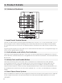
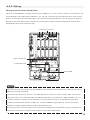
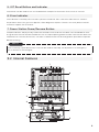
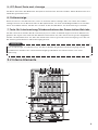
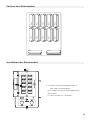
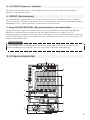
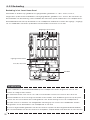
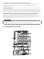
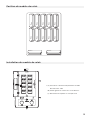
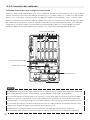
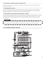
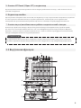
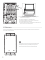
3.2 Internal Features
1
2
3
4
5
6
7
8
9
NOTE

5
1. Output Wire Connectors
2. Communication Ports connecting to the key panel
3. Relay Modules
These are the wire connectors for output hot wires going to the load.
The relay modules are available in different current ratings, 15A, 20A and 30A. These modules contain
two relays for each circuit as well as an overcurrent protection fuse. Each module can be individually
replaced without affecting other circuits. De-energize the SHP before replacing any module.
4. DELTA Pro Wire Connectors
5. Infinity Ports
6. Cooling Fan
7. Ground Bus Bar
8. Input Wire Connectors
9. Switching Connector for Single/Split Phase Operation
These are wire connectors for DELTA Pro. There is one hot wire and one neutral wire required for each
DELTA Pro. At least one neutral wire must be connected to the main panel even if no DELTA Pro is
used. This neutral is used as a return path for DELTA Pro to power your circuits.
Infinity ports can be installed either on the front or the bottom of the product. Users can choose to
switch the position of the Infinity ports. This can improve cable management in tight quarters.
The cooling fan is activated under extreme operating conditions to reduce the ambient temperature
inside of the unit.
This is the ground bus bar, which should be connected to the ground bus bar in the main electrical
panel. The panel casing is connected to this ground. NOTE: Please follow NEC and/or local code
requirements with regard to bonding neutral and ground. Bonding should be done at the first means of
disconnect, which is the service panel, NOT the SHP.
These are the wire connectors for hot wires coming from the circuit breakers in your main panel.
For split phase operation (North America and Japan ONLY), this connector should be removed
permanently from the product. Split-phase also requires additional setup in the EcoFlow app.

6
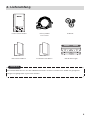
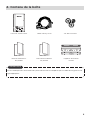
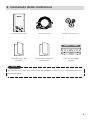
4. What’s in the Box
Smart Home Panel
Product User Manual Product Installation
Manual
Wall mounting brackets
A bag of accessoriesInfinity Cable and
Wires
The AWM wires can be removed from the harness plugs and replaced with an appropriate length
and type of cable.
NOTE

7
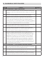
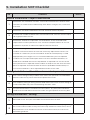
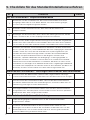
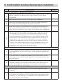
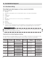
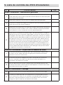
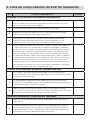
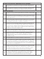
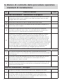
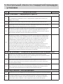
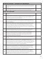
5. Installation SOP Checklist
No. Checklist Status
Before installation- Project information
1
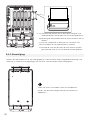
Determine the installation location. The Smart Home Panel is rated to IP20,
therefore, it needs to be installed away from direct sunlight, rain, snow and
moisture.
2Determine the distance between the SHP and main electrical panel.
3
Determine if there is a split-phase or double pole load (240V/200V or
MWBC, USA and Japan only) that needs to be connected to the SHP. Channel
1, 3, 5, 7, 9 AC input should be connected on the same phase (phase a),
whereas Channel 2, 4, 6, 8, 10 AC input should be connected on the opposite
phase (phase b) when using the split-phase function. Mismatched phases will
result in an error condition and SHP will not function properly.
4Confirm the number of loads to be connected to SHP. You can connect up to
10 single pole load circuits, or up to 5 double pole load circuits.
5
Determine whether the upstream circuit breakers of the selected loads
require AFCI or GFCI protection. This can be accomplished with an on-site
inspection or photo or video of the panel from the end user.
6
Determine and gather required materials. SHP can support up to 1 1/2 “
conduit via five knockouts. Ensure that necessary adjustment factors (for
number of conductors) are accounted for and that wire ampacity is sized
appropriately. For longer runs it is recommended that you use separate
conduits for the input and output wires. USA ONLY - For AFCI and GFCI
breakers, an additional standard overcurrent trip breaker is required. For
circuits where AFCI protection is required, metal conduit or whip to the
SHP from the main panel is required to comply with NEC requirements. An
external AFCI enclosure (available from EcoFlow) to house AFCI breakers is
also required downstream of the SHP.
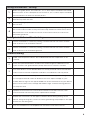
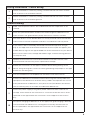
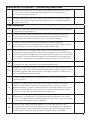
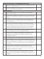
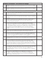
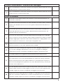
During installation - Circuit breaker and relay module
1The current rating of relay module must match the upstream circuit breaker.
Failure to do so may cause overcurrent protection to fail.
2The ampacity rating of wiring used should match the circuit current. Using an
undersized cable may cause overheating and even a fire.
3All upstream breakers should be non-GFCI/AFCI. Any AFCI/GFCI breakers
need to be moved downstream of the SHP using an optional accessory box.

8
During installation - Wiring
1
When using split phase, the Channel 1, 3, 5, 7, 9 AC input should be connected
with hot wires on the same phase, the Channel 2, 4, 6, 8, 10 AC input should be
connected with hot wires on another phase.
2For split phase operation, the Switching Connector should be removed
permanently from the SHP.
3When using single phase, each load circuit AC input should be connected to
the hot wire.
4
Install the relay modules in the corresponding places and secure by tightening
the screws. Failure to do so may cause the relay module to come loose, which
will produce an error and disconnection of the load channel, as well as risk
overheating and fire.
During installation - Check wiring
1With a multimeter in continuity setting, confirm that the hot wire in of each
SHP channel is not shorted to neutral.
2With a multimeter in continuity setting, confirm that the hot wire in of each
SHP channel is not shorted to ground.
Commissioning
1Make sure the power stations are enabled and that the stop button is off
(raised).
2Close the upstream breaker of DELTA Pro and energize the DELTA Pro AC
Input channel. The grid indicator (white) will turn on if there is no fault.
3Turn each branch circuit breaker back on one by one and check the indicator
status of each channel and power indicator. The indicators will stay white.
4
If you haven’t done so already, download the EcoFlow app from Google Play
or the App Store and create an EcoFlow account. Open the app on your
mobile device, log into the app and add the Smart Home Panel to your device
pool. For first time users, the app will lead through a commissioning process
to setup the SHP.
5Update the firmware of the Smart Home Panel to the latest version, then
check whether there are any errors reported on the app.
6
Follow the instructions in the app to conduct device wiring testing. If the
device wiring testing fails, correct the wiring following the prompts in the app
and re-run the wiring test.
7Turn on the DELTA Pro and update the firmware to the latest version.

9
No. Checklist Status
8
Connect the DELTA Pro and Smart Home Panel using the Infinity cable. For
split-phase, two DELTA Pros and two infinity cables are required. Turn on the
main power button of DELTA Pro, then press the On/Off button (AC button,
near the infinity port) on the SHP to enable each DELTA Pro.
9
Switch the power supply from grid to power station for each channel via
the app. Check whether the switchover is successful and there are no errors
reported on the app. Follow the instructions on the app to fix the errors if
any.
10
Set up the charging for DELTA Pro on the app (if AC grid charging is desired),
check whether the DELTA Pro is recharged successfully and there are no
errors reported on the app. Follow the instructions on the app to fix the
errors if any.

10
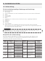
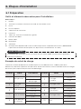
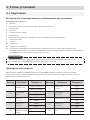
6. Installation Steps
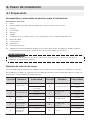
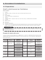
6.1 Preparation
Tools and Items Needed for Installation:
Tools required:
1. Level
2. Phillips head screwdriver, Torx T20 screwdriver and 7mm socket screwdriver
3. Pliers
4. Wire cutters
5. Wire nuts
6. Drill
7. Conduit (e.g. 1,1/4 inch and 1 inch), Conduit whip
8. Wire harness
9. Tape measure
10. Multimeter
11. Voltage detector
12. Purchase a new double pole 30A circuit breaker or two single pole 30A circuit breakers. (NOTE:
these breakers may be required to be handle tied per code.)
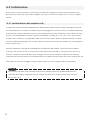
WARNINGWARNING
Installation of this product involves high voltage. Please hire a licensed electrician to perform the
installation.
Circuit
1Refrigerator 700W running
2000W startup
200W
1400W
800W
700W
0W
1000W
0W
1000W
400W
500W
300W
1200W
700W
0W
0W
0W
0W
1000W
Kitchen Light
Kitchen Plug
Bedroom Plug
Bedroom Light
Bathroom Light
Living Room Light
Living Room Light
Furnace
Sump Pump
Plug
2
3 4
5 6
7 8
910
CircuitName NameWattage Wattage
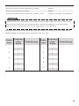
Load Calculation Example
The total DELTA Pro wattage (3600W for single Pro or 7200W for two Pros) should be greater than
the total continuous running wattage of all backed up loads plus the largest start-up wattage.

11
Total Running Load
Largest Estimated Simultaneous Running Load (LESRL)
Largest Startup Wattage (LSW)
Minimum Backup Power Needed = LESRL + LSW
6900 W
2300 W
2000 W
4300 W (Two DELTA Pros)
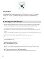
Inductive loads such as air conditioners, clothes dryers or pumps have high Inrush current when
starting. This may trip the relay modules because of overload. Ensure the circuit is sized appropriately
for the intended load.
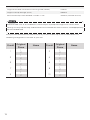
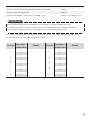
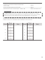
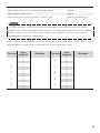
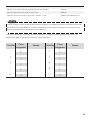
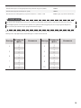
Once you have determined the load circuits that you want to back up, fill out the table below. The
numbering arrangement is the same as your SHP.
Circuit
11
1
1
2
2
2
2
3 4
5 6
7 8
910
Circuit
Original
Phase
Original
Phase
Name Name
1
1
2
2
1
1
1
2
2
2
1
1
2
2
NOTE

12
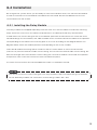
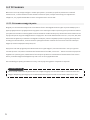
6.2 Installation
De-energize the system: When you are ready to start the installation work, turn off the main breaker
as well as each branch circuit breaker intended to be connected. Ensure that DELTA Pros are not
connected to the SHP as well.
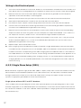
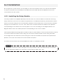
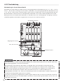
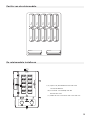
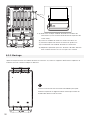
The relay modules are shipped separately from the main unit. These modules include two switching
relays and a fuse. The fuse is for load circuit protection in the backup mode only and therefore
should match the current rating for the circuit breaker upstream of that load circuit. There are three
standard ratings for the modules, 15A, 20A and 30A. Users should install these modules at the position
corresponding to the load circuits that they plan to use it for according to the diagram below. The
diagram below shows the module position corresponding to the circuit number.
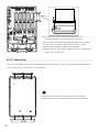
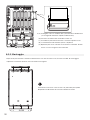
There are 10 module mounting spaces inside the SHP as shown below. 4 out of the 10 channels
(channel 1-4) have a maximum of 30A current rating, the rest have a maximum 20A current rating. No
load circuit larger than the maximum current rating for a channel should be connected. Once placed
into position, two screws are used to secure the module into place.
It's easier if the knockouts are removed before the SHP is installed on the wall.
NOTE
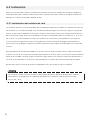
The actual continuous current rating for each relay module is 80% of module rating. For example,
for the 20A relay module, the continuous current rating is 20A × 0.8 = 16A.
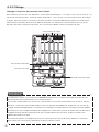
6.2.1 Installing the Relay Module

13
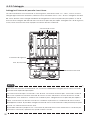
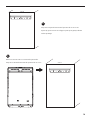
1. (a) Open the panel cover using the T20
screwdriver.
(b) Slide out the screw cover on top.
(c) Release the four screws one by one.
Relay Module Position
Install Relay Module
aa
bb
cc
01
30A MAX
02
30A MAX
03
30A MAX
04
30A MAX
05
20A MAX
06
20A MAX
07
20A MAX
08
20A MAX
09
20A MAX
10
20A MAX
DELTA Pro DELTA Pro

14
2. (a) Plug in each relay module and seat firmly (it is
recommended to use the palm of your hand).
(b) Secure the relay module by tightening the two screws.
(c) Close the front panel, and secure the four screws.
(d) The Relay Module installation is complete.
(e) Repeat for all 10 relays. 10 relays must be installed even
if they are not all used
After you have placed the relay module inside and fastened the screws, attach both top and bottom
mounting brackets to the SHP as shown below.
6.2.2 Mounting
1
Position the SHP center to center to your main panel.
Please follow the local safe electrical clearance distance.

15
2
Attach the top mounting bracket along the top edge
of the mark on the wall. Make sure you also check the
length of the flexible conduit.
wall
3
Hang the SHP up on the wall bracket.
Secure the bottom mounting bracket to the wall. wall

16
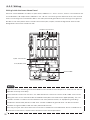
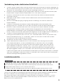
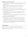
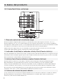
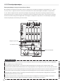
Wiring inside the Smart Home Panel
All wires come labeled in the box, 12 input wires, labeled "1 in - 10 in" "Pro1 in, Pro2 in" connected to the
circuit breakers, 10 output wires, labeled "1 out - 10 out" connecting to the load hot wires, two neutral
wires connecting to the neutral bus bar in the main panel and ground wire connecting to the ground
bus bar in the main panel. Users should connect all input, output, neutral and grounds wire to their
designated connectors inside the SHP.
6.2.3 Wiring
Pro1,N1,N2,Pro2
Ground bar
Output connectors
Input connectors
NOTE
Two neutral wires and the ground wire must be connected to the main panel in order for the SHP to
operate correctly and safely.
The maximum current for circuits 1-4 is 30A. Maximum current for circuits 5-10 is 20A. The current
rating for each circuit should not be exceeded. Please plan the load circuits appropriately. If a non-
metallic conduit is used to connect between the main panel and SHP, an equipment grounding
conductor needs to be present inside each conduit. Additional ground wires can be connected
between the ground bar inside the main panel and the SHP.
You may use your own wires with the connectors instead of the included wire. Use a screwdriver to
remove the connectors, strip the wire and then insert and torque down

17
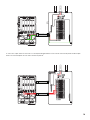
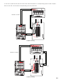
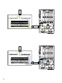
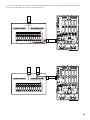
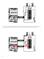
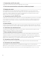
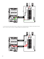
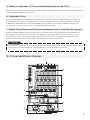
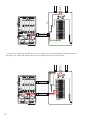
1. Run a cable from the grounding bus of the main electrical panel to the grounding bar in SHP. Install
two 30A single pole or one 30A double pole circuit breaker(s) to the main electrical panel and connect
Pro 1 and Pro 2 modules in SHP with a 10AWG cable to provide AC charging and overcurrent protection
for the Delta Pro(s).
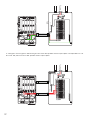
Single-phase without GFCI or AFCI breakers
Below illustrates a typical single-phase 120V (100V in Japan) setup. SHP can be connected to the main
electrical panel to provide backup power to ten 120V load circuits. All input wires should be routed
through the bottom conduit into the SHP and output wires through the upper conduit. The whole
system is single point grounded at the main electrical panel.
6.2.3.1 Single Phase Setup (120V)
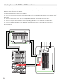
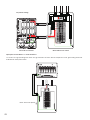
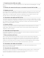
1. Turn off the main breaker as well as the 10 branch circuit breakers intended to be connected in the
main panel and use a voltage detector or voltmeter to make sure the system is fully de-energized.
2. Remove the front cover of the main panel. Keep in mind that the grid side of the main panel
(upstream of the main breaker) is still energized.
3. Remove the knockouts that you want to use on both the SHP and the main electrical panel.
4. Attach both top and bottom conduit to the SHP and main electrical panel.
5. Pull all wires (Input, output, neutral and ground) from the SHP to the main electrical panel.
6. Connect the two neutral wires and the ground wire to the neutral and ground bus respectively.
Cut them to the appropriate length before connecting.
7. Remove the hot wire from the circuit breaker. Connect each load hot wire to the corresponding
output wire from the SHP using wire nuts (for example, the output wire labeled “1 out” means it’s
the output for channel 1). Make sure it’s connected to the right number as planned.
8. Connect the input wire, with the same number (for example, if you used “1 out”, now you should
find the red wire labeled “1 in”), to the circuit breaker planned. Make sure you cut them to the
appropriate length before connecting.
9. Repeat step 7 & 8 for all 10 load circuits.
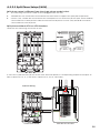
10. Each charging circuit for DELTA Pro needs to feed off a single 30A breaker from the main panel
to enable the fast charge function. If not available, 30A circuit breakers need to be purchased and
installed. The wires corresponding to the PRO charging wires are labeled “PRO1 in” and “PRO2 in”.
If the 30A breaker is not used, the correct current rating should be entered into the app later on to
prevent the circuit breaker tripping from charging current. It is recommended to handle tie both
charging breakers or use a double pole breaker. This makes de-energization of the SHP safer for
future servicing.
Wiring in the Electrical panel
La pagina sta caricando ...
La pagina sta caricando ...
La pagina sta caricando ...
La pagina sta caricando ...
La pagina sta caricando ...
La pagina sta caricando ...
La pagina sta caricando ...
La pagina sta caricando ...
La pagina sta caricando ...
La pagina sta caricando ...
La pagina sta caricando ...
La pagina sta caricando ...
La pagina sta caricando ...
La pagina sta caricando ...
La pagina sta caricando ...
La pagina sta caricando ...
La pagina sta caricando ...
La pagina sta caricando ...
La pagina sta caricando ...
La pagina sta caricando ...
La pagina sta caricando ...
La pagina sta caricando ...
La pagina sta caricando ...
La pagina sta caricando ...
La pagina sta caricando ...
La pagina sta caricando ...
La pagina sta caricando ...
La pagina sta caricando ...
La pagina sta caricando ...
La pagina sta caricando ...
La pagina sta caricando ...
La pagina sta caricando ...
La pagina sta caricando ...
La pagina sta caricando ...
La pagina sta caricando ...
La pagina sta caricando ...
La pagina sta caricando ...
La pagina sta caricando ...
La pagina sta caricando ...
La pagina sta caricando ...
La pagina sta caricando ...
La pagina sta caricando ...
La pagina sta caricando ...
La pagina sta caricando ...
La pagina sta caricando ...
La pagina sta caricando ...
La pagina sta caricando ...
La pagina sta caricando ...
La pagina sta caricando ...
La pagina sta caricando ...
La pagina sta caricando ...
La pagina sta caricando ...
La pagina sta caricando ...
La pagina sta caricando ...
La pagina sta caricando ...
La pagina sta caricando ...
La pagina sta caricando ...
La pagina sta caricando ...
La pagina sta caricando ...
La pagina sta caricando ...
La pagina sta caricando ...
La pagina sta caricando ...
La pagina sta caricando ...
La pagina sta caricando ...
La pagina sta caricando ...
La pagina sta caricando ...
La pagina sta caricando ...
La pagina sta caricando ...
La pagina sta caricando ...
La pagina sta caricando ...
La pagina sta caricando ...
La pagina sta caricando ...
La pagina sta caricando ...
La pagina sta caricando ...
La pagina sta caricando ...
La pagina sta caricando ...
La pagina sta caricando ...
La pagina sta caricando ...
La pagina sta caricando ...
La pagina sta caricando ...
La pagina sta caricando ...
La pagina sta caricando ...
La pagina sta caricando ...
La pagina sta caricando ...
La pagina sta caricando ...
La pagina sta caricando ...
La pagina sta caricando ...
La pagina sta caricando ...
La pagina sta caricando ...
La pagina sta caricando ...
La pagina sta caricando ...
La pagina sta caricando ...
La pagina sta caricando ...
La pagina sta caricando ...
La pagina sta caricando ...
La pagina sta caricando ...
La pagina sta caricando ...
La pagina sta caricando ...
La pagina sta caricando ...
La pagina sta caricando ...
La pagina sta caricando ...
La pagina sta caricando ...
La pagina sta caricando ...
La pagina sta caricando ...
La pagina sta caricando ...
La pagina sta caricando ...
La pagina sta caricando ...
La pagina sta caricando ...
La pagina sta caricando ...
La pagina sta caricando ...
La pagina sta caricando ...
La pagina sta caricando ...
La pagina sta caricando ...
La pagina sta caricando ...
La pagina sta caricando ...
La pagina sta caricando ...
La pagina sta caricando ...
La pagina sta caricando ...
La pagina sta caricando ...
La pagina sta caricando ...
La pagina sta caricando ...
La pagina sta caricando ...
La pagina sta caricando ...
La pagina sta caricando ...
La pagina sta caricando ...
La pagina sta caricando ...
La pagina sta caricando ...
La pagina sta caricando ...
La pagina sta caricando ...
La pagina sta caricando ...
La pagina sta caricando ...
La pagina sta caricando ...
La pagina sta caricando ...
La pagina sta caricando ...
La pagina sta caricando ...
La pagina sta caricando ...
La pagina sta caricando ...
La pagina sta caricando ...
La pagina sta caricando ...
La pagina sta caricando ...
La pagina sta caricando ...
La pagina sta caricando ...
La pagina sta caricando ...
La pagina sta caricando ...
La pagina sta caricando ...
La pagina sta caricando ...
La pagina sta caricando ...
La pagina sta caricando ...
La pagina sta caricando ...
La pagina sta caricando ...
La pagina sta caricando ...
La pagina sta caricando ...
La pagina sta caricando ...
La pagina sta caricando ...
La pagina sta caricando ...
La pagina sta caricando ...
La pagina sta caricando ...
La pagina sta caricando ...
La pagina sta caricando ...
La pagina sta caricando ...
La pagina sta caricando ...
La pagina sta caricando ...
La pagina sta caricando ...
La pagina sta caricando ...
La pagina sta caricando ...
La pagina sta caricando ...
La pagina sta caricando ...
La pagina sta caricando ...
La pagina sta caricando ...
La pagina sta caricando ...
La pagina sta caricando ...
La pagina sta caricando ...
La pagina sta caricando ...
La pagina sta caricando ...
La pagina sta caricando ...
La pagina sta caricando ...
La pagina sta caricando ...
-
 1
1
-
 2
2
-
 3
3
-
 4
4
-
 5
5
-
 6
6
-
 7
7
-
 8
8
-
 9
9
-
 10
10
-
 11
11
-
 12
12
-
 13
13
-
 14
14
-
 15
15
-
 16
16
-
 17
17
-
 18
18
-
 19
19
-
 20
20
-
 21
21
-
 22
22
-
 23
23
-
 24
24
-
 25
25
-
 26
26
-
 27
27
-
 28
28
-
 29
29
-
 30
30
-
 31
31
-
 32
32
-
 33
33
-
 34
34
-
 35
35
-
 36
36
-
 37
37
-
 38
38
-
 39
39
-
 40
40
-
 41
41
-
 42
42
-
 43
43
-
 44
44
-
 45
45
-
 46
46
-
 47
47
-
 48
48
-
 49
49
-
 50
50
-
 51
51
-
 52
52
-
 53
53
-
 54
54
-
 55
55
-
 56
56
-
 57
57
-
 58
58
-
 59
59
-
 60
60
-
 61
61
-
 62
62
-
 63
63
-
 64
64
-
 65
65
-
 66
66
-
 67
67
-
 68
68
-
 69
69
-
 70
70
-
 71
71
-
 72
72
-
 73
73
-
 74
74
-
 75
75
-
 76
76
-
 77
77
-
 78
78
-
 79
79
-
 80
80
-
 81
81
-
 82
82
-
 83
83
-
 84
84
-
 85
85
-
 86
86
-
 87
87
-
 88
88
-
 89
89
-
 90
90
-
 91
91
-
 92
92
-
 93
93
-
 94
94
-
 95
95
-
 96
96
-
 97
97
-
 98
98
-
 99
99
-
 100
100
-
 101
101
-
 102
102
-
 103
103
-
 104
104
-
 105
105
-
 106
106
-
 107
107
-
 108
108
-
 109
109
-
 110
110
-
 111
111
-
 112
112
-
 113
113
-
 114
114
-
 115
115
-
 116
116
-
 117
117
-
 118
118
-
 119
119
-
 120
120
-
 121
121
-
 122
122
-
 123
123
-
 124
124
-
 125
125
-
 126
126
-
 127
127
-
 128
128
-
 129
129
-
 130
130
-
 131
131
-
 132
132
-
 133
133
-
 134
134
-
 135
135
-
 136
136
-
 137
137
-
 138
138
-
 139
139
-
 140
140
-
 141
141
-
 142
142
-
 143
143
-
 144
144
-
 145
145
-
 146
146
-
 147
147
-
 148
148
-
 149
149
-
 150
150
-
 151
151
-
 152
152
-
 153
153
-
 154
154
-
 155
155
-
 156
156
-
 157
157
-
 158
158
-
 159
159
-
 160
160
-
 161
161
-
 162
162
-
 163
163
-
 164
164
-
 165
165
-
 166
166
-
 167
167
-
 168
168
-
 169
169
-
 170
170
-
 171
171
-
 172
172
-
 173
173
-
 174
174
-
 175
175
-
 176
176
-
 177
177
-
 178
178
-
 179
179
-
 180
180
-
 181
181
-
 182
182
-
 183
183
-
 184
184
-
 185
185
-
 186
186
-
 187
187
-
 188
188
-
 189
189
-
 190
190
-
 191
191
-
 192
192
-
 193
193
-
 194
194
-
 195
195
-
 196
196
-
 197
197


EcoFlow Smart Home Panel Combo(13 relay modules) Manuale utente
- Tipo
- Manuale utente
in altre lingue
- English: EcoFlow Smart Home Panel Combo(13 relay modules) User manual
- français: EcoFlow Smart Home Panel Combo(13 relay modules) Manuel utilisateur
- español: EcoFlow Smart Home Panel Combo(13 relay modules) Manual de usuario
- Deutsch: EcoFlow Smart Home Panel Combo(13 relay modules) Benutzerhandbuch
- Nederlands: EcoFlow Smart Home Panel Combo(13 relay modules) Handleiding
Documenti correlati
-
EcoFlow MR500-BC Manuale utente
-
EcoFlow DELTA Pro Manuale utente
-
EcoFlow DELTA Max Manuale utente
-
-
EcoFlow 720Wh RIVER Pro Portable Power Station Manuale utente
-
-
EcoFlow RIVER 2 Guida utente
-
-
EcoFlow RIVER Guida utente
-
EcoFlow 400W Manuale utente
Altri documenti
-
MSW MSW-POWER 700 Manuale del proprietario
-
SPC ATENEA Guida utente
-
Amprobe INSP-3 Manuale utente
-
 Magnum Energy ME2000-20B Manuale del proprietario
-
Magnum Energy MCP5538 Manuale del proprietario
-
Miller KF959177 Manuale del proprietario
-
-
ABB RED650 Applications Manual
-
-
ABB REL650 series Applications Manual
