
Bedienungsanleitung
Operation Manual
Innovation,
die bewegt!
AC
~
DC
=
5222
Steuermodul für Licht-
Einfahrsignal
Control module for colour
light entry signal
1. Wichtige Hinweise / Important information ........................................................ 2
2. Einleitung / Introduction ..................................................................................... 2
3. Anschluss / Connection ..................................................................................... 3
4. Technische Daten / Technical data .................................................................... 7

2
DE EN
1. Wichtige Hinweise
Bitte lesen Sie vor der ersten Anwendung des Produktes bzw. dessen
Einbau diese Bedienungsanleitung aufmerksam durch. Bewahren Sie
diese auf, sie ist Teil des Produktes.
1.1 Sicherheitshinweise
Vorsicht:
Verletzungsgefahr!
Aufgrund der detaillierten Abbildung des Originals bzw. der
vorgesehenen Verwendung kann das Produkt Spitzen, Kanten
und abbruchgefährdete Teile aufweisen. Für die Montage sind
Werkzeuge nötig.
Stromschlaggefahr!
Die Anschlussdrähte niemals in eine Steckdose einführen! Ver-
wendetes Versorgungsgerät (Transformator, Netzteil) regelmäßig
auf Schäden überprüfen. Bei Schäden am Versorgungsgerät
dieses keinesfalls benutzen!
Alle Anschluss- und Montagearbeiten nur bei abgeschalteter
Betriebsspannung durchführen!
Ausschließlich nach VDE/EN gefertigte Modellbahntransforma-
toren verwenden!
Stromquellen unbedingt so absichern, dass es bei einem Kurz-
schluss nicht zum Kabelbrand kommen kann.
1.2 Das Produkt richtig verwenden
Dieses Produkt ist bestimmt:
- Zum Einbau in Modelleisenbahnanlagen und Dioramen.
- Zum Anschluss an einen Modellbahntransformator (z. B. Art.
5200) bzw. an eine Modellbahnsteuerung mit zugelassener
Betriebsspannung.
- Zum Betrieb in trockenen Räumen.
Jeder darüber hinausgehende Gebrauch gilt als nicht bestimmungs-
gemäß. Für daraus resultierende Schäden haftet der Hersteller nicht.
1.3 Packungsinhalt überprüfen
Kontrollieren Sie den Lieferumfang auf Vollständigkeit:
- Steuermodul
- 12 Stecker
- 2 Schrauben
- Anleitung
2. Einleitung
Die Steuermodule für Lichtsignale Art. 5220 bis 5224 von Viess-
mann dienen der einfachen und vorbildgerechten Ansteuerung aller
Viessmann Standard-Lichtsignale. Durch besondere Technik erfolgt
der Wechsel zwischen den einzelnen Signalbildern wie beim Vorbild
fließend (die LEDs glimmen nach). Die Signale werden direkt an den
Steuermodulen angeschlossen.
Um die Ansteuerung der einzelnen LED der Lichtsignale brauchen
Sie sich keine Gedanken mehr zu machen.
Das Steuermodul für Licht-Einfahrsignale Art. 5222 wird über Taster
(z. B. Art. 5546), Gleiskontakte (z. B. Art. 6840 für Baugröße H0) oder
Schaltgleise angesteuert. Über die Buchsen „Vorsignal-Steuerung“
kann ein Steuermodul Art. 5220 für das zugehörige Vorsignal ange
-
steuert werden.
Dieses Vorsignal-Steuerungssystem ist übrigens kompatibel mit der
Vorsignalsteuerung unserer Hobby-Lichtsignale, bei denen sich die
Steuerelektronik im Signalfuß befindet.
Für Licht-Einfahrsignale, bei denen sich ein Licht-Vorsignal mit am
gleichen Mast befindet, benötigen Sie zusätzlich noch das Steuer-
modul für Licht-Vorsignale Art. 5220.
1. Important information
Please read this manual completely and attentively before using the
product for the first time. Keep this manual. It is part of the product.
1.1 Safety instructions
Caution:
Risk of injury!
Due to the detailed reproduction of the original and the intended
use, this product can have peaks, edges and breakable parts.
Tools are required for installation.
Electrical hazard!
Never put the connecting wires into a power socket! Regularly
examine the transformer for damage. In case of any damage, do
not use the transformer.
Make sure that the power supply is switched off when you mount
the device and connect the cables!
Only use VDE/EN tested special model train transformers for
the power supply!
The power sources must be protected to avoid the risk of burning
cables.
1.2 Using the product for its correct purpose
This product is intended:
- For installation in model train layouts and dioramas.
- For connection to an authorized model train transformer (e. g.
item 5200) or a digital command station.
- For operation in dry rooms only.
Using the product for any other purpose is not approved and is con-
sidered inappropriate. The manufacturer is not responsible for any
damage resulting from the improper use of this product.
1.3 Checking the package contents
Check the contents of the package for completeness:
- Control module
- 12 plugs
- 2 screws
- Manual
2. Introduction
The control modules for colour light signals items 5220 to 5224 by
Viessmann are designed to provide a simple means for prototypical
control of all Viessmann standard colour light signals. Special cir-
cuitry enables prototypical transition between signal aspects by first
dimming and then turning off the LED with subsequent soft start of
the LED of the new signal aspect. The signals are to be connected
directly to the control modules.
That is why you do not have to worry about how each individual LED
of a colour light signal is controlled.
The control module for colour light entry signals item 5222 can be oper-
ated with momentary action switches or bell press (e. g. item 5546),
track contacts (e. g. item 6840 for H0 gauge) or switching tracks. A
control module item 5220 for a colour light distant signal can be con-
nected to the sockets “Vorsignal-Steuerung” (= “distant signal control”).
This control system for distant signals is compatible with the control
system for our “Hobby colour light signals” with integral control cir-
cuitry in the base of the signal.
Whenever a colour light distant signal is installed on the same mast
as the entry signal, an additional control module item 5220 for the
colour light distant signal is required.

3
A
ge / ye
4012, 4015,
4412, 4415,
4912, 4915
z. B. / e. g.
5200
16 V AC~
rt / = rot /
gn / = grün /
ge / gelb /
rd red
gn green
ye = yellow
ge / ye
rt / rd
gn / gn
gn / gn
schwarze Markierung
black marking
rt / rd
5222
gelbe Markierung
yellow marking
Diode
diode
rote Markierung
red marking
braun / brown
gelb / yellow
gelber Stecker
yellow plug
brauner Stecker
brown plug
roter Stecker
red plug
grüner Stecker
green plug
grüne Markierung
green marking
gelber Stecker
yellow plug
Sekundär
0-10-16 V~
16 V
Primär
230 V~
Gefertigt nach
VDE 0570
EN 61558
Lichttransformator
5200
Nur für trockene Räume
Primär 230 V 50 - 60 Hz
Sekundär max. 3,25 A52 VA
ta 25°CIP 40
10 V
0 V
Fig. 1
Abb. 1
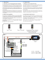
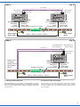
3. Anschluss
3.1 Anschluss von Versorgungsspannung und Signal
Zur Spannungsversorgung ist das Modul über die oben links lie-
genden Buchsen („bn“ und „ge“, d. h. braun und gelb) an den 16
V – Wechselspannungsausgang (Beleuchtungsausgang) eines Mo-
delleisenbahntransformators (z. B. Art. 5200) anzuschließen (Abb. 1).
Das Lichtsignal wird an die unten am Steuermodul befindlichen, mit
den Farben der entsprechenden Signal-LEDs bezeichneten Buchsen
angeschlossen.
Der gemeinsame Rückleiter des Lichtsignals (an dem sich die Diode
befindet) wird an dem Pol der Versorgungsspannung angeschlossen,
welcher mit der braunen Buchse („bn“) des Steuermoduls verbunden
ist (= „Masse“).
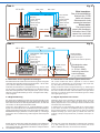
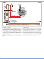
3.2 Abrufen der Signalbilder
Zum Schalten der Signalbilder empfehlen wir unser Tastenstellpult
Art. 5546 (Abb. 2). Es kann jedoch auch jedes Momentkontakt-Tas-
tenstellpult ohne Rückmeldung anderer Hersteller verwendet werden.
Auch ist die Ansteuerung durch Gleiskontakte (z. B. Art. 6840 für H0)
oder Schaltgleise möglich (Abb. 3).
Grundsätzlich ist zu beachten, dass immer gegen die braune
Betriebsspannungsleitung („bn“) des Signalmoduls (= „Masse“)
geschaltet wird.
Es ergeben sich folgende Signalbilder:
3. Connection
3.1 Wiring of power supply and signal
The upper left terminals (“bn” and “ge” – that means brown and yel-
low) have to be wired to the 16 V terminals (lighting output) of a
model train transformer (e. g. item 5200), see fig. 1.
The colour light signal has to be connected with the corresponding
colour-coded sockets located at the bottom of the control module.
These sockets are colour-coded with the corresponding colours of
the signal LEDs.
The common pole of the colour light signal (where the diode is lo-
cated) has to be connected to the brown socket (“bn”) of the control
module resp. the transformer (= “common ground”).
3.2 Activating the signal aspects
For setting the various signal aspects we recommend our push
button panel item 5546 (fig. 2). Any other panel with momentary
contacts without feedback, by other suppliers, can also be used.
The signal can also be operated via track contacts (e. g. item 6840
for H0 gauge) or switching tracks (fig. 3).
Please note that the contacts always have to be connected to the
brown pole (“bn”) of the signal module (= “common ground”).
The possible signal aspects are:
Hp0
"Halt" / "stop"
Hp2
"Langsamfahrt" (max. 40 km/h)
"proceed at reduced speed"
(40 km/h maximum)
Hp1
"Fahrt" / "proceed"

4
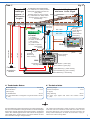
3.3 Anschluss der Vorsignal-Steuerleitungen
Das Steuermodul Art. 5222 ist für die Steuerung eines Vorsignals
vorbereitet. Wir empfehlen hierfür lila farbenes Kabel, z. B. Art. 6867
(10 m) oder Art. 68673 (25 m auf Abrollspule).
Verbinden Sie die Buchsen „Vorsignal-Steuerung“ des Art. 5222
mit der grünen und gelben Eingangsbuchse vom Steuermodul Art.
5220 des vorhergehenden Licht-Vorsignals (Abb. 4) bzw. den lila
farbenen Vorsignal-Steuerleitungen eines vorhergehenden Hobby-
Licht-Vorsignals
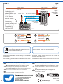
3.4 Zugbeeinflussung
Die Viessmann-Signalsteuermodule sind mit einem Kontakt für die
Zugbeeinflussung ausgestattet. Bei „Halt“-zeigendem Signal (Hp0)
kann damit der Strom am Gleis abgeschaltet werden, so dass die
Lokomotive vor dem Signal automatisch anhält.
Hierzu ist in einem Bereich von ca. 2 Lokomotivlängen vor dem
Signal ein Schienenprofil bzw. bei Märklin-Gleisen der Mittelleiter
mittels Isolierschienenverbindern Ihres Gleissystemherstellers (bzw.
Mittelleiterisolierungen) elektrisch zu trennen (Abb. 6). In der Regel
wird hierzu das in Fahrtrichtung rechts liegende Schienenprofil
gewählt.
3.3 Connection of the distant signal-control wires
The control module item 5222 is prepared to control a distant
signal. For easy identification we recommend to use purple wire,
e. g. item 6867 (10 m) or item 68673 (25 m coil).
Simply connect the sockets “Vorsignal-Steuerung” (= “distant signal
control”) of the item 5222 with the green and yellow input sockets of
the control module item 5220 of the associated colour light distant
signal (fig. 4) or with the purple wires if the distant signal is a “Hobby
colour light signal” (fig. 5).
3.4 Signal dependent train control
Viessmann signal control modules are equipped with a contact for
signal dependent train control. When the signal shows the “stop”
aspect, (Hp0) the track in front of the signal is disconnected and the
locomotive stops automatically.
To achieve this you must electrically isolate (fig. 6) a track section
(or the centre rail contacts of the Märklin tracks) of approximately
two locomotive lengths in front of the signal by means of insulated
fishplates matching your track system (or insulate the centre rail
contacts). Usually the right hand track (in direction of travel) is in-
sulated.
gelber Stecker
yellow plug
5222 5546
braun brown
roter Stecker
red plug
16 V AC~ blau / blue
grüner Stecker
green plug
gelber Stecker
yellow plug
grüner Stecker
green plug
roter Stecker
red plug
Bitte beachten:
Das rückmeldefähige
Stellpult Art. 5548
kann mit diesem
Steuermodul nicht
verwendet werden!
Please note:
The push button
panel with feedback
indication item 5548
cannot be used with
this control module!
blau / blue
blau / blue
Fig. 2
Abb. 2
5222
Signal auf Hp0
("Halt")
signal shows
Hp0 ("stop")
braun / brown
Signal auf Hp2
("Langsamfahrt")
signal shows Hp2
("proceed at reduced speed")
16 V AC~
Schaltgleise oder
Gleiskontakte
(z. B. Art. 6840)
switching tracks or
track contacts
(e. g. Art. 6840)
gelber Stecker
yellow plug
roter Stecker
red plug
grüner Stecker
green plug
Signal auf Hp1
("Fahrt")
signal shows
Hp1 ("proceed")
blau / blue blau / blue
blau / blue
Fig. 3
Abb. 3
Dieses Symbol neben dem Gleis kennzeichnet eine elektrische
Trennstelle (z. B. mit Isolierschienenverbindern) an der gekenn-
zeichneten Gleisseite. Bei Märklin-H0-Gleisen entspricht dieses
iner Mittelleiter-Trennstelle.
This sign next to the track designates an electrical track insulation
(e. g. with insulating track connectors) at the marked side of the
track. For Märklin H0 tracks, this is a third rail insulation.

5
16 V
bn ge
direction of travel
lila / purple
52225220
grüner Stecker
green plug
grüner Stecker
green plug
gelber Stecker
yellow plug
lila / purple
gelber Stecker
yellow plug
400 m, 700 m oder/or 1.000 m
4010, 4030,
4410, 4910
4012, 4412,
4912
steuert dieses
Standard-
Licht-
Vorsignal
controls this
standard
colour light
distant signal
steuert dieses
Standard-
Licht-
Einfahrsignal
controls this
standard
colour light
entry signal
Fig. 4
Abb. 4
gelber Stecker
yellow plug
5222
grüner Stecker
green plug
4012, 4412,
4912
direction of travel
Hobby-Licht-
Vorsignal
Hobby colour
light distant
signal
gelbe Markierung
yellow marking
grüne Markierung
green marking
lila / purple
lila / purple
400 m, 700 m oder/or 1.000 m
steuert dieses
Standard-
Licht-
Einfahrsignal
controls this
standard
colour light
entry signal
Fig. 5
Abb. 5
3.5 Steuermodul und Weiche
Das Signalbild Hp2 („Langsamfahrt“) wird geschaltet, wenn min-
destens eine der folgenden Weichen auf „abzweigen“ gestellt ist.
Abb. 7 zeigt, wie Steuermodul und Weiche gemeinsam geschaltet
werden können.
3.5 Control module and turnout
The signal has to show the Hp2 aspect (“proceed at reduced
speed”) if minimum one of the following turnouts is set to „branch
off“. Fig. 7 shows how you can switch the control module and the
turnout together.

6
A
braun / brown
rot / red
Fahrstrom
propulsion
current
ca. 2 Loklängen
approx. 2 locomotive lengths
rot / red
rot / red
rot / red
direction of
travel
entspricht dem Mittelleiter bei Märklin-Schienen
corresponds to the centre rail of Märklin tracks
Trennstelle
rail insulation
Trennstelle
rail insulation
5222
rote Stecker
red plugs
gelber Stecker
yellow plug
brauner Stecker
brown plug
16 V AC~
Fig. 6
Abb. 6
3.6 Digitale Ansteuerung
Sie können das Steuermodul für Licht-Einfahrsignale auch mit
einem Digitalsystem über einen Magnetartikeldecoder (z. B. Art. 5211
für Märklin-Motorola-Format oder Art. 5280 für das NMRA-DCC-For-
mat) ansteuern (Abb. 8). Wichtig ist, dass der Magnetartikeldecoder
positive Schaltimpulse liefert (d. h. er schaltet gegen „+“)! Außerdem
muss beim Art. 5211 eine Verbindung zwischen Digital-Masse (braun)
und Masse der 16 V - Versorgungsspannung des Steuermoduls
(braun) hergestellt werden.
Bei Art. 5280 beachten Sie bitte Abb. 8. Hier müssen lediglich bei
den blauen Verbindungen Widerstände (1,2 kOhm) eingesetzt
werden.
3.6 Digital control
The control module for colour light entry signals may also be operated
with a digital system. Simply connect the wires to an accessory
decoder (e. g. item 5211 for Märklin-Motorola format or item 5280
for the NMRA DCC format). Also refer to fig. 8. It is important to
know, that the pulses supplied by the accessory decoder have posi-
tive potential (the decoder switches against “+”)! With item 5211 the
common pole of the digital circuit (brown) must be connected with
the common pole of the 16 V supply for the control module (brown).
For item 5280, please observe fig. 8. Only the blue connections
have to be equipped with resistors (1.2 kOhm).

7
schwarze
Markierung
black marking
gelb
yellow
16 V~
AC
grüner Stecker / green plug
braun / brown
braun / brown
rot / red
5222
gelbe Markierung / yellow marking
Diode
diode
grüner Stecker / green plug
Fahrstrom
propulsion
current
rote Stecker
red plugs
rote Markierung / red marking
gelber Stecker
yellow plug
grüne Markierung / green marking
gelber Stecker / yellow plug
roter Stecker
red plug
gelber Stecker
yellow plug
grüner Stecker
green plug
roter Stecker
red plug
5546
braun / brown
blau / blue
gelb / yellow
direction
of travel
geradeaus
straight on
abzweigen
branch off
-
-
ca. 2
Loklängen
approx. 2
locomotive
lengths
Schaltgleise oder Gleiskontakte
(z. B. Viessmann Art. 6840) schalten
das Signal automatsch zurück auf
Hp0 ("Halt")
switching tracks or track contacts
(e. g. Viessmann Art. 6840) switch
the signal back to Hp0 ("stop")
automatically
mind. 1 Zuglänge
minimum 1 train length
1 A - Dioden
(z. B. Viessmann
Art. 6834, 10 Stück)
1 Amp. diodes
(e. g. Viessmann
Art. 6834, 10 pieces)
rot / red
rot / red
blau / blue
blau / blue
Fig. 7
Abb. 7
Das obenstehende Symbol kennzeichnet eine Leitungsverbindung.
Die sich hier kreuzenden Leitungen müssen an einer beliebigen
Stelle ihres Verlaufs elektrisch leitend miteinander in Verbindung
stehen. Der Verbindungspunkt muss nicht exakt an der eingezeich-
neten Stelle sitzen, sondern kann z. B. zu einem Stecker an einer
der kreuzenden Leitungen verlagert werden.
The symbol above designates a cable connection. The cables that
cross here must be in electrical contact with each other at some
point along their length. The connection point does not have to be
exactly at the marked point, but rather can be moved to a plug lo-
cated at one of the crossing cables.
4. Technical data
Operating voltage 16 V AC~
Current consumption 3 mA
(no signal)
during switching 35 mA
For colour light signals with LEDs and common anode
( + - pole)
4. Technische Daten
Betriebsspannung 16 V AC~
Stromaufnahme 3 mA
(ohne Signal)
im Schaltmoment 35 mA
Für LED-bestückte Lichtsignale mit gemeinsamer Anode
(+ - Pol)

Modellbauartikel, kein Spielzeug! Nicht geeignet für
Kinder unter 14 Jahren! Anleitung aufbewahren!
Model building item, not a toy! Not suitable for children
under the age of 14 years! Keep these instructions!
Ce n’est pas un jouet! Ne convient pas aux enfants de moi-
ns de 14 ans! Conservez cette notice d’instructions!
Não é um brinquedo! Não aconselhável para menores de
14 anos! Conservar o manual de instruções!
Modelbouwartikel, geen speelgoed! Niet geschikt voor
kinderen onder 14 jaar! Gebruiksaanwijzing bewaren!
Articolo di modellismo, non è un giocattolo! Non adatto
a bambini al di sotto dei 14 anni! Conservare istruzioni per
l’uso!
Artículo para modelismo ¡No es un juguete! No
recomendado para menores de 14 años! Conserva las
instrucciones de servicio!
DE
EN
FR
NL
IT
ES
PT
Made in Europe
Viessmann
Modelltec
hnik GmbH
Bahnhofstraße 2a
D - 35116 Hatzfeld-Reddighausen
+49 6452 9340-0
www.viessmann-modell.de
Points de collecte sur www.quefairedemesdechets.fr
À DÉPOSER
EN MAGASIN À DÉPOSER
EN DÉCHÈTERIE
OU
Cet modéle
se recycle
FR
FR
8
5211
digitaler
Fahrstrom
digital
propulsion
current
5222
gelber Stecker!
yellow plug!
braun / brown
gelb / yellow
rot / red
16 V AC~
braun / brown
blau mit rotem Stecker
blue with red plug
blau mit gelbem Stecker
blue with yellow plug
blau mit grünem Stecker
blue with green plug
Verbindung zwi-
schen Digital-
Masse (braun) und
Masse (braun) der
16 V - Versor-
gungsspannung
des Art. 5222.
Connection
between digital
ground (brown) und
ground (brown)
from the 16 V
supply voltage of
the item 5222.
braun / brown
rot / red
Fig. 8
Abb. 8
34
1
2
Litzen verdrillen
Twist wires together
Kabel abisolieren
ca. 1,5 cm
Stecker aufschieben
Push plug on
Draht umbiegen
Dismantle the
cable
Bend wire
Änderungen vorbehalten. Keine Haftung für Druckfehler
und Irrtümer.
Die aktuelle Version der Anleitung finden Sie auf der Viess-
mann Homepage unter der Artikelnummer.
Subject to change without prior notice. No liability for
mistakes and printing errors.
You will find the latest version of the manual on the Viess-
mann website using the item number.
Entsorgen Sie dieses Produkt nicht über den
(unsortierten) Hausmüll, sondern führen Sie
es der Wiederverwertung zu.
Do not dispose of this product through (unsorted)
domestic waste, supply it to recycling instead.
92073
Stand 06/sw
05/2023
Ho/Kf
-
 1
1
-
 2
2
-
 3
3
-
 4
4
-
 5
5
-
 6
6
-
 7
7
-
 8
8


in altre lingue
- English: Viessmann 5222 Owner's manual
- Deutsch: Viessmann 5222 Bedienungsanleitung
Documenti correlati
-
Viessmann 5221 Manuale del proprietario
-
Viessmann 5223 Manuale del proprietario
-
Viessmann 5224 Manuale del proprietario
-
-
-
-
-
-
-