Crow RUNNER 8/64 Guida d'installazione
- Categoria
- Impianti citofonici
- Tipo
- Guida d'installazione

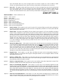
Installation &
Programming Guide
RUNNER 8/64
8/64 Zones Control Panel

This
RUNNER 48/6
alarm control panel has been designed to provide
the most
requested
features for both the installer & the end-user. These features include ease of installation, ease of
programming and user friendly operation all in a package which is reliable, functional and attractive.
Utilising many years of experience in the security industry and implementing valuable feedback, we are
proud to provide you with a new generation of alarm controller. The RUNNER 48/6 is a de-signed
and built product which brings you the quality and features which you deserve at an affordable price.
In addition to the the advanced design, only the highest quality components have been used in the
production of this Alert panel to ensure the highest degree of reliability.
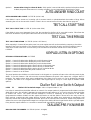
This manual will guide you through the installation and programming of your RUNNER 48/6 alarm
panel. For additional information regarding the operating instructions and options, please refer to the
“RUNNER User’s Guide”.
Revision Feb. D.Z A 2018

Page 3
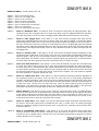
CONTENTS Page No.
CONNECTION DIAGRAM 5
Wiring zone and output expanders to the Panel 5
ZONE EXPANDER DIP SWITCH SETTINGS 6
OUTPUT EXPANDER DIP SWITCH SETTINGS 7
WIEGAND EXPANDER DIP SWITCH SETTINGS 8
SELECTIVE ARM/DISARMING with MULTIPLE AREAS 10
INPUTS 11
Examples of Zone Wiring 12
Inputs 13
Outputs 13
Accessories 14
DTMF COMMAND CONTROL OVERVIEW 14
How to use DTMF Remote Control 14
MEMORY VIEW MODE 15
Current Alarms 15
Historical Memory Events 15
ICON AND FULL LCD KEYPAD INSTALLATION 16
Keypad Address Assignment 16
Keypad Zone or Listen-in Input 16
KEYPAD ADJUSTMENTS 17
Adjusting LCD Keypad Backlighting 17
Adjusting Keypad Buzzer 17
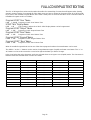
FULL LCD KEYPAD TEXT EDITING 18
Programming LCD User, Display, Output, Area, Keypad Zone Text 18
FULL LCD KEYPAD MENU OPERATION 19
ACCESSING PROGRAM MODE 22
USERS 24
User Codes 24
User Type 24
User Areas 25
User Arm/Disarm options 25
User Program Mode Access 26
Radio User Type & Panic options 26
User Time-zone Control 27
User Keypad assignment 27
User turns Output On or Off 28
Learn/Find and Delete Radio Key Codes 28
Learn/Find and Delete Radio Access Cards 29
MISCELLANEOUS PANEL & CLOCK SETTINGS 30
Installer Code 30
Duress Digit 30
Dial Delay 30
Supervised Detector Timer 30
Two Trigger Time 30
Mains Fail Report Delay 30
Receiver Fail Timer 31
Upload/download Site Code Number 31
Temporary Output Disable 31
Miscellaneous Installer & Panel Options 31
Hide User Codes 33
Setting Time, Date & Daylight Saving 34
OUTPUTS 34
Program LCD Output Name 34
Program Output 1 & 2 Volume 34
Miscellaneous Output Options 35
Output On Delay, Pulse, Reset & Chime Times 37
Output Voice Board Remote Control Start message 37
Un-Map an Output 38
Assigning a Time Zone to an Output 38

Page 4
AREAS 38
Area Arm and Special Function Options 38
Area Arm/Stay Pulse & Chirps to Outputs 39
Area Exit Delay Beeps to Keypads 41
Arm & Stay Exit Delay Time 42
Monitoring Account Code Number 42
Remote Arm/Disarm DTMF Code & Start Voice Message 42
Area Delinquency Time 43
Auto-Arm/Disarm Time-zone 43
Program LCD Area Name 43
KEYPADS 44
Keypad Area Assignment 44
Keypad Button Operations, Misc Beeps and LED Control 44
Keypad “ARM”, “STAY”, “A” & “B” Button Options 45
Keypad Number and “CONTROL” Button to Output Mask 49
Keypad “Panic” “Fire” & “Medical” Alarms to Outputs & KP Buzzer 49
Keypad Chime Timer 49
Full LCD Display Options 51
Program LCD Keypad name 51
ZONES 52
Zone Key Switch Options 52
Zone Area Assignment 52
Zone Alarm Type Options 53
Zone EOL & Vibration Settings 55
Zone Radio Type 56
Zone Alarms to Output & Keypad Buzzer Mapping 58
Armed & Stay Mode Entry Delay Times 60
Zone Lockout Time 60
Various Zone CID Report Codes 60
Zone Inactivity Timer 61
Learn/Find & Delete Radio Zone Codes 61
Program LCD Zone Names 62
TIME-ZONES 62
Time-Zone Days 62
Time-Zone Start & Stop Times 62
DIALLER 63
Enable Dialler and Set Type of Dialling 63
Dialling Cycles, Auto-answer Ring Count 64
Time to First Test Call 64
Keypad Listen-in Options 64
Dialling Pre-fix Number 65
Keypad “Panic” “Fire” & “Medical” Alarms CID Report Code 65
Output, Microphone & Voice Kiss-off DTMF Remote Codes 65
Miscellaneous Voice Reporting Message Numbers 66
TELEPHONE NUMBERS 66
Programming Telephone Numbers 66
Reporting Formats 66
Dial Progress Options 67
Enable/Disable Miscellaneous Dialler Reports 68
IP REPORTING PORT NUMBER 70
SIA REPORTING CODES 71
DIAGNOSTIC & DEFAULT OPTIONS 72
Display Software Version, Keypad Number, Keypad Areas 72
Display Active Time-zones, battery Voltage 72
Start Walk-Test Mode 72
Read or Write to DTU 72
Restore Defaults 73
Clear Memory Buffer 73
PROGRAM SUMMARY GUIDE 75
SPECIAL KEYPAD OPERATING FEATURES 90
QUICK START PROGRAM GUIDE 91
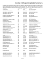
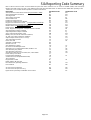
CONTACT ID REPORTING CODE SUMMARY 94
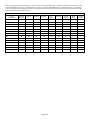
SIA REPORTING CODE SUMMARY 95

Page 5
Line
In
Phone
Out
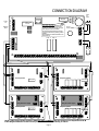
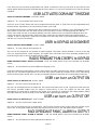
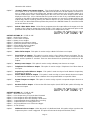
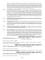
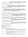
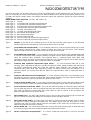
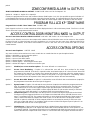
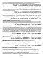
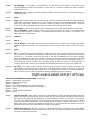
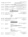
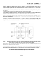
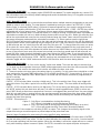
CONNECTION DIAGRAM
LIN DAT CLK NEG POS
RELAY
LINE_OUT
LINE_IN
AC_IN
Outputs
0V 12V 1 2 3 4 0V 12V 1 C 2 3 C 5 4 C 6 7 C 8 TM 0V 12V
NC
EXP 1
RED BLK
Mains
Earth
230V
AC
Input
RUNNER 48/6
V10.00
Bat-
+
_
RST
RESETTING THE PANEL
Power-up the panel with the tamper input in
alarm while shorting out “RST” pins for 5
seconds (you must short out the “RST” pins
before the panel LED starts to flash).
This will Disarm All Armed Areas and allow
access to installer mode by entering <PROG>
<ENTER>.
The Reset feature is disabled if Installer Lock-
out is turned on.
TCP/IP
NO C
SERIAL
EXP 2
17V AC
BATTERY
DIP Switch
- +
13V8IN
TAMP C
0V 12V
OUT
0V 12V
OUT
DAT CLK 0V 12V
OUT
1 2 C 3 4
INPUT
5 6 C 7 8
INPUT
Zone Expander
DAT CLK 0V 12V
OUT
0V 12V
OUT
- +
13V8IN
TAMP C
DIP Switch
Output Expander
NO C NC
RELAY 2
NO C NC
RELAY 3
NO C NC
RELAY 4
NO C NC
RELAY 1
POS
CLK
NEG
DAT
CLK
DAT
CLK
DAT
POS
POS
NEG
NEG
NOTE: If the Plug-in Power supply is fitted DO NOT CONNECT (N/C) the Panel POS to Expander 13.8V IN
If the Wiegand Interface board is used you must follow the same wiring as above.
13.8V
N/C
13.8V
N/C
DIP Switch
- +
13V8IN
TAMP C
0V 12V
OUT
0V 12V
OUT
DAT CLK 0V 12V
OUT
1 2 C 3 4
INPUT
5 6 C 7 8
INPUT
Zone Expander
- +
- +
Plug-in Power supply
12V-24V-AC-AC
0V 12V
OUT
- +
13V8IN
DAT CLK 0V 12V
OUT
TAMP C
DIP Switch
Output Expander
NO C NC
RELAY 2
NO C NC
RELAY 3
NO C NC
RELAY 4
NO C NC
RELAY 1
- +
- +
Plug-in Power supply
12V-24V-AC-AC

Page 6
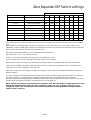
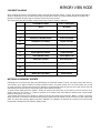
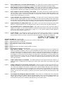
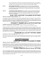
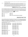
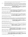
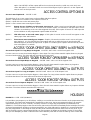
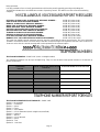
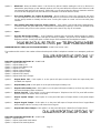
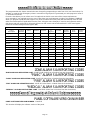
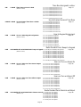
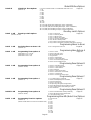
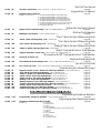
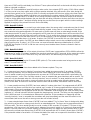
Zone Expander DIP Switch settings
If the zones are set to a type 0-13 then every zone is set to a single zone per input and each zone can be set differ-
ently.
If the Global zone doubling option is turned on at P119E all zones on the panel are set to either a type 14 or 15
(depending on the selected option). When zone doubling is selected every second zone expander is used as per the
above chart as there will be 16 zones per expander not 8.
DIP switch number 8 disables the on-board tamper input if not required.
DIP Switches 4, 5, 6, & 7 are currently unused.
There is an LED associated with every input. They are labelled IP1—IP8.
LED IP1 relates to zone input 1 through to LED IP8 relates to zone input 8.
At power up the LED’s will cycle back and forth until communications is established with the main control panel.
Under normal conditions the LED’s will be off when the zone is sealed and on when the zone is unsealed so the
state of the zone can be displayed at the expander.
If the zone is monitored for a tamper condition (zone types 12, 13 or 14) the associated LED will flash to indicate a
tamper condition.
The zone expander can be powered from the main control panel (as shown on the connection diagram on the previ-
ous page) or there is an optional plug in 1A power supply module that can be fitted to the zone expander.
When the optional power supply module is fitted the 13.8V (POS) from the panel must not be connected, only the 0V
from the main control panel should be connected to the zone expander 0V.
NOTE: If there is an address clash (eg two zone expanders set to the same address number) the 8 LED’s will
display the following pattern, LED’s 1 & 8 On, changing to LED’s 2 & 7 On, changing to LED’s 3 & 6 On,
changing to LED’s 4 & 5 On, then all 8 LED’s will flash together twice then the pattern will repeat until the
address clash is removed.
Expanders - Zone Doubling Expanders - NO Zone Doubling 1 2 3 4 5 6 7 8
Not used
EXP # 1 (zones 9-16) ON
off off
EXP # 2 (zones 17-32) EXP # 2 (zones 17-24)
off
ON
off
Not used
EXP # 3 (zones 25-32) ON ON
off
EXP # 4 (zones 33-48) EXP # 4 (zones 33-40)
off off
ON
Not used
EXP # 5 (zones 41-48) ON
off
ON
EXP # 6 (zones 49-64) EXP # 6 (zones 49-56)
off
ON ON
Not used
EXP # 7 (zones 57-64) ON ON ON
On Board Tamper Ignored ON
On Board Tamper Active
off
DIP Switch #

Page 7
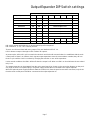
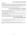
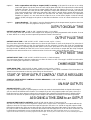
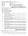
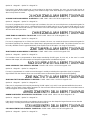
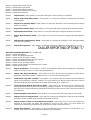
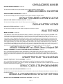
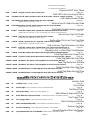
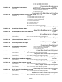
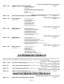
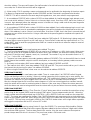
Output Expander DIP Switch settings
DIP switch number 8 disables the on-board tamper input if not required.
DIP Switches 4, 5, 6, & 7 are currently unused.
There is an LED associated with every output. They are labelled OUTPUT 1-4.
LED 1 relates to output 1 through to LED 4 relates to output 4.
At power up the LED’s will cycle in numerical order back and forth until communications is established with the main
control panel. If there is an address clash (eg two output expanders set to the same address number) they will con-
tinue to cycle until the clash is resolved by changing the switches on one of the expanders.
Under normal conditions the LED’s will be off when the output is off. When an LED is on that indicates the associated
relay is on.
The output expander can be powered from the main control panel (as shown on the connection diagram on the previ-
ous page) or there is an optional plug in 1A power supply module that can be fitted to the output expander.
When the optional power supply module is fitted the 13.8V (POS) from the panel must not be connected, only the 0V
from the main control panel should be connected to the output expander 0V.
DIP Switch #
Output Expander Number 1 2 3 4 5 6 7 8
O/P EXP # 1
off off off
Follows Outputs 1-4
O/P EXP # 2 ON
off off
Follows Outputs 5-8
O/P EXP # 3
off
ON
off
Follows Outputs 9-12
O/P EXP # 4 ON ON
off
Follows Outputs 13-16
O/P EXP # 5
off off
ON Follows Outputs 17-20
O/P EXP # 6 ON
off
ON Follows Outputs 21-24
O/P EXP # 7
off
ON ON Follows Outputs 25-28
O/P EXP # 8 ON ON ON
On Board Tamper Ignored ON
On Board Tamper Active
off
Follows Outputs 29-32

Page 8
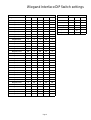
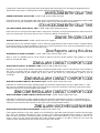
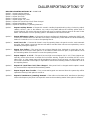
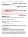
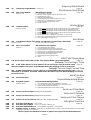
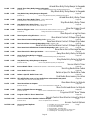
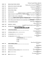
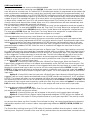
Wiegand Interface DIP Switch settings
DIP Switch #
Wiegand Interface Address 1 2 3 4 5
Wiegand I/F # 1
off off off off off
Wiegand I/F # 2 ON
off off off off
Wiegand I/F # 3
off
ON
off off off
Wiegand I/F # 4 ON ON
off off off
Wiegand I/F # 5
off off
ON
off off
Wiegand I/F # 6 ON
off
ON
off off
Wiegand I/F # 7
off
ON ON
off off
Wiegand I/F # 8 ON ON ON
off off
Wiegand I/F # 9
off off off
ON
off
Wiegand I/F # 10 ON
off off
ON
off
Wiegand I/F # 11
off
ON
off
ON
off
Wiegand I/F # 12 ON ON
off
ON
off
Wiegand I/F # 13
off off
ON ON
off
Wiegand I/F # 14 ON
off
ON ON
off
Wiegand I/F # 15
off
ON ON ON
off
Wiegand I/F # 16 ON ON ON ON
off
Wiegand I/F # 17
off off off off
ON
Wiegand I/F # 18 ON
off off off
ON
Wiegand I/F # 19
off
ON
off off
ON
Wiegand I/F # 20 ON ON
off off
ON
Wiegand I/F # 21
off off
ON
off
ON
Wiegand I/F # 22 ON
off
ON
off
ON
Wiegand I/F # 23
off
ON ON
off
ON
Wiegand I/F # 24 ON ON ON
off
ON
Wiegand I/F # 25
off off off
ON ON
Wiegand I/F # 26 ON
off off
ON ON
Wiegand I/F # 27
off
ON
off
ON ON
Wiegand I/F # 28 ON ON
off
ON ON
Wiegand I/F # 29
off off
ON ON ON
Wiegand I/F # 30 ON
off
ON ON ON
Wiegand I/F # 31
off
ON ON ON ON
Wiegand I/F # 32 ON ON ON ON ON
DIP Switch #
OPTION 6 7 8
1 Door Cntrl
off
- -
2 Door Cntrl ON - -
CPT-Wiegand -
off off
PW READER - ON
off
Spare -
off
ON
Spare - ON ON

Page 9
INSTALLING PROXIMITY READERS
The Wiegand Interface board allows various access control readers/keypads to be connected to the RUNNER 648/
key-pad bus.
The Wiegand Interface has an 8 way DIP switch that allows the keypad address to be set to a value between 1-32.
It also has two inputs and a relay output that are linked to the keypad address, eg if the Wiegand Interface board is
set to keypad address number 15 (Switches 2, 3 & 4 ON) then input 1 can become zone 15 on the control panel
(provided option 4, “zone is a keypad zone”, is
turned on at panel program address P122E15E) and relay 1 will fol-
low output 15 from the control panel.
This allows the input to be used for door monitoring or as a REX (request to exit) input that is controlled by the main
panel.
It also allows the door control relay (output 1 on the Wiegand Interface) to be controlled by the main panel.
There is also two LED outputs for each reader port labelled LD1 & LD2. LD1 is preset to follow the status of the as-
sociated relay on the board, eg LD1 on wiegand interface 1 will follow relay
1.
LD2 has two functions.
The first is it gives a single flash when any card is presented or a button on the keypad is pressed.
The second is LD2 can be programmed to follow an output on the panel at program address P98E so that when the
output is on LD2 will also be on to drive the LED on the reader. This can be used to indicate an arm/disarm state,
etc.
The Buzzer output on the Wiegand reader connections will follow the keypad beeps from the panel. If the Wiegand
keypad has a built-in numeric keypad the Buzzer output (BUZ) will beep as a button is press
ed as audible feedback
that the button was received by the panel. The same Buzzer output can also follow other beeps from the panel such
as entry or exit delay beeps, chime zone beeps, etc.
DIP switch 6 sets the Wiegand Interface to be a single door or two door controller. If DIP switch 6 is off the board is
a single door controller and only Wiegand interface 1 is used for the reader input. Input 1 can be linked to the zone
number that matches the keypad address
of the board and output 1 is linked to the output number that matches the
keypad address. Also when DIP switch 6 is off, input two is linked to relay 1. If input 2 is triggered the output reset
time programmed for the output associated with relay 1 will operate relay 1 for that timed period. Input 2 can there-
fore be used as a request to exit button.
If DIP switch 6 is on then both reader interfaces are used and both inputs and outputs are active. The second reader
will be the address set by switches 1-5 plus 1, eg if the board address is set to number 12 (DIP switches 1, 2 & 4
ON) then reader interface 1 will be keypad address 12 and reader interface 2 will be keypad address 13. In the
same example input 1 on the Wiegand interface can be set to zone 12 and input 2 set to zone 13, output 1 on the
Wiegand interface will follow output 12 and output 2 will follow output 13.
NOTE: Always ensure DIP Switch 6 is OFF if the board is to only use one keypad address otherwise there
could be a keypad address clash, eg if one Wiegand IF board is addressed as keypad # 10 and another as
keypad address # 11 but DIP switch 6 was turned ON on the board set as keypad # 10 there will be a clash
due to there being two keypad # 11’s, one will be the second reader input on the board set as address # 10
and the other will be the board set as keypad address # 11.
NOTE 2: If there is an address clash (eg two Wiegand IF boards set to the same address number) the 8
LED’s will display the following pattern, LED’s 1 & 8 On, changing to LED’s 2 & 7 On, changing to LED’s 3 &
6 On, changing to LED’s 4 & 5 On, then all 8 LED’s will flash together twice then the pattern will repeat until
the address clash is removed.
DIP switches 7-8 allow the type of access
control technology to be selected (see chart on page 8).There are two
proximity readers that can be connected to the control panel. They are;
1-CPT-Wiegand reader/keypad
2-PW READER Prox/PIN readers.
E
ach Wiegand Interface board must have a unique keypad address number from 1-32 to avoid data conflicts and to
allow assigned program options to be directed to the correct unit.

Page 10
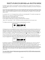
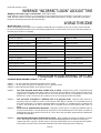
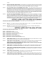
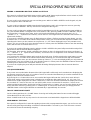
SELECTIVE ARM/DISARMING with MULTIPLE AREAS
At software version V225 a new method for selective arm/disarm when multiple areas are assigned to a
user was added to make it more flexible. To use this new selective arm/disarm you must turn ON option 6
at P25E13E.
If a user has many assigned areas they can chose to select which area or areas they would like to arm or
disarm. The areas assigned to the user must have “ARM Before Code” selected for all of the areas (P45E
option 1 ON) and all areas assigned to the user must be assigned to their keypad (P71E) and the ARM
button (P74E).
For example User 1 has 10 assigned areas and they are using Keypad # 1. The options to program are:
P2E1E User 1 has areas 01,02,03,04,05,06,07,08,09,10.
P45E1-10E Areas 1-10 have option 1 ON.
P71E1 Keypad 1 has areas 01,02,03,04,05,06,07,08,09,10.
P74E1 Keypad 1 “ARM” button has areas 01,02,03,04,05,06,07,08,09,10
When User 1 enters ARM - CODE - ENTER they will be presented with a list of areas to arm.
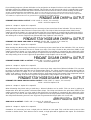
The display would look like this (only 6 areas can be displayed at one time):
All displayed areas are highlighted so they are ready for Arming. Below this selection line will be the cus-
tomised text name for the currently selected area (eg if area 01 was named “Reception PIR” that name
will appear underneath the selected area number). The currently selected area is area 01 because it is
inside the >< brackets. To select the next area and also see the other areas press the “BYPASS “ but-
ton to move the display to the right. To move back press the “ “ button to move back to the left.
If all the selected areas are to be armed simply pres the “ENTER” button to start arming of all areas.
To remove an area you can press the “ARM” button when the required area is selected. It will change to
being un-highlighted as shown in the example below where area 01 was removed from the arming list.
By default all assigned areas will be highlighted meaning they are all going to arm. If the user wants to
reverse that selection so that all areas are not highlighted (eg none will arm) they can press 00. To
change it back the user can press 99 to select ALL areas again. If a user has a large number of areas as-
signed but they only want to arm a few of them they can press 00 to deselect all areas then use the
“ARM” button to select the few they want to arm. If they want to arm most of the areas but exclude just a
few they would start off with all areas selected (99) then simply deselect the few they don’t want using the
“ARM” button. Once the selection has been made they simply press the ENTER button to arm the se-
lected areas.
The same situation works for disarming only the user presses CODE - ENTER and they are presented
with a list of areas to disarm. The selection toggle with the “ARM” button and the 00 & 99 functions work
the same during disarm.
Area/s to arm
> <
Reception PIR
01 02 03
06
05 04
Area/s to arm
> <
Reception PIR
01 02
03
06 05 04

Page 11
2k2
Tamper
4k7 8k2
Tamper
Alarm or Key-switch 1 Contact
Alarm or Key-switch 2 Contact
NC or NO NC or NO
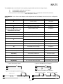
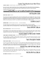
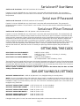
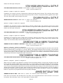
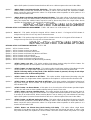
INPUTS
The RUNNER 48/6 control board has 9 separate programmable monitored analogue inputs,
8 x Programmable, multi-state z
one inputs
1 x Programmable tamper input
Each input must be terminated with the appropriate value or combination of end-of-line resistors,
even if the input is unused.
ZONE INPUTS - Each of the 8 zone inputs can be assigned one of the following End of Line (EOL) configuration
options,
Zone EOL Type (P125E) Input Resistor Comments
0 (Short circuit) Loop EOL
1 1k (Brown, Black, Red) Single EOL
2 1k5 (Brown, Green, Red) Single EOL
3
(P126E “Vibration Mode” only
supports this EOL value)
2k2 (Red, Red, Red) Single EOL
4
3k3 (Orange, Orange, Red) Single EOL
5
3k9 (Orange, White, Red) Single EOL
6 4k7 (Yellow, Violet, Red) Single EOL
7 5k6 (Green, Blue, Red) Single EOL
8 6k8 (Blue, Grey, Red) Single EOL
9 10k (Brown, Black, Orange) Single EOL
10 12k (Brown, Red, Orange) Single EOL
11 22k (Red, Red, Orange) Single EOL
12 (series) 2k2 Tamper, 4k7 Zone Zone & Tamper
13 (series)
3k3 Tamper, 6k8 Zone Zone & Tamper
14 (series)
2k2 Tamper, 4k7 Low Zone, 8k2 High Zone Zone Doubling, with Tamper
15 (series) 4k7 Low Zone, 8k2 High Zone Zone Doubling, No Tamper
16 (parallel) 4k7 Low Zone, 8k2 High Zone Zone Doubling, No Tamper
Type 1-11 (Single EOL no Tamper)
Type 14 (Zone Doubling with Tamper)
n/c
n/o
EOL Resistor
Type 0 (Short/Loop Circuit)
n/c
Type 12-13 (Single Zone with Tamper)
2k2 or 3k3
Alarm Contact
n/c or n/o
4k7 or 6k8
Tamper Resistor

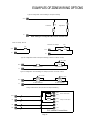
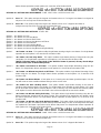
Page 12
Zone
0V
N/C
Short circuit loop, No EOL
N/C
Zone
0V
2k2 EOL, No Tamper
2k2
N/O
2k2
0V
Zone
Type 12 Configuration. Alarm & Tamper monitoring (contacts can be N/C or N/O)
4k7
N/C or N/O
Zone Resistor Tamper Resistor
0V
Wiring a PIR Detector (N/C) for Alarm & Tamper Monitoring
Zone
2k2
4k7
Alarm Contact (N/C)
PIR Internal Connections
Alarm
Tamp
Tamp
Alarm
0V
+12V
Tamper Contact (N/C)
0V
12V
EXAMPLES OF ZONE WIRING OPTIONS
Type 15 Configuration. Zone Doubling, NO Tamper (contacts can be N/C or N/O)
4k7
0V
Zone
N/C or N/O
Lo-Zone Resistor Hi-Zone Resistor
N/C or N/O
8k2
Type 16 Configuration. Zone doubling no Tamper monitoring
0V
Zone
8k2
N/C
High Zone
4k7
Low Zone
N/C
NOTE: With Type 16 configuration NO contacts cannot be used

Page 13
INPUTS cont.
TAMPER - A 24Hr tamper circuit is available for monitoring system tampers. This Tamper circuit is programmable
as either normally closed loop or 2k2 EOL supervision (the default is normally closed loop). Any Tamper alarms on
this input are mapped to alarm outputs in the same manner as for detection zones.
In addition to the Zone & Tamper inputs, you will find the following additional inputs on the control PCB;
AC - Connect the 17VAC yellow wires (no polarity) from the transformer to the terminals marked AC on the PCB.
The panel includes a mains transformer rated at 1.4 amps at 17 VAC.
EARTH - Connect the mains earth to the appropriate terminal on the mains terminal block in the control box
cabinet. Also connect a lead from this earth point to the terminal marked with the Earth symbol (next to AC
terminals) on the panel PCB.
BATTERY - Connect a sealed lead acid rechargeable 12VDC battery to the terminals labelled red and black on the
control panel being careful to observe the correct polarity. The minimum recommended battery capacity is 7 amp
hours. Battery charge current at these terminals is limited to 300mA maximum. The battery connection is protected
against short circuits by a thermal fuse. The panel performs a dynamic load test on the battery every 15 seconds
and if it fails the test at any time it will indicate a battery low condition.
LINE IN - These terminals are used to connect the panel to the incoming telephone line. The dialler uses this line
for reporting alarm events. An ADSL filter will be required before the Line In terminals if ADSL is present in the
building.
LINE OUT - These terminals are used to connect telephones and other communication equipment to the incoming
phone line via the panel dialler circuit. The telephone line is passed through the controller to ensure that the line is
available to the controller when it is required.
OUTPUTS
12 VOLT OUTPUTS - There are three 12VDC outputs on the panel PCB. These 12 volt outputs are regulated and
Thermal fuse protected against short circuits. The accessory outputs are marked 12V and 0V, while the keypad
buss 12V supply is labelled “POS” & “NEG”. The 12V outputs are supplied by thermal fuses. The recommended
maximum total load that should be drawn from all of the 12V outputs is 1A.
OUTPUTS 1 & 2 - These fully programmable, high current, open drain (high-going-low) type FET outputs capable
of switching up to 1.5A @ 12VDC. These 2 outputs are normally set as switched outputs, providing power for 12V
sirens or piezos. If required, these outputs can be programmed to be siren outputs designed to drive an 8 ohm 10
watt horn speaker on each output (see P37E option 1). If an inductive load is connected to these outputs a back
EMF diode should be fitted.
OUTPUT 3&4 - These are medium current, open drain (high-going-low) type FET outputs capable of switching up
to 1A. Like Outputs 1 & 2 they are fully programmable. If an inductive load is connected to these outputs a back
EMF diode should be fitted.
NOTE: - Connecting devices that draw current in excess of 1A to outputs 3 or 4 will damage the output.
OUTPUT 4 Relay - This is a relay output (rated 1A@30VDC) that works in parallel with the FET on output 4. It has
single pole changeover contacts. Like Outputs 1 & 2 it is fully programmable.
KEYPAD PORT - The terminals marked POS, NEG, CLOCK, & DATA make up the communications port which the
keypads and other intelligent field devices use to talk to the controller. The terminals are connected to
corresponding terminals on the remote devices. The "lin" terminal is only used by the keypads and utilises a fifth
wire to provide a communicator “listen-in” facility. This feature is particularly useful when servicing monitoring
faults. The keypad 12V supply (POS,NEG) is protected by a thermal fuse.
EXPANSION PORTS - There are two high speed expansion ports (labelled EXP1 & EXP2) plus one 9600 baud
serial port (labelled SERIAL). The serial port has no function at present and is provided for possible future use. The
two expansion ports allow optional devices such as the Cellular back-up module, CAN bus interface and other
peripherals to come later.
ETHERNET PORT - The on-board Ethernet port allows upload/download via the built-in web page, IP monitoring
and remote control via Smartphone and tablet apps.

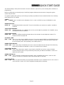
Page 14
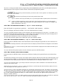
ACCESSORIES
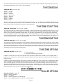
DTMF COMMAND CONTROL SEQUENCE
If DTMF Command Control has been enabled the operation is performed as follows.
Call the control panel.
When the panel answers it will play the message “Enter your code followed by the # key”.
A
t that point enter in your DTMF Code (program location P63E for Area Arm/Disarm or P175E12E for Output control)
fo
llowed by the # key on the phone.
DTMF Arming and Disarming
If for example the DTMF code to remotely arm and disarm Area 1 (P63E1E) was 1234 and Area 1 was disarmed,
when you enter the Area 1 DTMF code;
1234 # - (you will hear the message “Area 1 Disarmed”)
If you then press the * key it will change the state or Area 1, eg
* - (you will hear the message “Area 1 Armed”)
DTMF Output Control
If for example the DTMF code to remotely control Outputs (P175E12E) was 9876 and you were controlling Output 1
(which was currently Off), when you enter the Output DTMF code followed by output 1 (01);
9876 01 # - (you will hear the message “Output 1 Off”)
If you then press the * key it will change the state of Output 1, eg
* - (you will hear the message “Output 1 On”)
Exiting DTMF Control Mode
When all DTMF remote control functions are completed you can either hang up the phone and the control panel will
hang up automatically in 15 seconds or you can press;
00 # - (you will hear “Goodbye”) and the panel will hang up immediately.

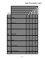
Page 15
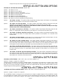
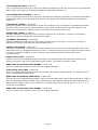
MEMORY VIEW MODE
CURRENT ALARMS
When viewing the memory event buffer at the keypad by pressing the “MEMÇ” button, the first thing that will al-
ways be displayed are any Current Alarms that are still active. When all current system alarms have been dis-
played the keypad will then start to show the historical memory events.
The chart below lists the possible current alarms that could be shown in memory.
HISTORICAL MEMORY EVENTS
Following the “Current Alarms” the panel will display the historical memory events. The panel stores the most re-
cent events, (up to approx 12000), including all alarm events, all system events such as mains failure etc as well
as arming by Area. The memory events are displayed chronologically with the most recent event shown first and
subsequent events following in descending order from newest to oldest.
To view events simply press the “MEMÇ” button to move to the next event. If you wish to go back and look at an
earlier event you can use the “È” button to go back to an earlier event. Each time the Down arrow is pressed the
memory will go back one event.
The keypad will beep and the display is advanced to the next event every time the “MEMÇ” button is pressed.
When all events in memory have been displayed the keypad will exit memory mode and return to the normal idle
state. To cancel the memory display just press “ENTER”. If no buttons are pressed for a period of 20 seconds the
keypad will automatically exit memory display mode.
CURRENT ALARMS FULL LCD Display
None
No Faults
1 Mains Failure Power Failure
2 Battery Low Battery Low
3 12V Fuse or Output Failure O/P or Fuse Fail
4 Telephone Line Failure Phone Line Fail
5 Radio Detector Battery Low Radio Batt Low
6 Radio Pendant Battery Low Pendant Batt Low
7 Zone Supervise Failure Supervised Fail
8 SensorWatch Alarm SensorWatch Fail
9 Delinquency Alarm Area Delinquency
10 Keypad Missing/Fault Keypad Missing
11
12
13
Dialler Kiss-off Failure
Dialer Failure

Page 16
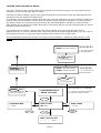
FULL LCD KEYPAD INSTALLATION
INSTALLATION
Connect the 4 wires from the keypad bus on the main control panel to the corresponding connections on the keypad
(DAT, CLK, POS & NEG) The 5th wire is an optional “Listen-in“ connection. It is connected from the "Input" terminal
of the keypad to the "Lin" terminal of the panel keypad port. With the Listen-in wire connected the user can hear the
call progress during dialling at the keypad (provided the desired program options at address P175E 6E are turned
on). The keypad input must not be set as a zone (P122E option 4) for the listen-in feature to work.
The maximum recommended cable distance using standard 0.2mm security cable is 50m, or 100m using 0.5mm se-
curity cable. For longer cable runs there is a keypad bus extender module available.
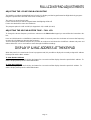
FULL LCD KEYPAD ADDRESS ASSIGNMENT
A total of 32 devices (keypads or wiegand interface modules) can be connected to the panel. Each keypad must be
addressed individually to avoid BUS conflicts when multiple users are operating different keypads simultaneously. By
default, each keypad comes addressed as KP # 1.
Setting the LCD keypad address is done in “Local Program Mode”.
To enter “Local Program Mode” on the FULL LCD Keypad you must press <PROGRAM> then <BYPASS> then
<ENTER> (sequential button entry). The display will show “keypad number” and the currently assigned keypad ad-
dress number will be shown.
By pressing any number from 01-32 then pressing <ENTER> the keypad will change it’s address to the new entry
and automatically exit Local program mode.
If you do not assign a unique address to every keypad and reader connected to the keypad buss, a conflict
will exist that will cause erratic operation. Each reader or keypad MUST have a different address.
FULL LCD KEYPAD ZONE INPUT
On the FULL LCD keypads there is a spare terminal labelled “Input”.
This input can be used for listening in when the dialler is active or as a zone input linked back to the main panel.
The zone associated with the keypad input is linked to the keypad address, eg if the keypad address is set to 23 the
input on the keypad will be linked to zone 23.
If the zone input at P122E has option 4 turned off the keypad input is used for the listen in function.
If option 4 is turned on the input will work as the associated zone input, eg if the keypad address is set to 23 and op-
tion 4 is turned on at P122E 23E the keypad input will work as zone 23 sending sealed and unsealed status back to
the panel.

Page 17
FULL LCD KEYPAD ADJUSTMENTS
ADJUSTING THE LCD KEYPAD BACKLIGHTING
The installer can adjust the backlight level of each LCD display and the keypad button backlight levels by program-
ming the required value at P95E in the main control panel.
The value is a range from 0-100%.
If set to 0 both the LCD and the keypad button backlighting will be off.
If set to 100 both will be set to the maximum.
The program option is P95E 01-32E (for keypad # 1-32) 0-100E (0-100%)
ADJUSTING THE KEYPAD BUZZER TONE – FULL LCD
To change the buzzer frequency and hence volume on the FULL LCD Keypad you must follow the instructions be-
low;
Press and hold down the <CONTROL> button then within 2 seconds press the <1> button to increase the frequency
or press the <2> button to decrease the frequency.
To move through the different frequencies you have to continue to hold down the <CONTROL> button and press and
release either the <1> or <2> button to move through the different settings.
DISPLAY IP & MAC ADDRESS AT THE KEYPAD
When the panel is in normal mode (ie not in program mode) it is possible to display the currently assigned IP address
for the panel and the MAC address.
To view the MAC Address
At the LCD keypad press and hold the <8> button for 4 seconds until the display shows the panels MAC address. To
exit the display mode press the <ENTER> button.
To view the IP Address
At the LCD keypad press and hold the <9> button for 4 seconds until the display shows the panels IP address. To
exit the display mode press the <ENTER> button.

Page 18
FULL LCD KEYPAD TEXT EDITING
The FUL LCD keypad has various text locations that allow for customising of names that will appear when viewing
events in memory mode. For example all of the 2000 users can have a unique 20 character name. All LCD Text edit-
ing is done in the “Installer Program Mode” at the main control panel. A list of the text that can be customised when in
Installation Program mode is as follows;
Program LCD KP “User “Name
P16E 1-2000E Program LCD KP “User” Name Text
LCD KP “Idle” Display Name
P25E 14E This location is where the LCD KP “Idle” Display Name can be Programmed.
Program LCD KP “Output” Name
P31E 1-32E Program LCD KP “Output” Name Text
Program LCD KP “Area” Name
P69E 1-32E Program LCD KP “Area” Name Text
Program LCD KP “Keypad” Name
P100E 1-32E Program LCD KP “Keypad” Name Text
Program LCD KP ” Zone” Name
P169E 1-64E Program LCD KP “Zone” Name Text
When in Installer Program Mode and at one of the above program locations the arrow buttons can be used.
The “MEMÇ” or the “È” buttons can be used to change between upper (Capital) and lower case letters. The “Å” or
“Æ” buttons can be used to move the cursor left or right to the letter you wish to change.
In the chart below the main characters are those selected when set to Upper case (Capital) mode. The characters in
brackets are those selected when in lower case mode.
▼Button # 1st Press 2nd Press 3rd Press 4th Press
1 * (‘) # (<) = (>) 1
2 A (a) B (b) C (c) 2
3 D (d) E (e) F (f) 3
4 G (g) H (h) I (i) 4
5 J (j) K (k) L (l) 5
6 M (m) N (n) O (o) 6
7 P (p) Q (q) R (r) 7
8 S (s) T (t) U (u) 8
9 V (v) W (w) X (x) 9
0 Blank Y (y) Z (z) 0

Page 19
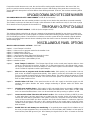
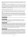
FULL LCD KEYPAD MENU PROGRAMMING
The FULL LCD Keypad enables “Menu” programming of the RUNNER 48/6 panel. Easy to follow plain text Menus
will be displayed on the keypad to enable selection of the desired programming options.
<ENTER> key selects the Menu you wish to work in or the option in a Sub-Menu you wish
to use.
<PROG> key will step you back to the previous Menu level.
ÇÈ <Up> or <Down> arrow keys will allow you to cycle through the Menu options (Main & Sub Menus).
ÅÆ <Left> or <Right> arrow keys can be used when in the Data Entry-Menus to cycle through the
options (eg if in “USERS” Data Entry-Menu, the options would be Users 1-2000, if in “ZONES” the
options would Zones 1-64, etc).
SELECTING THE MAIN-MENU HEADINGS (“Ç Up” or “È Down” Arrow Keys)
Ente
r “INSTALLER” Program Mode eg <PROG> - <INSTALLER CODE (000000)> - <ENTER>.
The LCD will display “INSTALLER:USERS”. This is the default Main-Menu heading.
To access a desired program location you first navigate to the desired Main-Menu by using the “Ç Up” button to cy-
cle forward through the menu headings (the “È Down” button moves backwards through the menu headings). Each
press of “Ç Up” button will advance the display to the next Menu heading.
The Main-Menu h
eadings are shown on the top line of the LCD display.
To access the Sub-Menu options from a Main-Menu press the <ENTER> button.
SELECTING THE SUB-MENU HEADINGS (“Ç Up” or “È Down” Arrow Keys)
Ha
ving pressed the <ENTER> button at the selected Main-Menu heading the keypad will now show Sub-Menus for
that
heading.
The Main-Menu heading will remain on the top line of the LCD display and the Sub-Menus will appear on the bottom
line.
E
ach press of “Ç Up” or “È Down” arrow keys will advance the Sub-Menus displayed on the bottom line either up or
down by one location.
To access the Data Entry-Menu options from the Sub-Menu press the <ENTER> button.
SE
LECTING THE DATA ENTRY-MENU HEADINGS
Having pressed the <ENTER> button at the desired Sub-Menu heading, the keypad will now be in the Data Entry-
Mode.
The Main-Menu heading on the top line of the display will be replaced with the actual data entry field description, eg if
you had gone from “USERS” to “CODES” then to the data entry field of codes the display will show “USER CODE 1”
on the top line of the display and the code “123” on the bottom line (“123” being the default User 1 code).
Y
ou can now change the code, eg to change Code # 1 to 4567 press <4567> <ENTER>. The bottom line will now
show
the new code of “4567”.
At this point you can use the “Ç Up” or “È Down” arrow keys to cycle through the other Sub-Menu options for User
Code 1 to program all of the options for code 1, or;
You
can use the “Å Left” or “Æ Right” arrow keys to cycle through all of the User codes. This allows you to program
a
ll of the user codes from 1-2000. The “Æ Right” arrow key when pressed will take you up one User at a time and the
“Å Left” arrow key will take you down one User, eg if the display was currently showing “USER CODE 10”, pressing
the “Å Left” arrow key will take the display to “USER CODE 9”, pressing the “Æ Right” arrow key will take the
display to “USER CODE 11”.
You can also use the “Å Left” or “Æ Right” arrow keys to move through all of the User codes, and while at a particular
Us
er, you can also use the “Ç Up” or “È Down” arrow keys to program all options for that User.
ENTER
PROG

Page 20
STEPPING BACK THROUGH THE MENUS
If you are in a Menu location, eg the “USER” Data Entry field, and you wish to step back one stage to the previous
Sub-Menu, you need to press the <PROG> button.
Each time the <PROG> button is pressed the display will step back to the previous stage (remembering where you
were before) until you get back to the Main-Menu.
For example if you were in the “KEYPADS” Main-Menu, then pressed <ENTER> to get to the “AREAS” Sub-Menu for
keypads, then pressed <ENTER> again to get to the “AREAS” Data Entry-Menu for keypads, you could now press
the <PROG> button once and it would take you back to the “KEYPADS/AREAS” Sub-Menu. Pressing <PROG>
again will take you back to the “KEYPADS” Main-Menu, and pressing <PROG> one more time will return you back to
the default “USERS” Main-Menu.
If you get back to the “USERS” menu and press the <PROG> button once more the display will go to the
program exit menu. If you press <ENTER> when at this point the panel will leave program mode. If you don’t wish to
leave program mode you can press the <PROG> button again to return to the “USERS” menu.
The flowchart below indicates the program menu steps using the “ARROW” , “ENTER” & “PROG” Buttons on the
keypad.
Ç orÈ Arrows will Cycle
through Main-Menus
MAIN-MENU
SUB-MENU
Ç orÈ Arrows will Cycle
through Sub-Menus
DATA ENTRY-MENU
USER 1 CODE
123 (Data)
USER 2000 CODE
— (Data)
USER 2 CODE
— (Data)
USER 1 ACCESS OPT
- - - - - - - - (Data)
LEARN RADIO USER 1
-ENTER- TO LEARN
ÇÈÅÆ Arrows can be used in the Data-
Menu fields. See below for details.
PROGRAM Button
Leaves Sub-Menu and
goes back to Main-Menu
PROGRAM Button
Leaves Data-Mode and
goes back to Sub-Menu
USERS (Main-Menu Heading)
_
USERS (Main-Menu Heading)
CODES (Sub-Menu Heading)
ENTER Button
To access Sub-Menu
ENTER Button
To access Data-Menu
Ç Arrow
ÅArrow
È Arrow
Arrow Æ
La pagina sta caricando ...
La pagina sta caricando ...
La pagina sta caricando ...
La pagina sta caricando ...
La pagina sta caricando ...
La pagina sta caricando ...
La pagina sta caricando ...
La pagina sta caricando ...
La pagina sta caricando ...
La pagina sta caricando ...
La pagina sta caricando ...
La pagina sta caricando ...
La pagina sta caricando ...
La pagina sta caricando ...
La pagina sta caricando ...
La pagina sta caricando ...
La pagina sta caricando ...
La pagina sta caricando ...
La pagina sta caricando ...
La pagina sta caricando ...
La pagina sta caricando ...
La pagina sta caricando ...
La pagina sta caricando ...
La pagina sta caricando ...
La pagina sta caricando ...
La pagina sta caricando ...
La pagina sta caricando ...
La pagina sta caricando ...
La pagina sta caricando ...
La pagina sta caricando ...
La pagina sta caricando ...
La pagina sta caricando ...
La pagina sta caricando ...
La pagina sta caricando ...
La pagina sta caricando ...
La pagina sta caricando ...
La pagina sta caricando ...
La pagina sta caricando ...
La pagina sta caricando ...
La pagina sta caricando ...
La pagina sta caricando ...
La pagina sta caricando ...
La pagina sta caricando ...
La pagina sta caricando ...
La pagina sta caricando ...
La pagina sta caricando ...
La pagina sta caricando ...
La pagina sta caricando ...
La pagina sta caricando ...
La pagina sta caricando ...
La pagina sta caricando ...
La pagina sta caricando ...
La pagina sta caricando ...
La pagina sta caricando ...
La pagina sta caricando ...
La pagina sta caricando ...
La pagina sta caricando ...
La pagina sta caricando ...
La pagina sta caricando ...
La pagina sta caricando ...
La pagina sta caricando ...
La pagina sta caricando ...
La pagina sta caricando ...
La pagina sta caricando ...
La pagina sta caricando ...
La pagina sta caricando ...
La pagina sta caricando ...
La pagina sta caricando ...
La pagina sta caricando ...
La pagina sta caricando ...
La pagina sta caricando ...
La pagina sta caricando ...
La pagina sta caricando ...
La pagina sta caricando ...
La pagina sta caricando ...
La pagina sta caricando ...
La pagina sta caricando ...
La pagina sta caricando ...
La pagina sta caricando ...
La pagina sta caricando ...
La pagina sta caricando ...
La pagina sta caricando ...
La pagina sta caricando ...
La pagina sta caricando ...
La pagina sta caricando ...
La pagina sta caricando ...
La pagina sta caricando ...
La pagina sta caricando ...
La pagina sta caricando ...
La pagina sta caricando ...
-
 1
1
-
 2
2
-
 3
3
-
 4
4
-
 5
5
-
 6
6
-
 7
7
-
 8
8
-
 9
9
-
 10
10
-
 11
11
-
 12
12
-
 13
13
-
 14
14
-
 15
15
-
 16
16
-
 17
17
-
 18
18
-
 19
19
-
 20
20
-
 21
21
-
 22
22
-
 23
23
-
 24
24
-
 25
25
-
 26
26
-
 27
27
-
 28
28
-
 29
29
-
 30
30
-
 31
31
-
 32
32
-
 33
33
-
 34
34
-
 35
35
-
 36
36
-
 37
37
-
 38
38
-
 39
39
-
 40
40
-
 41
41
-
 42
42
-
 43
43
-
 44
44
-
 45
45
-
 46
46
-
 47
47
-
 48
48
-
 49
49
-
 50
50
-
 51
51
-
 52
52
-
 53
53
-
 54
54
-
 55
55
-
 56
56
-
 57
57
-
 58
58
-
 59
59
-
 60
60
-
 61
61
-
 62
62
-
 63
63
-
 64
64
-
 65
65
-
 66
66
-
 67
67
-
 68
68
-
 69
69
-
 70
70
-
 71
71
-
 72
72
-
 73
73
-
 74
74
-
 75
75
-
 76
76
-
 77
77
-
 78
78
-
 79
79
-
 80
80
-
 81
81
-
 82
82
-
 83
83
-
 84
84
-
 85
85
-
 86
86
-
 87
87
-
 88
88
-
 89
89
-
 90
90
-
 91
91
-
 92
92
-
 93
93
-
 94
94
-
 95
95
-
 96
96
-
 97
97
-
 98
98
-
 99
99
-
 100
100
-
 101
101
-
 102
102
-
 103
103
-
 104
104
-
 105
105
-
 106
106
-
 107
107
-
 108
108
-
 109
109
-
 110
110


Crow RUNNER 8/64 Guida d'installazione
- Categoria
- Impianti citofonici
- Tipo
- Guida d'installazione
in altre lingue
- English: Crow RUNNER 8/64 Installation guide
Altri documenti
-
Honeywell EKZ008200B Manuale utente
-
ADEMCO Vista-20PCN Manuale utente
-
PARADOX Esprit+ 642 Installer's Manual
-
Risco Agility Manuale utente
-
Aritech CS-175-275-575 Series Manuale utente
-
Nice Automation MORX Manuale del proprietario
-
DSC PK5500 Guida d'installazione
-
Aritech CS350 Installation Instructions Manual
-
Motorola SDC1000 Istruzioni per l'uso
-
Pyronix Matrix 832 Manuale utente