
1????
OPERATOR'S MANUAL
MANUEL D'UTILISATION
BEDIENUNGSANLEITUNG
MANUALE PER L'OPERATORE
SBA-LE24
ENGLISH
FRANÇAIS
DEUTSCH
ITALIANO
WARNING
READ THE INSTRUCTIONS CAREFULLY AND FOLLOW THE RULES FOR
SAFE OPERATION.
FAILURE TO DO SO COULD RESULT IN SERIOUS INJURY.
AVERTISSEMENT
LIRE ATTENTIVEMENT LES INSTRUCTIONS ET SUIVRE LESRÈGLES DE
SECURITÉ.LE NON-RESPECT DES RÈGLES DE SÉCURITÉ ENTRAÎNE UN
RISQUE DE BLESSURE GRAVE.
WARNUNG
LESEN SIE DIE BEDIENUNGSANLEITUNG SORGFÄLTIG DURCH, UND
BEFOLGEN SIE DIE SICHERHEITSREGELN. ANDERNFALLS BESTEHT DAS
RISIKO SCHWERER VERLETZUNGEN.
AVVERTENZA
LEGGERE E SEGUIRE ATTENTAMENTE LE ISTRUZIONI PER LAVORARE IN
CONDIZIONI DI MASSIMA SICUREZZA. LA MANCATA OSSERVANZA DELLE
ISTRUZIONI POTREBBE PROVOCARE LESIONI GRAVI.

2

1Cover
ENGLISH
(Original instructions)
OPERATOR'S MANUAL
SPLITBOOM ATTACHMENT
SBA-LE24
WARNING
READ THE INSTRUCTIONS CAREFULLY AND FOLLOW THE
RULES FOR SAFE OPERATION.
FAILURE TO DO SO COULD RESULT IN SERIOUS INJURY.

2
Important information
2Important information
Please ensure that you read the operator's manual before using your product.
Intended use of this product
This product is designed and built to deliver superior performance and reliability without compromise to quality, comfort,
safety or durability. As an owner/operator, you'll soon discover for yourself why shindaiwa is simply in a class by itself!
Do not use this unit for any purpose other than aforementioned.
Users of the product
You should not use this product until you have read the operator's manual carefully and fully absorbed its content.
This product should not be used by anyone who has failed to read the operator's manual properly, is suffering from a
cold, tiredness or otherwise in poor physical condition, or children.
Keep in mind that the operator or user is responsible for accidents or hazards occurring to other people or their prop-
erty.
About your operator's manual
This manual contains necessary information about the assembly, operation, and maintenance of your product. Please
read it carefully and absorb its contents.
Always keep your manual in a place where it is readily accessible.
If you have lost your manual or it is damaged and no longer readable, please purchase a new one from your shindaiwa
dealer.
The units used in this manual are SI units (International System of Units). Figures in parentheses are reference values,
and there may be a slight conversion error in some cases.
Loaning or assigning your product
When loaning the product described in this manual to another party, ensure that the person borrowing and working with
the product receives the operator's manual along with the product. If you assign your product to another party, please
enclose the operator's manual with the product when handing it over.
Enquiries
Please contact your shindaiwa dealer for requests regarding information about your product, the purchase of consum-
ables, repairs, and other such enquiries.
Notices
The content of this manual may be changed without notice for the purpose of upgrades to the product. Some of the
illustrations used may differ from the product itself in order to make the explanations clearer.
This product requires the assembly of some parts.
Please consult your shindaiwa dealer if anything is unclear or of concern.
Manufacturer:
YAMABIKO CORPORATION
7-2 SUEHIROCHO 1-CHOME, OHME, TOKYO 198-8760, JAPAN
Authorized Representative in Europe:
Atlantic Bridge Limited
Atlantic House, PO Box 4800, Earley, Reading RG5 4GB, United Kingdom

3
Contents
For safe use of your product...............................................................................................4
Warning notices.............................................................................................................4
Other indicators .............................................................................................................4
Symbols.........................................................................................................................4
Location in which a safety decal is attached..................................................................5
Handling the product .....................................................................................................6
Description..........................................................................................................................9
Before you start ................................................................................................................10
Assembly.....................................................................................................................10
Operation..........................................................................................................................13
Maintenance.....................................................................................................................14
Daily Maintenance.......................................................................................................14
50-Hour Maintenance..................................................................................................14
Replacing the blade.....................................................................................................15
Checking the blade......................................................................................................16
Specifications....................................................................................................................17
Declaration of conformity..................................................................................................18

4
For safe use of your product
For safe use of your product
Be careful to read this section before using your product.
The precautions described in this section contain important safety information. Please observe them carefully.
You must also read the precautions that appear in the body of the manual itself.
Text following a [diamond mark] mark describes the potential consequences of failing to observe the precaution.
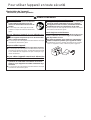
Warning notices
Situations where there is a risk of physical injury to the operator and other people are indicated in this manual and on the product
itself by the following warning notices. Always read and observe them carefully in order to ensure safe operation.
Other indicators
As well as warning notices, this manual uses the following explanatory symbols:
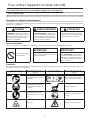
Symbols
In this manual and on the product itself, a series of explanatory symbols is used. Please make sure that you fully understand what
each symbol means.
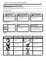
DANGER WARNING CAUTION
This symbol accompanied by the
word "DANGER" calls attentions to
an act or a condition which will lead to
serious personal injury or death of op-
erators and bystanders.
This symbol accompanied by the
word "WARNING" calls attentions to
an act or a condition which can lead to
serious personal injury or death of op-
erators and bystanders.
"CAUTION" indicates a potentially
hazardous situation which, if not
avoided, may result in minor or mod-
erate injury.
Circle and slash sym-
bol means whatever is
shown is prohibited.
NOTE IMPORTANT
This enclosed message provides tips
for use, care and maintenance of the
product.
Framed text featuring the word "IM-
PORTANT" contains important infor-
mation about the use, checking,
maintenance and storage of the prod-
uct described in this manual.
Symbol form/shape Symbol description/applica-
tion
Symbol form/shape Symbol description/applica-
tion
Carefully read the operator's
manual
Keep bystanders away 15 m
Wear eyes, ears and head
protection
Beware of high-temperature
areas
Wear foot protection and
gloves
Keep feet away from blade
Thrown objects Beware of electric shocks

5
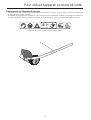
For safe use of your product
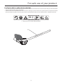
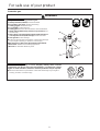
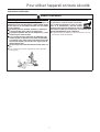
Location in which a safety decal is attached
The safety decal shown below has been attached to the products described in this manual. Ensure that you understand what
the decal means before using your product.
If the decal becomes unreadable due to wear and tear or damage, or peels off and is lost, please purchase a replacement decal
from your dealer and attach it in the location shown in the illustrations below. Ensure that the decal is readable at all times.
1. Safety decal (Part number 890160-25560)

6
For safe use of your product
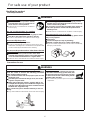
Handling the product
General precautions
Precautions for use
WARNING
Operator's manual
Be careful to read the operator's manual
properly before using your product in or-
der to ensure correct operation.
Failure to do so could lead to an accident or
serious injury.
Do not use the product for anything
other than its intended purpose
You must not use the product for any purpose other
than those described in the operator's manual.
To do so could lead to an accident or serious injury.
Do not modify the product
You must not modify the product.
To do so could lead to an accident or serious injury. Any
malfunction resulting from a modification to the product will
not be covered by the manufacturer's warranty.
Do not use the product unless it has been checked
and maintained
You must not use the product unless it has been
checked and maintained. Always ensure that the prod-
uct is checked and maintained on a regular basis.
Failure to do so could lead to an accident or serious injury.
Loaning or assigning your product
When loaning your product to another party, ensure
that the person borrowing the product receives the op-
erator's manual along with it.
If you assign your product to another party, please en-
close the operator's manual with the product when
handing it over.
Failure to do so could lead to an accident or serious injury.
Being prepared in case of an injury
In the unlikely event of an accident or injury, please ensure
that you are prepared.
First aid kit
Towels and wipes (to stop any bleeding)
Whistle or mobile phone (for calling outside help)
If you are unable to perform first aid or call for outside help,
the injury could worsen.
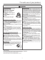
WARNING
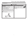
The area within a 15 m radius is a danger zone
The area within a 15 m radius of the product is a danger
zone. Be careful to observe the following precautions
while working with the product.
Do not allow children and other people or pets to enter
the danger zone.
If another person enters the danger zone, turn off the
engine to stop the blade
When approaching the operator, signal to him by, for
example, throwing twigs from outside the danger zone,
and then check that engine has been switched off and
the blade has stopped moving.
Do not allow anyone to hold the material you are cut-
ting.
Any contact with the cutter blade could cause serious injury.
Avoid hot surfaces
During operation, the complete unit, especial-
ly the drive shaft housing, power head, muf-
fler area and gear box may become very hot,
too hot to touch. Avoid contact during and im-
mediately after operation.
You could burn yourself if you touch a high temperature
component.

7
For safe use of your product
WARNING
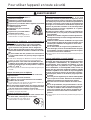
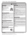
Users of the product
The product should not be used by:
people who are tired
people who have taken alcohol
people who are on medication
people who are pregnant
people who are in poor physical
condition
people who have not read the op-
erator's manual
children
Failure to observe these instruc-
tions could lead to an accident.
Environment of use and operation
Do not use the product in places where there is no sure
foothold, such as on steep slopes or after rainfall, as
such places are slippery and dangerous.
Do not operate the product at night or in dark places
with poor visibility.
Do not work in odd positions or on ladders. Do not over
reach.
A serious injury could result if you fall or slip, or fail to oper-
ate the product correctly.
For your own health and your safe and comfortable
work, operate the machine within the air temperature
range of -5
o
C to 40
o
C.
Failure to observe these instructions could result in damage
to your health.
Turn off the engine when moving around
When moving around in the situations described below,
turn off the engine.
Moving to the place where you are working
Moving to another area while you are working
Leaving the place where you have been working
Failure to observe these precautions could cause burns or
serious injury.
When transporting the product by car, empty the fuel
tank, and secure the product firmly in place to prevent it
from moving around.
Travelling by car with fuel in the tank could lead to a fire.
Keep a firm grip
Hold the front and rear handles with both hands with
thumbs and fingers tightly encircling the handles.
Failure to observe these instructions
could lead to an accident.
Vibration and cold
It is believed that a condition called Raynaud's Phenome-
non which affects the fingers of certain individuals may be
brought about by exposure to vibration and cold. Expo-
sure to vibration and cold may cause tingling and burning,
followed by loss of colour and numbness in the fingers.
The following precautions are strongly recommended be-
cause the minimum exposure which might trigger the ail-
ment is unknown.
Keep your body warm, especially the head and neck,
feet and ankles, and hands and wrists.
Maintain good blood circulation by performing vigorous
arm exercises during frequent work breaks, and also by
not smoking.
Limit the number of hours of operation.
Try to fill each day with jobs where operating the trim-
mer or other hand-held power equipment is not re-
quired.
If you experience discomfort redness and swelling of
the fingers, followed by whitening and loss of feeling,
consult your physician before exposing yourself further
to cold and vibration.
Failure to observe these instructions could result in damage
to your health.
Repetitive stress injuries
It is believed that over-using the muscles and tendons of
the fingers, hands, arms and shoulders may cause sore-
ness, swelling, numbness, weakness and extreme pain to
the areas just mentioned. Certain repetitive hand activities
may put you at a high risk for developing a repetitive
stress injury (RSI).
To reduce the risk of RSI, do the following:
Avoid using your wrist in a bent, extended or twisted
position.
Take periodic breaks to minimize repetition and rest
your hands. Reduce the speed and force in which you
do the repetitive movement.
Do exercises to strengthen hand and arm muscles.
See a doctor if you feel tingling, numbness or pain in
your fingers, hands, wrists or arms. The sooner RSI is
diagnosed, the more likely permanent nerve and muscle
damage can be prevented.
Failure to observe these instructions could result in damage
to your health.
Proper training
Do not permit operation without proper training and protective equipment.
Be thoroughly familiar with the controls and proper use of unit.
Know how to stop the unit and shut off the engine.
Never allow anyone to use the unit without proper instruction.

8
For safe use of your product
Protective gear
WARNING
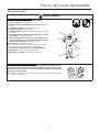
Wear protective gear
Always wear the following protective gear.
a Head protection (helmet): Protects the head
b Ear muffs or ear plugs: Protect the hearing
c Safety goggles: Protect the eyes
d Face shield: Protects the face
e Safety gloves: Protect the hands from cold and vibration
f Work clothes that fit (long sleeves, long trousers): Pro-
tect the body
g Heavy duty, non-slip protective boots (with toecaps) or
non-slip work shoes (with toecaps): Protect the feet
h Shin guards: Protect the legs
Failure to observe these precautions could result in damage
to your sight or hearing, or lead to a serious injury.
When necessary, please use the protective gear below.
Dust mask: Protects the breathing apparatus
Bee net: To deal with attacks by bees
Wear proper clothing.
Do not wear ties, jewellery, or loose, dangling clothing which could be
caught in the unit. Do not wear open toed footwear, or go bare-foot or barel-
egged. In certain situations, total face and head protection may be required.
Failure to observe these precautions could result in damage to your sight or
hearing, or lead to a serious injury.

9
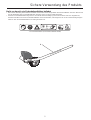
Description
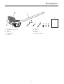
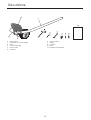
Description
1. Outer tube
2. Cutting attachment shield
3. Blade
4. Gearcase
5. Socket wrench
6. L-wrench
7. Spanner
8. Bolts
9. Wachers
10. Nuts
11. Operator's manual

10
Before you start
Before you start
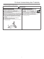
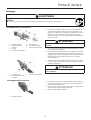
Assembly
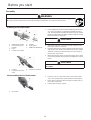
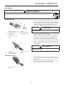
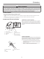
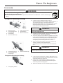
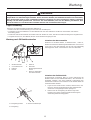
Installing a Tool Attachment
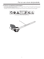
1. Place Multipurpose Engine and the Splitboom Attachment
on a clean, flat surface so that both assemblies fit end to
end. The powerhead assembly should be facing up, and the
Splitboom Attachment should be positioned with the locking
hole in the tube end facing up.
2. Slip off the protective cover from the end of the tool, and
loosen the coupler screw knob.
3. Insert the tube into the coupler, with the tool decal facing up,
until the line of the decal is flush with the end of the coupler.
Twist the tool back and forth until you are sure it snaps in
place by the coupler latch.
4. When the two tube halves are locked together, press down
on the spring-loaded latch protector and tighten the coupler
screw.
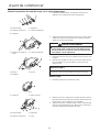
Disassembling the Tool Attachment
1. Place the unit on a clean, flat surface, loosen the coupler
screw. The spring loaded coupler protector should pop up.
2. Press down on the latch with your finger or thumb. This re-
leases the coupler lock.
3. Pull the tube out of the coupler.
WARNING
Read the operator's manual carefully to ensure that you assemble the product correctly.
Using a product that has been incorrectly assembled could lead to an accident or serious injury.
1. Multipurpose engine
2. Latch protector (ex-
tended)
3. Latch
4. Coupler screw knob
5. Coupler
6. Locking hole
7. Splitboom attachment
CAUTION
Keep the open ends of the tubes clean and free of debris.
1. Coupler
2. Latch protector (low-
ered)
3. Coupler screw knob
CAUTION
Make sure there is no gap between the Latch protector and
the coupler.
1. Press latch

11
Before you start
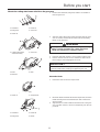
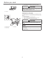
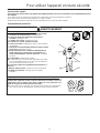
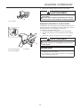
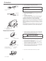
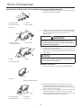
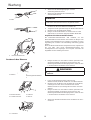
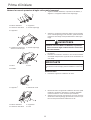
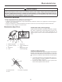
Mount the cutting attachment shield on the gearcase
1. Remove the shaft bolt, bolt guard, holder A and holder B
from the gearcase.
2. Align the cutting attachment shield assembly with the gear-
case as shown, and then fit the shield onto the matching
flange on the gearcase.
3. Install the bolts with washers. Firmly tighten all three bolts.
4. Install a washer and nut on each of the three bolts assem-
bled in Step 3, then firmly tighten each nut.
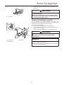
Mount the Blade
1. Install the holder A onto the output shaft.
2. Mount the blade and holder B onto the output shaft, and then
install the bolt guard and shaft bolt (turn bolt counterclock-
wise to install).
3. Align the hole in holder A with the matched hole in the gear-
case, and then use the L-wrench to temporarily lock the out-
put shaft.
1. Shaft bolt 4. Holder A
2. Bolt guard 5. Gearcase
3. Holder B
1. Cutting attachment
shield assembly
2. Gearcase
WARNING
The edger is intended for right-handed operation only.
When correctly assembled, the cutting attachment
shield and shaft must be oriented as shown.
1. Bolts 3. Nuts
2. Washers
IMPORTANT
The three bolts must be firmly tightened against the cutting at-
tachment shield before installing and tightening the nuts.
1. Holder A 2. Output shaft
1. Shaft bolt 3. Holder B
2. Bolt guard 4. Blade

12
Before you start
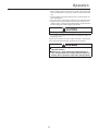
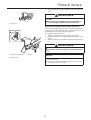
4. Firmly tighten the shaft bolt. Remove the L-wrench.
Adjusting blade cutting depth
The edger's depth of cut is controlled by a combination of opera-
tor height, blade wear, and the positioning of the edger's guide
wheel.
To adjust blade height:
1. Loosen the guide wheel adjusting knob.
2. Raise or lower the guide wheel to the desired setting.
3. Tighten the guide wheel adjusting knob firmly.
1. L-wrench
WARNING
The edger is designed for use with the blade only.
Never operate the edger without the cutting attachment
shield installed and tightly secured.
1. Adjusting knob 3. Numbers
2. Guide wheel
WARNING
Use only shindaiwa replacement blades.
Never adjust the guide wheel while the engine is run-
ning.
NOTE
Guide wheel adjustment is also required to compensate for
blade wear.
The numbers are for reference only; they do not refer to
depth in inches.

13
Operation
Operation
Before edging, make sure the area is soft enough so the blade
does not bog down. If necessary, water the area before edg-
ing.
Remove debris and other obstacles that could be thrown by
the rotating blade.
Plan your work so the blade is always on your right-hand side.
Begin each pass by positioning the unit over the work, and
with the engine running at about half-throttle. Slowly lower the
blade to the ground while applying full throttle.
Do not move the edger into the work so fast that the engine or
blade bogs down.
Regular and frequent use of the edger will make a neater lawn,
and a frequently trimmed edge will be easier to maintain.
CAUTION
Low-speed edging can lead to premature clutch failure.
WARNING
Wear eye protection, long pants, and boots when oper-
ating this machine.
Whenever you strike a hard object with the blade, al-
ways stop the edger and carefully inspect the blade for
damage. Never operate the edger with a damaged blade.

14
Maintenance
Maintenance
Daily Maintenance
50-Hour Maintenance
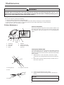
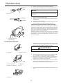
Gearcase lubrication
Remove the shaft bolt, bolt guard, holder A, blade, holder B, and
the output shaft collar. Press new grease into the gearcase until
the old grease has been pushed out. Use only lithium-base
grease.
Lubricate the flexible shaft
Lack of lubrication will cause rapid wear to the flexible shaft and
also to the shaft tube liner, resulting in increased vibration and
greatly decreased service life. Remove and lubricate the flexible
shaft as follows:
1. With the unit on a clean, flat surface, loosen the coupler
screw knob. The spring-loaded Latch protector should pop
up.
2. Press down on the latch with your finger or thumb. This re-
leases the coupler lock.
3. Pull the tool assembly out of the coupler.
4. Pull the flexible shaft and bushing from the shaft tube as-
sembly.
WARNING
Moving parts can amputate fingers or cause severe injuries. Keep hands, clothing and loose objects away from all
openings. Always stop engine, disconnect the spark plug wire, and make sure all moving parts have come to a com-
plete stop before removing obstructions, clearing debris, or servicing unit. Allow unit to cool before performing service.
Wear gloves to protect hands from sharp edges and hot surfaces.
Prior to each work day, perform the following:
Clean any debris or dirt from the cutting attachment.
Lubricate the cutters before use and after refueling. Check the cutters for damage or incorrect adjustment.
Check for loose or missing screws or components. Make sure the cutting attachment is securely fastened.
Make sure nuts, bolts, and screws are tight.
1. Shaft bolt
2. Bolt guard
3. Holder B
4. Blade
5. Holder A
6. Output shaft collar
7. New grease into the
gearcase
1. Latch protector 3. Coupler screw knob
2. Latch
1. Bushing
NOTE
For extended shaft life, the flexible cable should be reversed
end-for-end during the reinstallation process.

15
Maintenance
5. Clean the shaft thoroughly in solvent and dry with a clean
shop towel.
6. Coat the entire length of the shaft with lithium-base grease.
7. Reinstall the flexible shaft.
8. Reinstall the bushing. Push it into the outer tube until it bot-
toms against the collar on the flexible shaft.
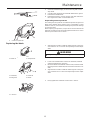
Inspect the gearcase protector
The metal gearcase protector is installed to protect the gearcase
flange from damage when working close to sidewalks or other
abrasive surfaces, and should be routinely inspected for damage
or excessive wear.
When replacing the protector, inspect to be sure that both of the
protector mounting screws are firmly tightened and each screw is
locked in place with a nut as shown.
Replacing the blade
1. Align the hole in holder A with the matching hole in the gear-
case and then use a L-wrench to temporarily lock the output
shaft.
2. Loosen the shaft bolt then remove the shaft bolt, holder B
and the blade from the gearcase.
3. Mount the blade and holder B onto the shaft, and then install
the bolt guard and shaft bolt (turn bolt counterclockwise to in-
stall).
4. Align the hole in holder A with the matching hole in the gear-
case, and then use a L-wrench to temporarily lock the output
shaft.
5. Firmly tighten the shaft bolt. Remove the L-wrench.
1. Gearcase protector
1. Holder A 2. Output shaft
WARNING
Always wear gloves when handling the blade.
1. Shaft bolt, 3. Holder B
2. Bolt guard 4. Blade
1. L-wrench.

16
Maintenance
Checking the blade
Check the blades condition frequently. If the blade's performance
changes suddenly, stop the engine and check the blade for
cracks or other damage. Replace a damaged blade immediately.
WARNING
Never repair a damaged blade by welding, straightening
or by modifying its shape. An altered blade may break
during operation, resulting in serious personal injury.
The Multipurpose Edger Tool is designed for use with a
single, bar-type blade only.
Blades are not interchangeable between shindaiwa edg-
ers and brush cutter models. Operating any machine
with a blade or attachment not approved for that unit
can be hazardous and may cause serious injury.

17
Specifications
Specifications
These specifications are subject to change without notice.
SBA-LE24
Dry weight kg 1.98
Length:
Length
Width
Height
mm
793
171
299
Gear lubricant Lithium-based grease
Gear reduction 1.36:1
Gearcase arbor bolt size 8 mm Left-hand thread

18
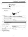
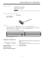
Declaration of conformity
Declaration of conformity
The undersigned manufacturer:
YAMABIKO CORPORATION
7-2 SUEHIROCHO 1-CHOME
OHME; TOKYO 198-8760
JAPAN
This declaration of conformity is issued under the sole responsibility of the manufacturer.
declares that the hereunder specified new unit:
EDGER TOOL
Brand: shindaiwa
Type: SBA-LE24
complies with:
* the requirements of Directive 2006/42/EC (use of harmonized standard EN ISO 11789: 1999)
* the requirements of Directive 2004/108/EC until19th April 2016 (use of harmonized standard EN ISO 14982: 2009)
and 2014/30/EU from 20th April 2016 (use of harmonized standard EN ISO 14982: 2009)
* the requirements of Directive 2000/14/EC
Conformity assessment procedure followed ANNEX V
M243S
Measured sound power level dB(A) 107
Guaranteed sound power level dB(A) 110
Serial Number 35001341 and up
Tokyo, January 1st 2016
YAMABIKO CORPORATION
The authorized representative in Europe who is authorized to
compile the technical file.
Company: Atlantic Bridge Limited
Address: Atlantic House, PO Box 4800, Earley, Reading RG5
4GB, UK
Masayuki Kimura Mr. Philip Wicks
General Manager
Quality Assurance Dept.
La pagina si sta caricando...
La pagina si sta caricando...
La pagina si sta caricando...
La pagina si sta caricando...
La pagina si sta caricando...
La pagina si sta caricando...
La pagina si sta caricando...
La pagina si sta caricando...
La pagina si sta caricando...
La pagina si sta caricando...
La pagina si sta caricando...
La pagina si sta caricando...
La pagina si sta caricando...
La pagina si sta caricando...
La pagina si sta caricando...
La pagina si sta caricando...
La pagina si sta caricando...
La pagina si sta caricando...
La pagina si sta caricando...
La pagina si sta caricando...
La pagina si sta caricando...
La pagina si sta caricando...
La pagina si sta caricando...
La pagina si sta caricando...
La pagina si sta caricando...
La pagina si sta caricando...
La pagina si sta caricando...
La pagina si sta caricando...
La pagina si sta caricando...
La pagina si sta caricando...
La pagina si sta caricando...
La pagina si sta caricando...
La pagina si sta caricando...
La pagina si sta caricando...
La pagina si sta caricando...
La pagina si sta caricando...
La pagina si sta caricando...
La pagina si sta caricando...
La pagina si sta caricando...
La pagina si sta caricando...
La pagina si sta caricando...
La pagina si sta caricando...
La pagina si sta caricando...
La pagina si sta caricando...
La pagina si sta caricando...
La pagina si sta caricando...
La pagina si sta caricando...
La pagina si sta caricando...
La pagina si sta caricando...
La pagina si sta caricando...
La pagina si sta caricando...
La pagina si sta caricando...
La pagina si sta caricando...
La pagina si sta caricando...
La pagina si sta caricando...
La pagina si sta caricando...
La pagina si sta caricando...
La pagina si sta caricando...
La pagina si sta caricando...
La pagina si sta caricando...
La pagina si sta caricando...
La pagina si sta caricando...
La pagina si sta caricando...
La pagina si sta caricando...
-
 1
1
-
 2
2
-
 3
3
-
 4
4
-
 5
5
-
 6
6
-
 7
7
-
 8
8
-
 9
9
-
 10
10
-
 11
11
-
 12
12
-
 13
13
-
 14
14
-
 15
15
-
 16
16
-
 17
17
-
 18
18
-
 19
19
-
 20
20
-
 21
21
-
 22
22
-
 23
23
-
 24
24
-
 25
25
-
 26
26
-
 27
27
-
 28
28
-
 29
29
-
 30
30
-
 31
31
-
 32
32
-
 33
33
-
 34
34
-
 35
35
-
 36
36
-
 37
37
-
 38
38
-
 39
39
-
 40
40
-
 41
41
-
 42
42
-
 43
43
-
 44
44
-
 45
45
-
 46
46
-
 47
47
-
 48
48
-
 49
49
-
 50
50
-
 51
51
-
 52
52
-
 53
53
-
 54
54
-
 55
55
-
 56
56
-
 57
57
-
 58
58
-
 59
59
-
 60
60
-
 61
61
-
 62
62
-
 63
63
-
 64
64
-
 65
65
-
 66
66
-
 67
67
-
 68
68
-
 69
69
-
 70
70
-
 71
71
-
 72
72
-
 73
73
-
 74
74
-
 75
75
-
 76
76
-
 77
77
-
 78
78
-
 79
79
-
 80
80
-
 81
81
-
 82
82
-
 83
83
-
 84
84


in altre lingue
- English: Shindaiwa SBA-LE24 User manual
- français: Shindaiwa SBA-LE24 Manuel utilisateur
- Deutsch: Shindaiwa SBA-LE24 Benutzerhandbuch
Documenti correlati
-
Shindaiwa SBA-AHS2422-LW Manuale utente
-
-
-
-
-
-
-
-
-