
MPR30-IFB User Manual
High performance
True diversity
Receiver
SN: ________________
Rev. 03 (rif. FW v1.5)
Date: 21 March 2014

MPR30-IFB User Manual
Rev. 03

MPR30-IFB User Manual
Rev. 03
BRIEF DESCRIPTION
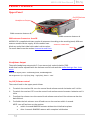
MPR30-IFB is a compact true diversity receiver mono, designed for professional in-ear
monitoring applications. This receiver features a real TRUE DIVERSITY configuration along with
a unique wideband tuning range up to 232 MHz. The audio processing is mono based.
The output audio stage is especially design to have maximum audio peak-dynamic of 200 mW.
MPR30-IFB is designed to be:
o automatic setup functions (i.e. frequencies, scan for best channels),
o remote configuration utilities (thru infrared or micro-USB interface) using
Wisycom MPR30 RX Manager application
o OLED display with intuitive context menu navigation
ency agility up to 232MHz
o MPR30-IFB-N: 470/700 MHz (TV ch 21/49)
o MPR30-IFB-M:566/798 MHz (TV ch 33/61)
extreme RF sensitivity and immunity and superb audio quality
obust design (aluminium
housing) and the possibility to upgrade/enhance units performances.
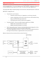
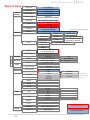
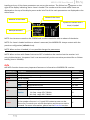
Above a schematic with an overview of main receiver functions.
HP
Amplifier

MPR30-IFB User Manual
Rev. 03
SAFETY INSTRUCTION
Read this safety instruction and the manual first
Follow all instructions and information.
Do not lose this manual.
Do not use this apparatus under the rain or near the water.
Do not install the apparatus near heaters or in hot environments, do not use outside the
operating temperature range.
Do not open the apparatus, only qualified service technician are enabled to operate on it.
The apparatus needs servicing when it is not properly working or is damaged by liquids,
moisture or other objects are fallen in the apparatus.
Use only accessories or replacement parts authorized or specified by the manufacturer.
Clean the apparatus only with dry cloths, do not use liquids.
Report the serial number and the purchasing date in front of the manual. It is needed to
have proper replacement parts or accessories from the manufacturer.
When replacement parts are needed, use only replacement parts authorized from the
manufacturer. Substitution with not authorized parts could result in electric shock,
hazards or fire.
Keep attention on all the labels with warnings or hazards on the apparatus.
The apparatus is intended for professional use; anyway the manufacturer alerts the
user that the headphone output power of the apparatus could exceed the level of 85 dB(A) of
sound pressure level and this could be dangerous for the hearings. Do not use the headphone
with high power level or for long time. Reduce the power or suspend the hearing in case of any
kind of hearing problem.

MPR30-IFB User Manual
Rev. 03
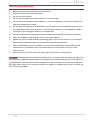
BATTERIES
MPR30-IFB works with standard camera battery:
- 2xIEC-LR6 1.5 size-AA alkaline or NiMh rechargeable
- KLIC 8000 (lithium-ion, rechargeable)
- Ricoh DB-50 (lithium-ion, rechargeable)
- DR9708 Duracell (lithium-ion, rechargeable)
Battery status can be checked on OLED display or looking the status of LED indicator ON.
Lithium-ion battery can be charged through
A. dedicated charger
B. integrated micro-usb-B connector
For B item, the charging status can be checked looking the status of LED indicator ON.
The receiver can be used also during the batteries charging with lithium
rechargeable batteries inside.
The receiver powered thru micro-USB without
batteries doesn't work correctly.
DO NOT operate the device with some new and some old batteries. Always replace
ALL BATTERIES.
Remember to remove the batteries when the device is not in use.

MPR30-IFB User Manual
Rev. 03
PRODUCT OVERVIEW
Upper Panel
SMA antenna Connector A and B
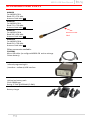
MPR30-IFB is supplied with two couple of antennas. According to the working band, different
antenna models can be supply. All the models have
black cap and a black label with code in white colour.
For more details see the section Accessories and Parts
Headphone Output
The audio headphone output with 3.5 mm stereo jack socket lockable (TRS).
Audio level can be adjusted with the Volume control knob and the Audio settings> Pwr. Limit
menu.
Maximum output power: 2x150mW @ 32Ω, 2x200mW@16Ω
Pin Assignment: Tip = left (hot), Ring = right (hot), Sleeve = Gnd
On/Off/Volume control
The control knob in the upper panel allows:
To switch the receiver ON: turn the control knob volume control clockwise until it clicks
To switch the receiver OFF: turn the control knob volume control counter clockwise until it
clicks
To adjust the volume: turn the control knob volume control until the volume set has the
desired level.
To disable the lock volume: turn off and turn on the receiver within 1 second.
NOTE: turn off and turn on the receiver
within 1 secondMPR30 restarts without the initialization phase
after 1 second MPR30 restarts with complete initialization
SMA connector Antenna B
SMA connector Antenna A
On/Off/Volume
control
Headphone Output
Antenna Code label

MPR30-IFB User Manual
Rev. 03
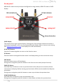
Front panel
MPR30-IFB allows an easy and quick configuration using buttons, RGB
display.
OLED Display
The receiver has a high contrast display. Pushing one of the 4 buttons while the receiver is
active (but the display is off), turn on automatically the display. After a time-out user setting
(see Display>Off timeout menu) the display turns off automatically.
SEL & EXIT Buttons
Push the 2 buttons together to enter on the function menu
SEL Button
keep pushing to save the chosen setup
EXIT Button
Push this button to turn off the display.
During menu navigation push this button to exit from current menu (escape function).
SYNC/UP Button
Push and keep this button to start a synchronisation with a Wisycom transmitter (follow
instructions on display). Before starting synchronization IRDA must be enabled on Wisycom
transmitter.
During menu navigation push this button to move -up and select the previous item.
SCAN/DOWN Button
Push and keep this button to start the automatic scan.
During menu navigation push this button to move-down and select the previous item
SCAN/DOWN
Button
SYNC/UP
MENU/EXIT
Button
MENU/SELECT
Button
ON Led Indicator
RF Led Indicator
Infrared Interface
(IR)

MPR30-IFB User Manual
Rev. 03
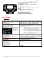
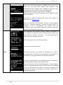
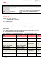
ON Led Indicators (Firmware rel. v1.5)
COLOR
WHEN
MEANING
Red
During the power up phase
The receiver is not ready to use
After the power up phase
The PLL is not locked on the select frequency, wait
for lock ( about 1second or less). If after few
seconds the ON led remains red, contact Wisycom
Fixed Green
After the power up phase
The receiver is locked on the select frequency, the
batteries charge is good (>25% lifetime)
During a battery charge
Charge complete
Slow Blinking
Green
After the power up phase
The receiver is locked on the select frequency, the
batteries charge is low (<25% lifetime)
During a battery charge
T
reached)
Fast Blinking
Green
After the power up phase
The receiver is locked on the select frequency, the
batteries charge is very low (<12% lifetime)
Green/Red
blinking
During a scan operation
The device is doing a scan of the frequencies
Blue
During a battery charge
The batteries are charging (<90% of complete
charge)
Pink
In the boot mode
The device is in the boot mode
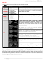
RF Led Indicators (Firmware rel. v1.5)
COLOR
RF level
TONE SQUELCH (19KHz)
AUDIO
Why is audio disable?
Red
RF>Squelch
Enable but not detected
Disable
Tone squelch not detected
RF<Squelch
Enable but not detected
Disable
Tone squelch not detected
RF<Squelch
Disable
Disable
RF<Squelch
Green
RF>Squelch
Enable and detected
Enable
RF<Squelch
Enable and detected
Disable
RF<Squelch
RF>Squelch
Disable
Enable
Orange
The device is in the boot mode
* to put the MPR30-IFB in boot mode: power on the device push and keep both UP and DOWN buttons for few
seconds (until the led indicators light up, then release the buttons)

MPR30-IFB User Manual
Rev. 03
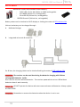
PUTTING THE DIVERSITY RECEIVER INTO OPERATION
Insert the batteries
Connect the headphones
Connect the 2 antennas on the SMA connectors
Turn the knob control clockwise until it clicks and verify on the display the Antenna
model to use (if the connected antennas on the receiver is different from the
antenna model indicate on the display, power off the receiver and replace them with
the proper model of antennas)
after the power up phase, the Status display is showed on the OLED display
verify the setting and eventually adjust the settings using the Operating Menu
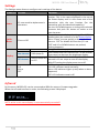
Status display
- Receiver Name (ex. MPR30-IFB RX)
- Group (ex. Gr:00) and Channel (ex. Ch:01)
- Frequency (ex. Fr:567.000 MHz)
- Squelch (ex. Sq:9dBuV)
- Jack (ex. Stereo)
A. RF Level Antenna A and B (range 5 ÷ 70 dBµV)
An orizzontal sign in a central row shows the setted Squelch level
B. deviation level (range of 54dB, bar with 3dB steps; upper level= 0dB, under level =-54dB)
the upper symbol:
indicates presence of audio output
indicates absence of audio output (RF level < Squelch)
indicate absence of audio output (no pilot Squelch detected)
NOTE: in case of absence of pilot squelch and RF level < Squelch, the symbol will be
display
C. batteries level for MPR30-IFB receiver
S
A
B
C
CSquelch level
P

MPR30-IFB User Manual
Rev. 03
DISPLAY MENU
MENU
Audio
Settings
Head Jack Stereo/Mono
Equalizer
Low (-12÷+12)
Hi (-12÷+12)
Vol. boost -12÷+12dB
Output load /
Pwr limit OFF/100mW/50mW/30mW
Edit RX
Gr-Ch
GR (0÷39)
CH (0÷59)
Frequency
N: 470.000÷700.000
M: 566.000÷798.000
Squelch OFF*-0/3/6/9/12/15/18/21/24//28/32/36/40/46 dBµV
Scan
Scan now
Channel GR 00 - 39
Groups more groups (max 10)
Freq
freq. Min/ freq. Max/
step (100 or 200 kHz)
Squelch scan
Scan BTN Channel/Groups/Freq
View last
Deploy
Settings
Name
12 characters
ex. RECEIVER-123
Quick Menu Clone / Off
Display
Contrast 0÷5
Low timeout (sec) 5÷60 steps 5
Off timeout (sec) 10÷120 steps 10 - OFF
LED Full/Alarm/OFF
Infrared
Sync
Advanced
Lock volume Yes/No
Pilot Squelch Yes/No
Clone
Add 00÷23
Load default/0/...
Delete 00÷23
Delete all
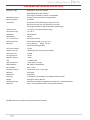
Info
Model MPR30-IFB
Range 470÷700
Serial Q152657
FW
Version v1.5
BL v1.4d
App v1.54d
HW
Version 2
Option N
Battery 3.71 Volt
Errors 0
Preset
Restore 1/2/3/4/5/6/Factory
Save 1/2/3/4/5/6
*Only using lithium battery
Preset parameters
Clone parameters
It appears if
exist at least
1 clone

MPR30-IFB User Manual
Rev. 03
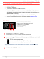
From Status Display push SEL and EXIT together to
enter on the Main menu
Use UP/DOWN to navigate on all available menus
Push SEL to select a menu item
Use UP/DOWN to move on the different parameters of
the menu
Push SEL to modify the parameter menu
Use UP/DOWN to change the parameter value
Keep push SEL to save changing
Push EXIT to return on the Main Menu
Push EXIT to return on the Status display
Audio settings
The Audio settings menu allows to configure the audio output.
PARAMETER
SETTING
MEANING
Head Jack
Stereo/Mono
Depending on the type of headphones used, the
headphone output can be set to Stereo or Mono
Equalizer
Low and High
frequencies
-12dB/+12dB
1dB steps
This menu allows to of adjusting the gain of low and
high frequency components (bass and treble) within
the audio signal.
1. Push UP/DOWN button to increase/decrease
the gain of the Low frequencies (50Hz)
2. Push SEL button to shift on High frequencies,
3. Push UP/DOWN button to increase/decrease
the gain of the High frequencies (10kHz)
4. Keep push SEL button to SAVE
Vol. boost
-12/-6/0/3/6/9/12dB
This menu allows to increase or decrease the volume
of the output headphones, selectable from -12 dB to
12 dB. Set the appropriate volume boost and then
adjust the volume with the control knob.
Output load
Set the Output load according to the impendence of
the headphones connected
Pwr limit
OFF (only using lithium
battery)
100mW
50mW
30mW
This menu allows to limit the power output. If set to
OFF(only lithium battery), there is no power limit
control. If set to OFF using alkaline or NiMH batteries,
the receiver set automatically the max value permitted
(100mW)

MPR30-IFB User Manual
Rev. 03
Edit RX
The Edit RX menu allows to configure the radio frequency settings.
PARAMETER
SETTING
MEANING
Gr-Ch
0÷39 groups
0÷59 channels
Select current group and channel. Group name and
channel frequency are displayed on the right.
Frequency
470÷700 MHz
for MPR30-IFB-N
566÷798 MHz
for MPR30-IFB-M
If the specific group/channel is not locked, the frequency
can be edited in this menu.
Squelch
OFF or
0/3/6/9/12/
15/18/21/
24/28/32/
36/40/46dBuV
This menu allows to disable the RF squelch or to setup the
desired squelch level in dBuV (note 0 dBuV is equal to -
107 dBm).
Scan
It allows making three types of scan over a desired
channel, group or frequency. MPR30-IFB manages up to
2400 custom frequencies organized in 40 groups of 60
channels each. This extreme flexibility makes the scan
function very flexible.
This function can be called also using the dedicated
DOWN&SEL buttons pushed together.
Squelch scan indicates the threshold below which a
channel is considered as free or almost free.
Scan BTN is the parameter to set the rapid function
called pressing DOWN&SEL buttons together.
View last allows to see the result of the last scan
operation.
Deploy allows to send to a MTK952 the last scan.
of the
last scan and choose the frequency to tune.
(*)As per Wisycom standard, group 00 and group 01 or 09 are special; respectively the “center
frequency” (474,482/ MHz) and the intergap frequency (i.e. 470/478/486/ MHz). A scan on group
00 will reveal in few seconds the overall DVB-T occupation on the area, while a scan on group 01 will
give possible working frequency, usable also in presence of strong DVB-T signal (sort to speak working
in the band-guard of 2 digital television channels).

MPR30-IFB User Manual
Rev. 03
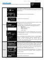
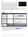
“Scan now” menu
The following table lists the three types of scans that can be performed
Channel
Once started a Channel scan operation the receiver asks for
group to be used*. Press and hold the SEL button to select the
group to scan.
Then it prompts to turn off all transmitters.
So press SEL to start the scan!
After few seconds, scan results are displayed sorted by level,
making easier to pick up the best one.
The dotted line in the graph indicate the squelch threshold.
Under the graph are reported the following parameters:
- Ch: Channel
- Rank: Ranking position
- Freq: Frequency
- Lev: RF level
Pushing simultaneously UP and DOWN button, the results can
be also displayed on a chart in ascending order according to
the number of the channel.
After the selection of the desired channel, a screen appears
with the selected frequency, channel and group and it is
possible to Set or Synchronize the receiver with the
transmitter. We recommend setting the frequency and then
synchronize it with the transmitter.
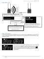
Groups
If the scan is done on Groups, you can choose a maximum of
10 groups from among the 40 groups shown in the table
(Press the SEL button to select and press it again to deselect).
In the upper left shows the number of the selected group and
the number of selected groups, while in the upper right corner
there is the item "START" to start the scan.
To select START, go to the box 39 and press the "UP" button or
go to the box 0 and press the "DOWN" button, so press SEL to
run the scansion.
Then it prompts to turn off all transmitters.
So press SEL to start the scan!

MPR30-IFB User Manual
Rev. 03
After few seconds, scan results are displayed on a histogram.
Each column of the histogram is divided into two parts by a
black line. The lower part indicates the number of free
channels (RF level < Squelch level - 6dBµV) in the group, while
the upper one the number of channels almost free
(Squelch level < RF level < Squelch level - 6dBµV).
We recommend to choose the group with the highest number
of free channels.
Press SEL to select the desiderate group and choose the
channel as in Channel scan
After the selection of the desired channel, a screen appears
with the selected frequency, channel and group and it is
possible to Set or Synchronize the receiver with the
transmitter. We recommend setting the frequency and then
synchronize it with the transmitter.
Freq
The Frequency scan allows to select a range of frequency to
scan, between a maximum and a minimum value and the step
with which to perform the scans. Press and hold the SEL
button to select the group to scan.
Then it prompts to turn off all transmitters.
So press SEL to start the scan!
After few seconds, scan results are displayed on a chart in
ascending order according to the frequency (step 1MHz). The
dotted line in the graph indicate the squelch threshold.
s possible to
zoom the graph to show all the steps of scan
After the selection of the desired frequency, a screen appears
with the selected frequency and the RF level and it is possible
to Set or Synchronize the receiver with the transmitter. We
recommend setting the frequency and then synchronize it
with the transmitter.

MPR30-IFB User Manual
Rev. 03
Settings
The Settings menu allows to configure main settings of the device.
PARAMETER
SETTING
MEANING
Name
12 case-sensitive alphanumeric
characters
The name menu allows to change the name of the
receiver. This is the name displayed in the top of
the Status display and it is the name sent to the
transmitter with the sync function (for the
transmitter with this advanced capability).
Use the UP/DOWN buttons to change the selected
character and push SEL button to switch to the
next character.
Quick
Menu
Clone or Off
The quick menu is displayed pushing UP or DOWN
buttons when the receiver is on the Status display.
m
nothing happens).
Display
Contrast
0÷5
Change contrast display from 0 (min) to 5 (max).
Low timeout
5÷60 (steps 5)
Low timeout sets the timeout from 5 to 60 seconds
(5sec steps) to decrease the brightness display.
Off timeout
10÷120 (steps 10)
or OFF
Off timeout sets the timeout from 10 to 120
seconds in 10 sec. steps to turn off the display.
With OFF setting the display never turns off.
LED
Full
Alarm
OFF
3 LED setting are available:
Full: LED indicators works normally;
Alarm: LED indicators lights up only when an alarm
happened;
OFF: LED indicators remain off.
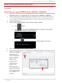
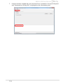
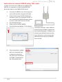
Infrared
By this menu, MPR30-IFB can be connected to IRDA for setup or firmware upgrades.
When the Infrared interface is active, the following screen is displayed.
NOTE: while in this menu display is not automatically turned off.

MPR30-IFB User Manual
Rev. 03
Sync
The SYNC function is useful to tune a transmitter on the same
frequency of the receiver via the IR interface. Before starting the
sync function tune the receiver on desired channel, manually or
using the SCAN utility. After this, enable the IR interface on the
transmitter. Now press UP&EXIT buttons together or enter in the
Sync menu to start the SYNC function. Keep the IR window of the
transmitter in front of the IR window of the receiver and, as soon as the connection is done, the
receiver will send to the transmitter all the information needed.
If the operation is not possible, (i.e. the frequency range of the transmitter is not compatible with
the frequency of the receiver), the display will show an error message.
If the transmitter function is completed it will
show the same name of the synchronized receiver.
Advanced
The Advanced menu allows to manage advanced settings.
PARAMETER
SETTING
MEANING
Lock volume
Yes / No
display an open lock is displayed on the Status
Display -Low timeout
becomes closed and the lock volume is enabled.
To enable the volume setting it is necessary turn
the volume knob below the previous setting or
Pilot Squelch
Yes / No
When the Pilot tone is enabled, the audio output is
muted unless the correct carrier is detected
(19kHz).
When the Pilot tone is disable, the audio output is
muted if RF level < Squelch level.
For the presence/absence of audio output, check
the upper symbol in the status display.
Clone *
Add
00÷23
To add a clone
Load
Default/00÷23
To load a clone *
Delete
00÷23
To delete a clone *
Delete all
To delete all the clones *
* A clone is a partial configuration of the MPR30-IFB which can be copied from a receiver to another
using the IRDA interface. It consists of the same parameters of pre-set configuration for less than
display, quick menu and headphones parameters (see the Operating menu for more details).
From firmware version v1.3 the MPR30-IFB is able to manage up to 24 clones (from 00 to 23). The
menus of the clone management allow to add/load and delete a clone.
* It appears if exist at least a1 clone

MPR30-IFB User Manual
Rev. 03
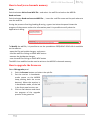
How to add a clone
Out mode
Balance
Equalizer
Vol boost
Pilot tone
Gr-Ch
Squelch
RX Name
How to load a clone
Use Clone>Load menu or UP/DOWN button (if the quick menu is configured to clone) to load a
clone. Afterwards push the arrows to change clone, SEL to activeted the clone and EXIT to exit
without changing.
Ex.
The configuration saved before the loading of the clone is saved on
the clone default, theref
allows to return with the previous settings. The following
arrows displayed near the clone number indicates the currently
clone loaded.
Clone name
Enable the IRDA interface on the RX from
which take the configuration (Infrared menu)
Enter in the Add menu and select the
wanted clone number. Then push SEL
to start the IRDA communication.
Put the receivers face
to face
At the end of the process the name
of the clone will be identify with the
name of the receiver.

MPR30-IFB User Manual
Rev. 03
Loading a clone, all the clone parameters are set on the receiver. The follow icon appears on the
right of the display indicating that a clone is loaded. The number and the name of the clone are
displayed on the top of the display menu and a brief list of the main parameters are displayed on the
status menu.
NOTE: the clones are saved on the EPROM and remains saved also after a reboot of the device.
NOTE: If a clone is loaded and then a reboot is executed, the MPR30-IFB always restarts with the
previous configuration (default clone).
NOTE: When a clone is loaded, it's not possible change the parameters
NOTE: When a clone with Power limit set to OFF is loaded
using Lithium battery, the power limit is set automatically to the max value permitted for no lithium
battery (that is 100mW).
Info
the INFO function shows many important features or information of MPR30-IFB receiver:
PARAMETER
MEANING
example
Model
Wisycom receiver model
MPR30-IFB
Range
Frequencies range of working
470-700
Serial
Serial number
Q152657
FW
Version *
Firmware version
V1.5
BL
Bootloader version
V1.4d
App
Application version
V1.54d
HW
Version
Hardware version
2
Option
MPR30-IFB Options
N= freq. range
470 ÷ 700 MHz
,
M= freq. range
566 ÷ 798 MHz
N
Battery
Batteries voltage
3.71 Volt
Errors
Number of errors.
If the number of errors is > 0 push SEL button to enter on the
Errors list. For each error a brief description and the error code is
showed. For more information, please see the Error List section.
4
* The Firmware Version recaps BL (Bootloader Version) and App (Application version).
Name of the clone
symbol to indicate that a
clone is loaded
is loaded
Number of the clone
Main parameters

MPR30-IFB User Manual
Rev. 03
Preset
This menu allows to load/save 6 user presets or load the Factory configuration.
PARAMETER
SETTING
MEANING
Restore
1/2/3/4/5/6/Factory
Select the Restore submenu and chose the presets
to load: user presets or Factory preset. Push and
keep SEL button to load the preset.
Save
1/2/3/4/5/6
Select the Save submenu and chose the user presets
to save. Push and keep SEL button to save the
preset
ERROR LIST
When an error occurs, the receiver
A. shows a message on the display
and for some error types
B. increases the errors counter in the info menu
C. inserts the error type and code on the error list in the info menu
When the error is solved, the message on the display disappear, but the error information
(code and description) are available on the error list in the Info menu (only for some error, see
the below table).
NOTE
1
: When the receiver is reset the error information (code and error type on the list) are
lost, with the exception of errors codes 87/88/89/8A.
NOTE
2
: To reset the error counter and the errors list, it is necessary to contact Wisycom.
Errors
Message on display
(A)
Error type
(C)
Code
(C)
HW init failed
HW init failed
Battery Low
Battery Low
Battery charge failed
Battery charge failed
I2C communication error
I2C communication error
I2C access failed
04
Device ID copy1 invalid
Memory recovered
Device ID copy1 invalid
Memory recovered
Device ID copy 1
87
Device ID copy2 invalid
Memory recovered
Device ID copy2 invalid
Memory recovered
Device ID copy 2
88
RF copy1 invalid
Memory recovered
RF copy1 invalid
Memory recovered
RF mem copy 1
89
RF copy2 invalid
Memory recovered
RF copy2 invalid
Memory recovered
RF mem copy 2
8A
PLL unlocked
-
PLL unlocked
84
CH mem header
-
CH mem header
85
Param mem header
-
Param mem header
86

MPR30-IFB User Manual
Rev. 03
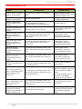
TROUBLESHOOTING
Problem
Possible cause
Possible solution
HW init failedmessage
appears on the display
Error during the hardware initialization
phase
-reset the receiver, if the
problem persists send to repair
at Wisycom Repair Centre
Battery Lowmessage
appears on the display
Low level on the battery
- change batteries or
- recharge the batteries
Battery charge failed
message appears on the
display
Error during batteries charger
(damage batteries or wrong batteries)
- change batteries
I2C communication error
message appears on the
display
Communication error on bus I2C
- send to repair at Wisycom
Repair Centre
Device ID copy1 invalid
Memory recovered
message appears on the
display
Error during the initialization phase. The
CRC-16 check of device data (copy 1)
detects error.
- nothing (the receiver
automatically replace the
corrupt copy1 with copy2)
Device ID copy2 invalid
Memory recovered
message appears on the
display
Error during the initialization phase. The
CRC-16 check of device data (copy 2)
detects error.
- nothing (the receiver
automatically replace the
corrupt copy2 with copy1)
RF copy1 invalid
Memory recovered
message appears on the
display
Error during the initialization phase. The
CRC-16 check of RF data (copy 1) detects
error.
- nothing (the receiver
automatically replace the
corrupt copy1 with copy2)
RF copy2 invalid
Memory recovered
message appears on the
display
Error during the initialization phase. The
CRC-16 check of RF data (copy 2) detects
error.
- nothing (the receiver
automatically replace the
corrupt copy2 with copy1)
The Serial Number of the
receiver in the Info menu
is UNCAL
Error during the initialization phase. The
CRC-16 check of device data (copy 1 and
copy 2) detects error.
- send to repair at Wisycom
Repair Centre
The errors 87 (Device ID
copy 1 ) and 88 (Device ID
copy 2) appear in the
errors list
Error during the initialization phase. The
CRC-16 check of device data (copy 1 and
copy 2) detects error.
- If the Serial Number in the
Info menu is UNCAL, then send
to repair at Wisycom Repair
Centre
- If the Serial Number in the
Info menu is not UNCAL,
continue to use the receiver
The errors 89 (RF mem.
copy 1 ) and 8A (RF meme.
copy 2) appear in the
errors list
Error during the initialization phase. The
CRC-16 check of RF data (copy 1 and copy
2) detects error.
- contact Wisycom for more
information
The receiver is not able to
tuned on the selected
frequency and the ON led
indicator remains red
Error during frequency tuning
- try to change the frequency, if
the problem persists send to
repair at Wisycom Repair
Centre
La pagina si sta caricando...
La pagina si sta caricando...
La pagina si sta caricando...
La pagina si sta caricando...
La pagina si sta caricando...
La pagina si sta caricando...
La pagina si sta caricando...
La pagina si sta caricando...
La pagina si sta caricando...
La pagina si sta caricando...
La pagina si sta caricando...
La pagina si sta caricando...
-
 1
1
-
 2
2
-
 3
3
-
 4
4
-
 5
5
-
 6
6
-
 7
7
-
 8
8
-
 9
9
-
 10
10
-
 11
11
-
 12
12
-
 13
13
-
 14
14
-
 15
15
-
 16
16
-
 17
17
-
 18
18
-
 19
19
-
 20
20
-
 21
21
-
 22
22
-
 23
23
-
 24
24
-
 25
25
-
 26
26
-
 27
27
-
 28
28
-
 29
29
-
 30
30
-
 31
31
-
 32
32


in altre lingue
- English: WisyCom MPR30-IFB User manual
Documenti correlati
-
WisyCom MPR30-IEM Manuale utente
-
-
-
-
-
-
-
-
-