Sony VPH-G70Q Operating Instructions Manual
- Categoria
- Proiettori di dati
- Tipo
- Operating Instructions Manual
Questo manuale è adatto anche per

©1999 by Sony Corporation
3-866-495-11 (1)
VPH-G70Q
VPH-G70QM
VPH-G70QMG
Operating Instructions
Multiscan Projector
• The PDF data of the Operating Instructions and Installation Manual for Dealers (French, German,
Spanish and Italian) are contained in the supplied CD-ROM. If you need a manual other than the
English one, please read the data of the CD-ROM or print them out with a printer.
• When you use the CD-ROM, please read its “ReadMe” section, which introduces how to use the
CD-ROM.
• Les données PDF du mode d’emploi et du manuel d’installation destiné aux revendeurs (français,
allemand, espagnol et italien) se trouvent sur le CD-ROM fourni. Si vous avez besoin d’une autre
version du manuel que la version anglaise, consultez les données sur le CD-ROM ou imprimez-
les au moyen d’une imprimante.
• Avant d’utiliser le CD-ROM, veuillez lire la section “LisezMoi” qui vous explique comment exploiter
le CD-ROM.
• El CD-ROM suministrado contiene los datos PDF de los manuales de instrucciones y de
instalación para proveedores (español, francés, alemán e italiano). Si necesita un manual que no
sea el inglés, lea los datos del CD-ROM o imprímalos con una impresora.
• Cuando utilice el CD-ROM, lea su sección “Léame”, en la que se describe cómo emplear dicho
CD-ROM.
• Die Bedienungsanleitung und das Installationshandbuch für Händler (Französisch, Deutsch,
Spanisch und Italienisch) befinden sich im PDF-Format auf der mitgelieferten CD-ROM. Wenn Sie
nicht mit dem englischen Handbuch arbeiten möchten, lesen Sie bitte das Handbuch in der
gewünschten Sprache auf der CD-ROM, oder drucken Sie es aus.
• Wie Sie die CD-ROM verwenden, ist unter “ReadMe” auf der CD-ROM beschrieben.
• Le istruzioni per l’uso e il manuale d’uso per i rivenditori in formato PDF in lingua francese,
tedesca, spagnola e italiana sono contenuti nel CD-ROM in dotazione. Se occorre una copia dei
manuali non in lingua inglese, è possibile visualizzare i manuali del CD-ROM a video oppure
stamparli.
• Se si utilizza il CD-ROM, leggere la sezione “Leggimi” che spiega come utilizzare il CD-ROM.

2
WARNING
To prevent fire or shock hazard, do not
expose the unit to rain or moisture.
To avoid electrical shock, do not open the
cabinet. Refer servicing to qualified
personnel only.
For the customers in the USA
Note
This equipment has been tested and found to comply with
the limits for a Class A digital device, pursuant to Part 15 of
the FCC Rules. These limits are designed to provide
reasonable protection against harmful interference when
the equipment is operated in a commercial environment.
This equipment generates, uses, and can radiate radio
frequency energy and, if not installed and used in
accordance with the instruction manual, may cause harmful
interference to radio communications. Operation of this
equipment in a residential area is likely to cause harmful
interference in which case the user will be required to
correct the interference at his own expense.
Warning
You are cautioned that any changes or modifications not
expressly approved in this manual could void your authority
to operate this equipment.
This symbol is intended to alert the
user to the presence of uninsulated
“dangerous voltage” within the
product’s enclosure that may be of
sufficient magnitude to constitute a risk
of electric shock to persons.
This symbol is intended to alert the
user to the presence of important
operating and maintenance (servicing)
instructions in the literature
accompanying the appliance.
For the customers in Canada
This Class A digital apparatus meets all requirements of the
Canadian Interference-Causing Equipment Regulations.
For the customers in the United Kingdom
WARNING
THIS APPARATUS MUST BE EARTHED
IMPORTANT
This wires in this mains lead are coloured in accordance with
the following code:
Green-and-Yellow: Earth
Blue: Neutral
Brown: Live
As the colours of the wires in the mains lead of this
apparatus may not correspond with the coloured markings
identifying the terminals in your plug proceed as follows:
The wire which is coloured green-and-yellow must be
connected to the terminal in the plug which is marked by the
letter E or by the safety earth symbol Y or coloured green or
green-and-yellow.
The wire which is coloured blue must be connected to the
terminal which is marked with the letter N or coloured black.
The wire which is coloured brown must be connected to the
terminal which is marked with the letter L or coloured red.
Voor de klanten in Nederland
• Dit apparaat bevat een Li-ion batterij voor memory back-
up.
• De batterij voor memory back-up van het geheugen is
bevestigd op IC308 van plaat YB.
• Raadpleeg uw leverancier over de verwijdering van de
batterij op het moment dat u het apparaat bij einde
levensduur afdankt.
• Gooi de batterij niet weg, maar lever hem in als KCA.
• Bij dit product zijn batterijen geleverd.
Wanneer deze leeg zijn, moet u ze niet
weggooien maar inleveren als KCA.
The socket-outlet should be installed near the equipment
and be easily accessible.

3
La toma mural debe estar instalada cerca del equipo y
debe accederse a ésta con facilidad.
AVERTISSEMENT
ACHTUNG
Pour les utilisateurs au Canada
Cet appareil numérique de la classe A respecte toutes les
exigences du Réglement sur le matériel brouilleur du
Canada.
La prise doit être près de l’appareil et facile d’accès.
Für Kunden in Deutschland
Dieses Produkt kann im kommerziellen und in begrenztem
Maße auch im industriellen Bereich eingesetzt werden. Dies
ist eine Einrichtung, welche die Funk-Entstörung nach
Klasse B besitzt.
Die Steckdose muß nahe bei diesem Gerät angebracht
und leicht zugänglich sein.
Afin d’éviter tout risque d’incendie et d’électrocution, ne
pas exposer l’appareil à la pluie ou à l’humidité.
Pour éviter tout risque de décharge électrique, ne pas
ouvrir le boîtier. Confiez l’entretien uniquement à un
personnel qualifié.
Um Feuergefahr und die Gefahr eines eiektrischen
Schlages zu vermeiden, darf das Gerät weder Regen
noch Feuchtigkeit ausgesetzt werden.
Im Geräteinneren befinden sich Teile, die unter
gefährlich hoher Spannung stehen. Das Gehäuse darf
nicht geöffnet werden. Überlassen Sie die Wartung nur
geschultem Fachpersonal.
Para evitar riesgos de incendio o electrocución, no
exponga la unidad a la lluvia ni a la humedad.
Para evitar recibir descargas eléctricas, no abra el
aparato. Contrate exclusivamente los servicios de
personal cualificado.
Per evitare il pericolo di incendi o scosse elettriche, non
esporre l’apparecchio alla pioggia o all’umidità e non
aprirlo.
Per eventuali riparazioni, rivolgersi esclusivamente a
personale qualificato.
ADVERTENCIA
AVVERTENZA
La presa di corrente deve essere situata vicino
all’apparecchio e deve essere facilmente accessibile.

4

5
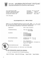
Die geforderte Stückprüfung hat ergeben, daß die gemessene Ortsdosis-Leistung unter dem
im Prüfungsschein Nr. 6.22-S 1227 der PTB genannten Wert von 0,2 µSv/h liegt.

6
The instructions in this manual are for models VPH-G70Q, VPH-G70QM and
VPH-G70QMG. Before you start reading, check your model number. The VPH-
G70Q/QM are the models used for illustration purposes. The S VIDEO IN/OUT
connectors and VIDEO IN/OUT connectors on the rear panel are not supplied
with the VPH-G70QMG. Any differences in operation are clearly indicated in the
text.

7
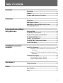
Table of Contents
Overview
Projecting
Precautions.........................................................................8
Features ............................................................................10
Location and Function of Controls ................................11
Projecting..........................................................................19
Adjusting the Picture .......................................................21
Adjusting the Size and Shift of the Picture....................22
Centering Adjustment......................................................24
Adjustments and settings
using the menu
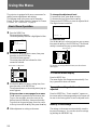
Using the Menu ................................................................26
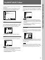
The INPUT SELECT Menu ...............................................27
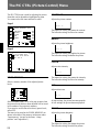
The PIC CTRL (Picture Control) Menu ...........................28
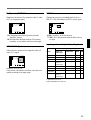
The INPUT SETTING Menu ..............................................30
The SET SETTING Menu..................................................33
The INPUT INFO (Information) Menu..............................36
The OPTION Menu............................................................37
Installation/connection
examples
Installation Examples ......................................................38
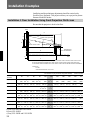
Installation 1 Floor Installation Using Front Projection
Flat Screen.................................................................. 38
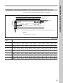
Installation 2 Ceiling Installation Using Front Projection
Flat Screen.................................................................. 39
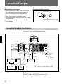
Connection Examples......................................................40
Connecting Directly to the Projector............................... 40
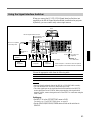
Using the Signal Interface Switcher................................ 41
Other
Maintenance
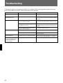
Troubleshooting...............................................................42
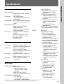
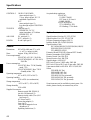
Specifications...................................................................43
Index..................................................................................46

8
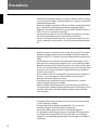
On safety
•Check that the operating voltage of your unit is identical with the voltage
of your local power supply. If voltage adaptation is required, consult with
qualified Sony personnel.
•Should any liquid or solid object fall into the cabinet, unplug the unit and
have it checked by qualified personnel before operating it further.
•Unplug the unit from the wall outlet or set the MAIN POWER switch to
OFF if it is not to be used for several days.
•To disconnect the cord, pull it out by the plug. Never pull the cord itself.
•The wall outlet should be near the unit and easily accessible.
•The unit is not disconnected from the AC power source (mains) as long
as it is connected to the wall outlet, even if the unit itself has been turned
off.
On installation
•When the projector is mounted on the ceiling, the Sony PSS-70 Projector
Suspension Support must be used for installation. Read the installation
manual of the PSS-70 carefully, since the ceiling should be reinforced for
safety.
•Allow adequate air circulation to prevent internal heat build-up. Do not
place the unit on surfaces (rugs, blankets, etc.) or near materials (curtains,
draperies) that may block the ventilation holes. Leave space of more than
30 cm (12 inches) between the wall and the projector. Be aware that room
heat rises to the ceiling; check that the temperature near the installation
location is not excessive.
•Do not install the unit in a location near heat sources such as radiators or
air ducts, or in a place subject to direct sunlight, excessive dust or
humidity, mechanical vibration or shock.
•To avoid moisture condensation, do not install the unit in a location
where the temperature may rise rapidly.
•Fans are installed inside the projector to prevent internal heat build-up.
The fans produce a humming noise when the power is switched on, which
is normal. Should the noise sound abnormal, please consult qualified
Sony personnel.
On illumination
•To obtain the best picture, the front of the screen should not be exposed
to direct lighting or sunlight.
•Ceiling-mounted spot lighting is recommended. Use a cover over
fluorescent lamps to avoid lowering the contrast ratio.
•Cover any windows that face the screen with opaque draperies.
•It is desirable to install the projector in a room where floor and walls are
not of light-reflecting material. If the floor and walls are of reflecting
material, it is recommended that the carpet and wall paper be changed to
a dark color.
Precautions

9
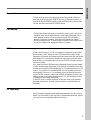
On operation
To turn on the projector after the projector has been turned off due to a
brief loss of power, press the POWER ON key on the remote control, or
turn off the MAIN POWER switch so that the STANDBY indicator turns
off and then turn on the MAIN POWER switch.
On cleaning
•To keep the cabinet looking new, periodically clean it with a soft cloth.
Stubborn stains may be removed with a cloth lightly dampened with a
mild detergent solution. Never use strong solvents, such as thinner,
benzene, or abrasive cleansers, since these will damage the cabinet.
•Avoid touching the lens. To remove dust on the lens, use a soft dry cloth.
Do not use a damp cloth, detergent solution, or thinner.
CRT burns
When a static picture of a VCR or a computer is displayed for more than
about an hour, a CRT burn may result. This means that an after-image
impression of the static picture remains on the screen even after the picture
has changed. If it is necessary to display the same static picture for more
than an hour, we recommend that you set the CONTR (contrast) control to
the lowest setting.
Also, when a picture of different size is displayed beyond a certain length
of time, an after-image impression of the frame of the smaller picture may
be burnt on the screen (such as displaying a 16:9 wide size picture on a 4:3
screen). To avoid this, we recommend that you use the same picture size
when possible. However, if it is necessary to use a different picture size,
set the CONTR (contrast) control and the BRT (brightness) control of the
smaller picture to the lowest setting possible. This will minimize the risk
of creating an after-image impression.
If the CRT burns, it must be replaced. In this case, refer to the warranty
provided with this unit. Consult your Sony dealer or Qualified Service
Personnel.
On repacking
Save the original shipping carton and packing material; they will come in
handy if you ever have to ship your unit. For maximum protection, repack
your unit as it was originally packed at the factory.
Overview

10
Features
Multiscan projector
This projector accepts and automatically detects horizontal scanning
frequencies between 15 kHz and 110 kHz and vertical scanning
frequencies between 38 Hz and 150 Hz.
In addition to high-resolution pictures from computers, you can also
project pictures from teletext decoders, VCRs and video cameras.
High resolution and brightness
A newly developed 8-inch electromagnetic focus CRT, a hybrid Sony
HACC (High-resolution Aspherical and Color Corrected) lens and a wide-
range cathode/G1 dual-drive video output circuit are incorporated in the
projector to provide a sharp and bright high-quality picture with the high
resolution of 1700 × 1200 pixels and the high light output of 240 lumen.
High contrast
The adoption of the optical coupling technologies, double-focus lens
system and an anti-reflection coating gives a fine-detail and sharp picture
with improved contrast in corners and screen center.
Easy operation—remote control, on-screen display
Adjustments such as input selection, picture control and centering
adjustment can be remotely controlled from both the front and rear of the
projector with the supplied remote control. You can also use the control as
a wired remote control by connecting it to the projector with the supplied
remote control cable.
Compatible with various color systems
NTSC, PAL, SECAM, NTSC4.43
1)
or PAL-M color system can be selected
automatically or manually.
Flexible setup
You can project a 60- to 300-inch picture (120-inch standard) with this
projector. The projector can be set up on the floor or ceiling, for front or
rear projection to suit the installation location, surrounding illumination,
usage, etc.
Illuminated control panel/remote control keys
The key names on the remote control and the control panel of the projector
can be illuminated for easy access in a dark place by pressing the LIGHT
button.
..........................................................................................................................................................................................................
1) NTSC4.43 is the color system used when playing back a video recorded on NTSC on a NTSC4.43 system VCR.

11
Location and Function of Controls
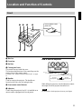
Front
How to open the control
panel cover
1 Blue lens
2 Green lens
3 Red lens
4 Control panel cover
The control keys are inside the cover.
The locations and functions of the control keys are the
same as those of the remote control.
For details, see “Remote Control/Control Panel” on page
15.
5 Handles
Used for carrying the projector. The handles are
located on the front, rear, left and right sides.
6 Front remote control detector
7 Adjusters
Used to keep the projector level if it is installed on an
uneven surface (equipped with four adjusters).
How to use the adjusters
While lifting the projector, turn the adjusters to adjust
the height so that the projector becomes level.
Note
Be careful not to let the projector down on your fingers.
To raise
the projector
To lower
the projector
1
23 4
56 7

12
Location and Function of Controls
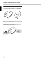
Using the handles
Pull out the front and rear handles or the side handles.
Putting away the handles
Push the handle release lever under each handle. The
handle is automatically retracted.

13
IR
POWER
STANDBY
AC IN
MAIN POWER
ONOFF
100~120V 15A 250V
200V~240V T6.3A 250V
R-Y
R
P
R
G
Y
B-Y
B
P
B
SYNC
HD
VD
INPUT A
S VIDEO
OUT
IN
C IN
Y IN
VIDEO
OUT
IN
ABL LINK
OUT
IN
TRIGGER
IN
PLUG IN
POWER
OUT
REMOTE
INDEX
RS-422A
CONTROL S
IN OUT
MODE
REMOTE1
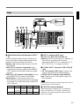
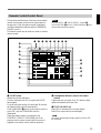
Rear
1 Signal interface board attachment part (INPUT
B)
The IFB-40 Signal Interface Board is installed at the
factory. Other optional signal interface boards can be
attached to this section instead of the IFB-40.
Indicator (red): Lights up when the input of the IFB-
40 is selected.
REMOTE 1 IN connector (14-pin multi): When
connecting two projectors, connect to the REMOTE
1 OUT connector on the IFB-40 installed to another
projector.
REMOTE 1 OUT connector (14-pin multi): Connect
to the REMOTE 1 IN connector on the IFB-40.
MODE selector: Turn the control switch of the
MODE selector to the appropriate position according
to the length of the cable connected to the REMOTE
1 OUT connector.
Cable length
Type of cable
Position
2 INPUT A connectors (BNC type)
R/R-Y/P
R, G/Y, B/B-Y/PB, SYNC/HD, VD
connectors: Connect to the outputs of a computer or a
video camera. According to the connected
equipment, the RGB (R, G, B), component (R-Y, G,
B-Y) or HDTV (P
R, Y, PB) signal is selected.
3 S VIDEO IN/OUT connectors (VPH-G70Q/QM
only)
Y IN, C IN connectors (BNC type): Connects to the
Y and C video outputs of the video equipment.
S VIDEO IN/OUT connectors (4-pin, mini-DIN
type): Connects to the S video output or input of the
video equipment.
Note
The S VIDEO IN connector is disconnected when a cable is
connected to the Y/C IN connectors.
4 TRIGGER connector (minijack)
When the projector is turned on, 5 V is output and
when it is turned off, 0 V is output. However, the
connector is not used as the power source since the
power is not output.
up to 2 m
SIC-M-1
CCQ-2BRS
1
up to 25 m
SIC-M-15
CCQ-25BRS
SIC-M-25
3
up to 10 m
SIC-M-5
CCQ-5BRS
CCQ-10BRS
2
up to 50 m
SIC-M-50
CCQ-50BRS
4
1
2
34
5
!™
!£
!¢
!∞
67 8 9
!º
!¡

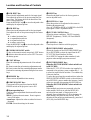
14
Location and Function of Controls
!¡ MAIN POWER switch
!™ Error code window
An error code lights up when an operational error
occurs.
!£ POWER indicator
Lights in green when the power is turned on.
!¢ STANDBY indicator
Lights in orange when the MAIN POWER switch is
turned on. Once in the standby mode, you can turn the
projector on and off with the remote control.
!∞ Rear remote control detector
5 RS-422A REMOTE connector (D-sub 9-pin)
Used to expand the system connections using the RS-
422A interface.
Before using the connector, loosen the two screws to
remove the cap.
6 VIDEO IN/OUT connectors (VPH-G70Q/QM
only)
VIDEO IN connector (BNC type): Connects to the
composite video output of the video equipment.
VIDEO OUT connector (BNC type): Connects to the
composite video input of a color monitor.
7 ABL (Automatic Brightness Limiter) LINK IN/
OUT jacks (minijack)
When connecting multiple projectors, connects the
ABL LINK OUT jack to the ABL LINK IN jack on
another projector. You can synchronize the brightness
limiting point among the projectors, allowing to make
the whole screen brightness uniform.
8 CONTROL S jacks
IN/PLUG IN POWER (5 V) jack (stereo minijack):
Connects to the CONTROL S OUT jack of other
Sony equipment. Also connects to the CONTROL S
OUT jack of the supplied remote control with the
supplied remote control cable (stereo cable) to be
used as a wired remote control. In this case, this jack
supplys 5 V to the remote control as power source.
OUT jack (stereo minijack): Connects to the
CONTROL S IN jack of other Sony equipment.
Note
When using this jack, the remote control detector on the
projector does not function.
9 INDEX NO. switches
When multiple projectors are connected, set the index
number of each projector.
To display the index number on the screen, press the
NORMAL key, and the ENTER key on the remote
control.
Note
If you set the index number to “00,” the projector does not
operate.
!º AC IN socket
Connect the supplied AC power cord.

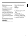
15
Remote Control/Control Panel
Note
The VOLUME +/– !¢, INPUT SELECT, C and D !¶,
AUDIO MUTING @¡ and LCD LENS CONTROL @™ keys
do not function with this projector.
The locations and functions of the keys on the remote
control are the same as those on the control panel of
the projector. (Only the remote control is equipped
with the transmission indicator and the COMMAND
ON/OFF switch.)
The remote control may be used as a wired or wireless
remote control.
1 LIGHT button
Illuminates the key indicators.
The key indicators turn off if you press the LIGHT
button again.
If you do not press any key for more than 30 seconds,
the indicators also turn off automatically.
If the COMMAND 6 switch on the remote control is
set to OFF, only the COMMAND switch is
illuminated.
When the remote control is connected to the
CONTROL S IN/PLUG IN POWER jack of the
projector via the remote control cable, the power is
supplied to the remote control from the projector.
2 Transmission indicator (only for the remote
control)
Lights each time you press a key. If it does not light,
replace the batteries with new ones.
3 STATUS ON/OFF key
Press OFF to eliminate the on-screen display.
Press ON to restore the on-screen display.
Note
The menus and warning messages appear even if the OFF
key is pressed.
PIC
ON
AUDIO OFF
PATTERN
FOCUS
ZOOM
SHIFT
NORMAL
MUTING
STATUS
LCD LENS CONTROL
ON
COMMAND
OFF
SIZE
SHIFT
RGB
R
B
CENT
ON
OFF
POWER
MEMORY
MENU
VIDEO SELECT
INPUT SELECT
A D
B
C
BLKG
RESET
1
423
5
8
67
9
INDEX
0(ALL)
SECOND
SWITCHER/INDEX
SWITCHER
ENTER
POSITION
BRIGHT
CONTR
PICTURE CONTROL
HUE COLOR
SHARP VOLUME
LIGHT
VIDEO/S VIDEO
!•
!ª
@º
@¡
@™
@£
!¶
!§
!£
!∞
!¢
9
!º
!¡
!™
4
32
1
5
6
7
8

16
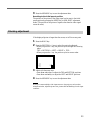
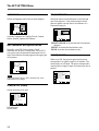
4 RGB SHIFT key
Enters the shift adjustment mode for the input signal.
Next adjust the position of the picture using the four
arrow keys. The picture shifts in the direction of the
arrow on the pressed key.
Press the MEMORY key 8 to store the adjusted value
and display the adjusted picture.
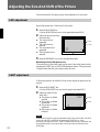
5 RGB SIZE key
Enters the size adjustment mode for the input signal.
Next adjust the size of the picture using the four arrow
keys.
B : to reduce horizontal size
b : to expand horizontal size
V : to expand vertical size
v : to reduce vertical size
Press the MEMORY key 8 to store the adjusted value
and display the adjusted picture.
6 COMMAND ON/OFF switch
No key on the remote control except the LIGHT button
1 function when this switch is set to OFF. This saves
the battery power.
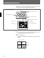
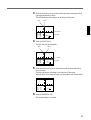
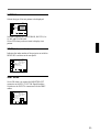
7 CENT R/B keys
Enter the centering adjustment mode of the red and
blue.
R: Press to enter the red centering adjustment mode.
B: Press to enter the blue centering adjustment mode.
Perform the centering adjustment using the four arrow
keys.
8 MEMORY key
Stores various adjusted data into memory.
9 POWER ON/OFF keys
Turn on and off the projector when the MAIN
POWER switch on the projector is set to ON.
0 Menu operation keys
Used for various adjustment functions and for menu
operations.
MENU: Displays the main menu. Press it again to
turn off the menu.
Arrow keys: Adjusts the value or selects the item in
the menu.
ENTER: Stores the settings in the menu.
!¡ RESET key
Resets the adjusted levels to the factory preset or
service adjusted levels.
!™ POSITION +/– keys
Select the position to be adjusted on the screen in
blanking adjustment mode.
Also, set V SHIFT to WIDE or NARROW in the RGB
input signal’s SHIFT adjustment mode.
!£ PICTURE CONTROL keys
Adjust the picture conditions: CONTR (contrast),
BRIGHT (brightness), COLOR, HUE and SHARP
(sharpness).
!¢ VOLUME +/– keys
These keys do not function with this projector.
!∞ SWITCHER/INDEX select switch
Selects the function of the SWITCHER/INDEX keys.
Set to SWITCHER to select the input from the PC-
1271/1271M Signal Interface Switcher.
Set to INDEX to assign the index number of each
projector when multiple projectors are used.
!§ SWITCHER/INDEX keys
When the SWITCHER/INDEX select switch is set
to SWITCHER
When the PC-1271/1271M switcher (not supplied) is
connected to the projector, press a number key (1 – 8)
to select the input from the switcher. The number key
9 does not function.
To select the input from the second switcher (when the
SINGLE/SECOND/OTHER switch on the switcher is
set to SECOND), press a number key between 1 and 8
within two seconds after pressing the SECOND key.
When the SWITCHER/INDEX select switch is set
to INDEX
When multiple projectors are connected, select the
index number, which is set with the INDEX NO.
switch on the rear panel, of the projector to be
adjusted. Press a number key (1 – 9) to designate the
index number, then press the ENTER key. When
adjusting all the projectors simultaneously, press the 0
(ALL) key, then the ENTER key.
Location and Function of Controls

17
!¶ INPUT SELECT keys
Select the input signal.
VIDEO: VPH-G70Q/QM The video or S video
signal input from the VIDEO IN or S VIDEO IN (or
Y/C IN) connectors
VPH-G70QMG Video or S video signal input from
the optional IFB-G70QMG Video Interface Board
(when installing the IFB-G70QMG to the projector)
SELECT VIDEO/S VIDEO: VPH-G70Q/QM
Selects the signal input from the VIDEO IN or S
VIDEO IN (or Y/C IN) connectors by pressing this
key after pressing the VIDEO key.
VPH-G70QMG Selects video or S video signal
input from the optional IFB-G70QMG (when
installing the IFB-G70QMG to the projector) after
pressing the VIDEO key.
A: The RGB, component or HDTV signal input from
the INPUT A connectors of the projector
B: The signal input from the INPUT B section when
the optional interface board other than the IFB-40 is
installed
C, D: These keys do not function with this projector.
Note
To switch the input signal from the INPUT A or INPUT B
to the S VIDEO IN (or Y/C IN) connectors, first press the
VIDEO key, then press the SELECT VIDEO/S VIDEO key.
!• BLKG (blanking) key
Enters the blanking adjustment mode.
You can adjust the blanking with the four arrow keys.
!ª PATTERN key
Displays the internal test patterns of the projector.
Each press of the key displays CROSS HAIR,
HATCH (9 × 9), ME and COLOR BAR patterns,
sequentially.
@º NORMAL key
Erases the test pattern or cancels the various
adjustment modes.
@¡ MUTING keys
PIC (picture): Cuts off the picture. To restore the
picture, press the key again.
AUDIO: This key does not funcion with this
projector.
@™ LCD LENS CONTROL keys
These keys do not function with this projector.
@£ CONTROL S OUT jack (only for the remote
control)
Connects to the CONTROL S IN/PLUG IN POWER
jack on the projector for wired remote control
application.

18
IN
PLUG IN
POWER
OUT
CONTROL S
Notes on wireless remote control operation
•Be sure that there is nothing to obstruct the infrared
beam between the remote control and the projector.
•The operation range is limited. The shorter the
distance between the remote control and the
projector, the wider the angle within which the
remote control can control the projector.
•The remote control detectors on the projector do not
operate when the remote control is being used as a
wired remote control. If you wish to use the remote
control as a wireless remote control, be sure to
remove the connecting cable from both the remote
control and the projector.
Connecting the remote control to the
projector
Location and Function of Controls
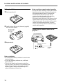
Battery installation
1 Push to open the lid.
2 Install the three R6 (size AA) batteries (supplied)
with the correct polarity.
3 Replace the lid.
Notes on batteries
•Be careful that the battery orientation is correct when
inserting batteries.
•Do not mix old battery with new one, or different
types of batteries.
•If you do not intend to use the remote control for a
long time, remove the batteries to avoid damage from
battery leakage. If a battery has leaked, remove the
batteries, wipe the battery compartment dry and
replace the batteries with new ones.
Rear of the projector
CONTROL
S OUT
Be sure to install
the battery from
the ’ side.
CONTROL S IN
Remote control cable
(supplied)

19
Projecting
Projecting
ONOFF
MAIN POWER
SELECT
SWITCHER
INDEX
PIC ONAUDIO OFF
PATTERN
FOCUS
ZOOM
SHIFT
NORMAL
MUTING
STATUS
LCD LENS CONTROL
ON
COMMAND
OFF
RGB
SHIFT
R
B
CENT
ONOFF
MEMORY
MENU
VIDEO
INPUT SELECT
ADBC
BLKG
RESET
1423
5867
9
0(ALL)
SECOND
SWITCHER/INDEX
ENTER
POSITION
BRIGHT
CONTR
PICTURE CONTROL
HUE
COLOR
SHARP
VOL
VIDEO/S VIDEO
LIGHT
POWER
SHIFT
1, 6
2
6
5
4
Front remote control detector
MENU key
SWITCHER/INDEX select switch
and number keys
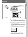
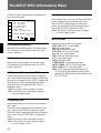
1 Press the MAIN POWER switch on the rear of the projector.
The u STANDBY indicator lights in orange and the projector goes
into the standby mode.
2 Press the POWER ON key on the remote control or the control panel.
The POWER indicator lights in green.
A white screen with the message shown below (warming up screen)
appears on the screen. Make sure to allow the projector to warm up for
20 minutes after turning it on.
The message disappears temporarily in about 35 seconds, and will
appear subsequently for 5 seconds every 30 seconds.
Press the MENU key to cancel the warming up screen and see the
picture immediately after the projector is turned on if, for example, the
adjustment has been finished and warming up is not needed.
(continued)
INPUT-A
For optimum
performance
white screen will
remain for 20min.
For immediate use,
push [MENU] key.
u STANDBY indicator/
POWER indicator/
Rear remote control detector
Control panel (inside the cover)
Remote control
Point it toward the front
remote control detector.

20
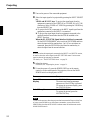
3 Turn on the power of the connected equipment.
4 Select the input signal to be projected by pressing the INPUT SELECT
key.
VIDEO and SELECT keys: To project the signal input from the
equipment connected to the VIDEO IN or S VIDEO IN (or Y/C IN)
connectors. Select VIDEO or S VIDEO by pressing the VIDEO key,
then the SELECT key.
A: To project the RGB, component or the HDTV signal input from the
equipment connected to the INPUT A connectors.
B: To project the signal input from the equipment connected to the
optional interface board other than the IFB-40 installed to the
INPUT B section.
When the PC-1271/1271M Signal Interface Switcher is connected:
Set the SWITCHER/INDEX select switch to SWITCHER and then
select the input with the number keys 1 to 8. If two switchers are
connected, press the SECOND key and then the number key to
select the input from the second switcher.
Note
When you select the input signal connected to the INPUT A or INPUT B section,
be sure to select the correct signal in the SET SETTING menu. If an incorrect
signal is selected, picture may be distorted.
For details, see “The SET SETTING Menu” on page 33.
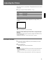
5 Adjust the picture.
For details, see “Adjusting the picture” on page 21.
6 To turn the power off, press the POWER OFF key on the remote
control or on the control panel of the projector, then set the MAIN
POWER switch on the projector to OFF.
Note
To turn on the projector after the projector has been turned off due to a brief loss
of power, press the ON key on the remote commander, or turn off the MAIN
POWER switch so that the STANDBY indicator turns off and then turn on the
MAIN POWER switch.
Projecting
To Press
Turn off the on-screen the STATUS OFF key.
display The menus and warning messages
appear even if the OFF key is pressed.
To restore the on-screen display, press
the STATUS ON key.
Cut off the picture the MUTING PIC key.
To restore the picture, press the
MUTING PIC key.
La pagina si sta caricando...
La pagina si sta caricando...
La pagina si sta caricando...
La pagina si sta caricando...
La pagina si sta caricando...
La pagina si sta caricando...
La pagina si sta caricando...
La pagina si sta caricando...
La pagina si sta caricando...
La pagina si sta caricando...
La pagina si sta caricando...
La pagina si sta caricando...
La pagina si sta caricando...
La pagina si sta caricando...
La pagina si sta caricando...
La pagina si sta caricando...
La pagina si sta caricando...
La pagina si sta caricando...
La pagina si sta caricando...
La pagina si sta caricando...
La pagina si sta caricando...
La pagina si sta caricando...
La pagina si sta caricando...
La pagina si sta caricando...
La pagina si sta caricando...
La pagina si sta caricando...
La pagina si sta caricando...
La pagina si sta caricando...
-
 1
1
-
 2
2
-
 3
3
-
 4
4
-
 5
5
-
 6
6
-
 7
7
-
 8
8
-
 9
9
-
 10
10
-
 11
11
-
 12
12
-
 13
13
-
 14
14
-
 15
15
-
 16
16
-
 17
17
-
 18
18
-
 19
19
-
 20
20
-
 21
21
-
 22
22
-
 23
23
-
 24
24
-
 25
25
-
 26
26
-
 27
27
-
 28
28
-
 29
29
-
 30
30
-
 31
31
-
 32
32
-
 33
33
-
 34
34
-
 35
35
-
 36
36
-
 37
37
-
 38
38
-
 39
39
-
 40
40
-
 41
41
-
 42
42
-
 43
43
-
 44
44
-
 45
45
-
 46
46
-
 47
47
-
 48
48


Sony VPH-G70Q Operating Instructions Manual
- Categoria
- Proiettori di dati
- Tipo
- Operating Instructions Manual
- Questo manuale è adatto anche per
in altre lingue
- English: Sony VPH-G70Q
Documenti correlati
Altri documenti
-
Infocus C440 Manuale utente
-
Barco GRAPHICS 1208s Manuale utente
-
Analog way Eikos Manuale utente
-
-
-
-
-
BenQ MX661 Manuale utente
-
-
Zenith PRO1200X Guida d'installazione