Analog way Eikos Manuale utente
- Categoria
- Convertitori video
- Tipo
- Manuale utente
Questo manuale è adatto anche per

version 4.10
USER MANUAL
Eikos


THANK YOU
1
Thank you for choosing Analog Way. By following these simple steps, you should be able to operate
the powerful Eikos (EKS500).
TABLE OF CONTENTS
INTRODUCTION
1-1. EIKOS OPERATING MODES
1-2. USEFUL TERMS AND DEFINITIONS
1
5
5
6
7
HARDWARE INSTALLATION
2-1. SAFETY INSTRUCTION
2-2. UNPACKING AND INSPECTION
2-3. RACKMOUNT INFORMATION
2-4. CABLE & ADAPTOR INFORMATION
2-5. HARDWARE SPECIFICATIONS
7
12
12
12
13
CONNECTING THE EIKOS
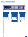
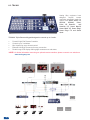
3-1. CONNECTING THE EIKOS
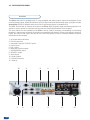
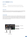
3-2. THE EIKOS REAR PANEL
23
24
23
Mixer Mode
Matrix Mode
Quadravision Mode
Input specications
Output specications
Communication specications
Environmental specications
Pin outs
HDCP compliance
Overview
Inputs #1 to #6
DVI Inputs #1 and #2
3G/HD/SD-SDI Inputs #1 and #2
Preview Outputs
Main Outputs

2
OPERATING THE EIKOS
4-2. THE EIKOS MENU
4-3. WORKING WITH THE EIKOS
• A- Settings in Mixer Mode
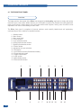
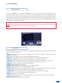
4-1. THE EIKOS FRONT PANEL
28
28
31
32
34
Overview
On/Off button
Menu screen
Menu scroll knob
Control section
Layer selection section
Input selection section
Toggle Preset
Freeze button
Take button
Quadravision selection button
Adjustment
Effect Selection button
Preset Selection button
Menu navigation
Preview Id
Home menu
Source Input selection
Input selection settings
Input Sync. Loss Function
Source output selection
Output selection settings
Preview Features
Preview Mode & OSD Settings
How to use the Mosaic Preview Feature
Working with Layers
Working with Layers Functions
Opening transitions and closing Live Layers
Working with PIPs
PIP adjustment menu
PIP conguration
PIP as Layers
PIPs with Transitions & Borders
Capturing still Frames
Working with Frames
Memorizing Frames
Opening transitions & closing Still Layers
Frame input setup menu
Frames as Layer
Layer Transitions & effects
Mixer Functions
Capturing Logos
Capturing an Animated Logo
Memorizing Logos
Logos input setup menu
Working with Logos
Logos as Layers
Working with Presets
Operating modes
Reseting default values
Eikos color codes

HOME MENU
REMOTE CONTROL SOFTWARE
5-1. THE EIKOS RCS
5-2. WORKING WITH THE RCS
70
61
70
73
• B- Settings in Native Matrix Mode
• C- Settings in Quadravision Mode
Source Input selection
Output selection settings
Input selection settings
Working with Native Matrix Mode
Working with Cut, Fade or Transitions
Working with Mirror Mode
Source Output selection
Working with Layers
Working with PIP
Working with Frames/Logos
Working with Templates
Working with Presets
Creating a Preset
Working with Frames/Logos
RCS presentation
How to use the RCS
Software installation
Serial connection
Ethernet connection
Software overview
Working with PIPs
PIP conguration
Working with Frames
Operating Mode
Source input conguration
Source output conguration
Layer transitions & effects
Working with Audio
Creating Presets
Audio conguration
Memorizing Frames
Working with Logos
Memorizing Logos
Working with Presets
53
58
3
Creating Presets
Working with audio
Audio conguration
Special Features

HOW TO CONTACT US
INFORMATION ON DISPOSAL
88
CONTACT INFORMATION
88
88
WARRANTY AND SERVICES INFORMATION
87
8-1. ANALOG WAY LIMITED WARRANTY
8-2. SERVICES AND RMA
87
87
APPLICATION NOTES AND TIPS
7-1. ABOUT APPLICATION NOTES
7-2. APPLICATION NOTES
7-3. EXTERNAL PROGRAMMING
82
82
82
86
4
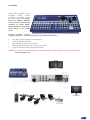
OPTIONAL REMOTE CONTROL SYSTEMS
6-1. Axion 2 - Ref. ARC200
6-2. Orchestra - Ref. ORC50
6-3. TRK-800 - Ref. TRK-800
6-4. RK-300 - Ref. RK-300
78
78
79
80
81

INTRODUCTION
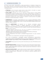
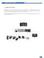
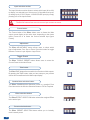
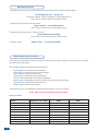
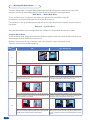
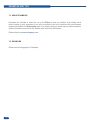
1-1. THE EIKOS (EKS500) OPERATING MODES
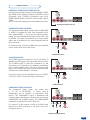
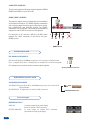
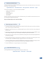
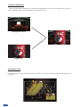
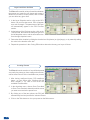
This mode allows for a single Eikos to seamlessly switch and blend
any of its 12 analog/digital inputs with any other of the inputs, add PIP,
titling or logo insertion to the live frame, while previewing your every
move before going live, to avoid embarrassing errors on your main
screen. The Mixer mode is the Eikos native mode, and with no less
than 6 layers (of which 3 live layers). The Video output of the Eikos
allows to have a full Main screen for recording or broadcasting.
MIXER MODE
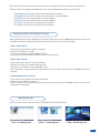
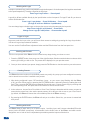
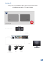
MATRIX MODE
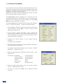
Before you start setting up your Eikos for the rst time, be sure you know what you actually want to do with
it. The Eikos offers a choice of three operating modes, which results in a versatile video production tool for
live event staging and xed installation applications.
* NOTE * : We recommend resetting the device to its default values every time you set up your shows or
events (see the “Operating The Eikos” chapter, p28).
This mode turns your Eikos into a true 12 x 2 scaled matrix, while preserving seamless switching capabilities.
Main and Preview outputs can be set to different resolutions and rates. Switching between any of the inputs
can be done with the various effects (Cut, Fade, Slides…) and synchronized on both outputs.
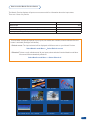
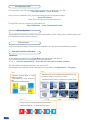
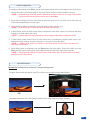
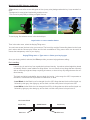
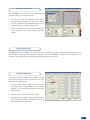
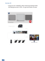
This mode allows to display up to four live windows, while preserving seamless switching capabilities. Several
templates are available.
QUADRAVISION MODE
5
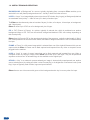
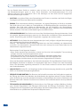
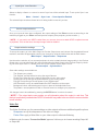
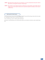
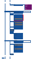
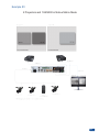
Logo 2*
Logo 1
Layer B
Layer D*
Layer A
Layer C
Background Frame
* Depending on which mode is selected

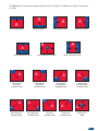
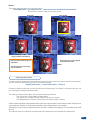
PIP: a “PIP” (Picture In Picture), is a picture, typically of reduced size, which is positioned over another
background image or PIP. PIPs can be reduced, enlarged and bordered. PIPs can overlap, depending on
their visual priority.
Eikos allows for Dynamic PIP on the opening and closing of the sequence, vertically or horizontally. A “ying”
PIP is also possible over the screen with vertical, horizontal or diagonal animation. A PIP is considered as a
live layer.
FRAME: a “Frame” is a full screen image which is selected from one of the eight still frames which you can
capture with the Eikos. A Frame can be ash captured and imported from any video or computer source
plugged into the machine.
LOGO: a “Logo” is a part of screen image that can be ash captured and imported from any Video or
Computer source, by keying or image cut-out. Eikos can record up to 8 still logos. They can be positioned
anywhere on the screen. An animated logo is also available on the eighth input.
KEYING: a “Key” is an electronic process whereby an image is electronically superimposed over another
source or background, by cutting out either a color Chroma Key), or its brightness or luminance levels (Luma
Key). Keys are typically used for titles, logos and special effects.
Eikos allows to use a live source with green or blue background and to key it over any other live input.
1-2. USEFUL TERMS AND DEFINITIONS
BACKGROUND: a “Background” is a source, typically originating from a computer. Eikos enables you to
work with live or still (frame) background sources - visually in back of all other sources.
LAYER: a “Layer” is an image display element (such as a PIP window, Key, Logo(s) or Background) that has
an associated visual priority — either in front (or in back) of another layer.
The Eikos can simultaneously view no less than 6 layers (3 video, or live layers, 1 frame layer, or background,
and 2 logo layers).
Eikos can insert up to 2 PIPs on a live background, plus 2 logos.
6

CAUTION:
All of the safety and operating instructions should be read before the product is operated and should be
maintained for further reference. Please follow all of the warnings on this product and its operating instructions.
• WARNING: To prevent the risk of electric shock and re, do not expose this device to rain, humidity,
intense heat sources (such as heaters and direct sunlight). Slots and openings in the device are provided
for ventilation and to avoid overheating. Make sure the device is never placed near a textile surface that
could block the openings. Also keep away from excessive dust, vibrations and shocks.
• POWER: Only use the power supply indicated on the device of the power source. Devices equipped with
a grounding plug should only be used with a grounding type outlet. In no way should this grounding be
modied, avoided or suppressed.
• POWER CORD: The device is equipped with a main switch (On (I) /Off (O)). The Switch ON and OFF is
initiated by the main switch.
Caution: The power cord constitute the only mean to totaly disconnect the equipment
from the main power.
Apply the following guidelines :
- The equipment connected to the network must have a release system easily
accessible and located outside the unit.
- Unplug the power cord, do not pull on the power cord but always on the plug itself.
- The outlet should always be near the device and easily accessible.
- Power supply cords should be routed so that they are not likely to be walked on or
pinched by items placed upon or against them.
If the power supply cord is damaged, unplug the device. Using the device with a damaged power supply cord
may expose your device to electric shocks or other hazards. Verify the condition of the power supply cords
once in a while. Contact your dealer or service center for replacement if damaged.
• CONNECTIONS: All inputs and outputs (except for the power input) are TBTS dened under EN60950.
• SERVICING: Do not attempt to service this product yourself by opening or removing covers and screws
since it may expose your device to electric shocks or other hazards. Refer all problems to qualied
service personnel.
• OPENINGS: Never push objects of any kind into this product through the openings. If liquids have been
spilled or objects have fallen into the device, unplug it immediately and have it checked by a qualied
technician.
HARDWARE INSTALLATION
SAFETY INSTRUCTIONS
2-1. SAFETY INSTRUCTIONS
7

An de mieux comprendre le fonctionnement de cet appareil nous vous conseillons de bien lire toutes les
consignes de sécurité et de fonctionnement de l’appareil avant utilisation. Conservez les instructions de
sécurité et de fonctionnement an de pouvoir les consulter ultérieurement. Respectez toutes les consignes
marquées dans la documentation, sur le produit et sur ce document.
• ATTENTION: An de prévenir tout risque de choc électrique et d’incendie, ne pas exposer cet appareil à
la pluie, à l’humidité et aux sources de chaleur intense.
• INSTALLATION: Veillez à assurer une circulation d’air sufsante pour éviter toute surchauffe à l’intérieur
de l’appareil. Ne placez pas l’appareil sur ou à proximité d’une surface textile susceptible d’obstruer
les orices de ventilation. N’installez pas l’appareil à proximité de sources de chaleur comme un
radiateur ou une poche d’air chaud, ni dans un endroit exposé au rayonnement solaire direct, à des
poussières excessives, à des vibrations ou à des chocs mécaniques. Ceci pourrait provoquer un mauvais
fonctionnement et un accident.
• ALIMENTATION: Ne faire fonctionner l’appareil qu’avec la source d’alimentation indiquée sur l’appareil.
Les appareils doivent être obligatoirement connectés sur une source équipée d’une mise à la terre efcace.
En aucun cas cette liaison de terre ne devra être modiée, contournée ou supprimée.
• CORDON D’ALIMENTATION: Les appareils sont équipés d’un interrupteur général (Marche I / Arrêt
O), la mise en tension et la mise hors tension se fait en actionnant cet interrupteur général. Attention :
le cordon d’alimentation constitue le seul moyen de débrancher l’appareil totalement de l’alimentation
secteur. Pour être certain que l’appareil n’est plus alimenté, ce cordon doit être débranché de la prise
murale.
Appliquer les consignes suivantes :
- Le matériel relié à demeure au réseau, doit avoir un dispositif de sectionnement facilement accessible
qui doit être incorporé à l’extérieur de l’appareil.
- Débrancher le cordon d’alimentation de la prise murale si vous prévoyez de ne pas utiliser l’appareil
pendant quelques jours ou plus.
- Pour débrancher le cordon, tirez-le par la che. Ne tirez jamais sur le cordon proprement dit.
- La prise d’alimentation doit se trouver à proximité de l’appareil et être aisément accessible.
- Ne laissez pas tomber le cordon d’alimentation et ne posez pas d’objets lourds dessus.
Si le cordon d’alimentation est endommagé, débranchez-le immédiatement de la prise murale. Il est
dangereux de faire fonctionner un appareil avec un cordon endommagé; un câble abîmé peut provoquer un
risque d’incendie ou un choc électrique. Vériez le câble d’alimentation de temps en temps. Contactez votre
revendeur ou le service après-vente pour un remplacement.
• CONNEXIONS: Toutes les entrées et sorties (exceptée l’entrée secteur) sont de type TBTS (Très Basse
Tension de Sécurité) dénies selon EN 60950.
• RÉPARATION ET MAINTENANCE: L’utilisateur ne doit en aucun cas essayer de procéder aux opérations
de dépannage, car l’ouverture des appareils par retrait des capots ou de toutes autres pièces constituant
les boîtiers ainsi que le dévissage des vis apparentes à l’extérieur, risquent d’exposer l’utilisateur à des
chocs électriques ou autres dangers. Contactez le service après-vente, votre revendeur ou s’adresser à
un personnel qualié uniquement.
• OUVERTURES ET ORIFICES: Les appareils peuvent comporter des ouvertures (aération, fentes, etc...),
veuillez ne jamais y introduire d’objets et ne jamais obstruer ses ouvertures. Si un liquide ou un objet
pénètre à l’intérieur de l’appareil, débranchez immédiatement l’appareil et faites-le contrôler par un
personnel qualié avant de le remettre en service.
INSTRUCTIONS DE SECURITE
8

Allo scopo di capire meglio il funzionamento di questa apparecchiatura vi consigliamo di leggere bene
tutti i consigli di sicurezza e di funzionamento prima dell’utilizzo. Conservare le istruzioni di sicurezza e di
funzionamento al ne di poterle consultare ulteriormente. Seguire tutti i consigli indicati su questo manuale
e sull’apparecchiatura.
• ATTENZIONE: Al ne di prevenire qualsiasi rischio di shock elettrico e d’incendio, non esporre
l’apparecchiatura a pioggia, umidità e a sorgenti di eccessivo calore.
• INSTALLAZIONE: Assicuratevi che vi sia una sufciente circolazione d’aria per evitare qualsiasi
surriscaldamento all’interno dell’apparecchiatura. Non collocare l’apparecchiatura in prossimità o su
superci tessili suscettibili di ostruire il funzionamento della ventilazione. Non installate l’apparecchiatura
in prossimità di sorgenti di calore come un radiatore o una fuoruscita d’aria calda, né in un posto esposto
direttamente ai raggi del sole, a polvere eccessiva, a vibrazioni o a shock meccanici. Ció potrebbe
provocare un erroneo funzionamento e un incidente.
• ALIMENTAZIONE: Far funzionare l’apparecchiatura solo con la sorgente d’alimentazione indicata
sull’apparecchiatura. Le apparecchiature queste devono essere obbligatoriamente collegate su una
sorgente fornita di una efciente messa a terra. In nessun caso questo collegamento potrà essere
modicato, sostituito o eliminato.
• CAVO DI ALIMENTAZIONE: Gli apparecchi con un interrutore (commutatore) generale
(Accesso I : Speuto 0), accendere ou spagnere l’apparecchio si fa usando l’interrutore.
Attenzione: il cavo di alimentazione è il solo modo di disconnettere l’apparecchio dell’alimentazione. Per
assicurarsi che totalemente l’apparecchio non è più collegato, il cavo deve essere disconesso della presa
murale.
Seguire le instruzioni seguenti :
- Il materiale collegato a residenza alla rete, deve avere un dispositivo di sezionamento facile da
raggiongere eche deve essere inserito all’esterno del apparecchio.
- Disconnettere l’apparecchiatura dalla presa murale se si prevede di non utilizzarla per qualche giorno.
- Per disconnettere il cavo tirare facendo forza sul connettore.
- La presa d’alimentazione deve trovarsi in prossimità dell’apparecchiatura ed essere facilmente
accessibile.
- Non far cadere il cavo di alimentazione né appoggiarci sopra degli oggetti pesanti.
Se il cavo di alimentazione é danneggiato, spegnere immediatamente l’apparecchiatura.
E’ pericoloso far funzionare questa apparecchiatura con un cavo di alimentazione danneggiato, un cavo
grafato puó provocare un rischio di incendio o uno shock elettrico. Vericare il cavo di alimentazione
spesso. Contattare il vostro rivenditore o il servizio assistenza per una sostituzione.
• CONNESSIONE: Tutti gli ingressi e le uscite (eccetto l’alimentazione) sono di tipo TBTS denite secondo
EN 60950.
• RIPARAZIONI E ASSISTENZA: L’utilizzatore non deve in nessun caso cercare di riparare l’apparecchiatura,
poiché con l’apertura del coperchio metallico o di qualsiasi altro pezzo costituente la scatola metallica,
nonché svitare le viti che appaiono esteriormente, poiché ció puó provocare all’utilizzatore un rischio di
shock elettrico o altri rischi.
• APERTURE DI VENTILAZIONE: Le apparecchiature possono comportare delle aperture di ventilazione,
si prega di non introdurre mai oggetti o ostruire le sue fessure. Se un liquido o un oggetto penetra
all’interno dell’apparecchiatura, disconnetterla e farla controllare da personale qualicato prima di
rimetterla in servizio.
INSTRUZIONI DI SECUREZZA
9

Um den Betrieb dieses Geräts zu verstehen, raten wir Ihnen vor der Inbetriebnahme alle Sicherheits
und Betriebsanweisungen genau zu lesen. Diese Sicherheits- und Betriebsanweisungen für einen
späteren Gebrauch sicher aufbewahren. Alle in den Unterlagen, an dem Gerät und hier angegebenen
Sicherheitsanweisungen einhalten.
• ACHTUNG: um jegliches Risiko eines Stromschlags oder Feuers zu vermeiden, das Gerät nicht Regen,
Feuchtigkeit oder intensiven Wärmequellen aussetzen.
• EINBAU: Eine ausreichende Luftzufuhr sicherstellen, um jegliche Überhitzung im Gerät zu vermeiden.
Das Gerät nicht auf und in Nähe von Textiloberächen, die Belüftungsöffnungen verschließen können,
aufstellen. Das Gerät nicht in Nähe von Wärmequellen, wie z.B. Heizkörper oder Warmluftkappe,
aufstellen und es nicht dem direkten Sonnenlicht, übermäßigem Staub, Vibrationen oder mechanischen
Stößen aussetzen. Dies kann zu Betriebsstörungen und Unfällen führen.
• STROMVERSORGUNG: Das Gerät nur mit der auf dem Gerät bezeichnete Stromquelle betreiben. Gerät
mit geerdeter Hauptstromversorgung muss an eine Stromquelle mit efzienter Erdung angeschlossen
werden. Diese Erdung darf auf keinen Fall geändert, umgangen oder entfernt werden.
• NETZKABEL: Da die Geräte über einen Hauptschalter (An I/ Aus 0) verfügen, erfolgt die Stromversorgung
und -unterbrechung über diesen Hauptschalter.
Achtung : Das Netzkabel stellt die einzige Möglichkeit dar, das Gerät vollständig vom Netzanschluss
zu trennen. Um sicherzustellen, dass das Gerät nicht mehr versorgt wird, muss dieses Kabel aus der
Netzsteckdose ausgesteckt werden.
Bitte beachten Sie die folgenden Hinweise :
- Wenn Geräte dauerhaft am Netz bleiben, müssen sie über eine leicht zugängliche Trennvorrichtung
verfügen, die außen am Gerät angebracht sein muss.
- Das Kabel mittels dem Stecker herausziehen. Niemals am Stromkabel selbst ziehen.
- Die Steckdose muß sich in der Nähe des Geräts benden und leicht zugänglich sein.
- Das Stromkabel nicht fallen lassen und keine schweren Gegenstände auf es stellen.
Wenn das Stromkabel beschädigt ist, das Gerät sofort abschalten. Es ist gefährlich das Gerät mit einem
beschädigten Stromkabel zu betreiben; ein abgenutztes Kabel kann zu einem Feuer oder Stromschlag
führen. Das Stromkabel regelmäßig untersuchen. Für den Ersatz, wenden Sie sich an Ihren Verkäufer
oder Kundendienststelle.
• ANSCHLÜSSE: Bei allen Ein- und Ausgängen (außer der Stromversorgung) handelt es sich, gemäß EN
60950, um Sicherheits Kleinspannunganschlüsse.
• REPARATUR UND WARTUNG: Der Benutzer darf keinesfalls versuchen das Gerät selbst zu reparieren,
die Öffnung des Geräts durch Abnahme der Abdeckhaube oder jeglichen anderen Teils des Gehäuses
sowie die Entfernung von außen sichtbaren Schrauben zu Stromschlägen oder anderen Gefahren für den
Benutzer führen kann. Wenden Sie sich an Ihren Verkäufer, Ihre Kundendienststelle oder an qualizierte
Fachkräfte.
• ÖFFNUNGEN UND MUNDUNGEN: Die Geräte können über Öffnungen verfügen (Belüftung, Schlitze,
usw.). Niemals Gegenstände in die Öffnungen einführen oder die Öffnungen verschließen. Wenn eine
Flüssigkeit oder ein Gegenstand in das Gerät gelangt, den Stecker herausziehen und es vor einer neuen
Inbetriebnahme von qualiziertem Fachpersonal überprüfen lassen.
SICHERHEITSHINWEISE
10

Para comprender mejor el funcionamiento de este aparato, le recomendamos que le acuidadosamente todas
las consignas de seguridad y de funcionamiento del aparato antes de usarlo. Conserve las instrucciones de
seguridad y de funcionamiento para que pueda consultarlas posteriormente. Respete todas las consignas
indicadas en la documentación, relacionadas con el producto y este documento.
• CUIDADO: Para prevenir cualquier riesgo de choque eléctrico y de incendio, no exponga este aparato a
la lluvia, a la humedad ni a fuentes de calorintensas.
• INSTALACIÓN: Cerciórese de que haya una circulación de aire suciente para evitar cualquier
sobrecalentamiento al interior del aparato. No coloque el aparato cerca ni sobre una supercie textil que
pudiera obstruir los oricios de ventilación. No instale el aparato cerca de fuentes de calor como radiador
o boca de aire caliente, ni en un lugar expuesto a los rayos solares directos o al polvo excesivo, a las
vibraciones o a los choques mecánicos. Esto podría provocar su mal funcionamiento o un accidente.
• ALIMENTACIÓN: Ponga a funcionar el aparato únicamente con la fuente de alimentación que se indica
en el aparato. Los aparatos deben estar conectados obligatoriamente a una fuente equipada con una
puesta a tierra ecaz. Por ningún motivo este enlace de tierra deberá ser modicado, cambiado o
suprimido.
• CABLE DE ALIMENTACIÓN: Los equipos incluyan interruptor general de alimentación (Encender I /
Apagar 0), la puesta en marcha o desconexión se realiza por medio de este interruptor.
El cable de alimentación constituye el único medio de desconectar el aparato totalmente de la red eléctrica.
Para estar seguro de que el aparato no está más alimentado, este cable debe de ser desconectado de la
toma de corriente.
Aplicar las siguientes consignas:
- El material conectado a residencia a la red informática, debe de tener un dispositivo de seccionamiento
fácilmente accesible que debe de ser incorporado al exterior del aparato.
- Desconectar el aparato del enchufe mural si no piensa utilizarlo durante varios días.
- Para desconectar el cable, tire de la clavija. No tire nunca del cable propiamente dicho.
- El enchufe de alimentación debe estar cerca del aparato y ser de fácil acceso.
- No deje caer el cable de alimentación ni coloque objetos pesados encima de él.
Si el cable de alimentación sufriera algún daño, ponga el aparato inmediatamente fuera de tensión. Es peligroso
hacer funcionar este aparato con un cable averiado, ya que un cable dañado puede provocar un incendio o un
choque eléctrico. Verique el estado del cable de alimentación de vez en cuando. Póngase en contacto con
su distribuidor o con el servicio de posventa si necesita cambiarlo.
• CONEXIONES: Todas las entradas y salidas (excepto la entrada del sector) son de tipo TBTS (Muy Baja
Tensión de Seguridad) denidas según EN 60950
• REPARACIÓN Y MANTENIMIENTO: Por ningún motivo, el usuario deberá tratar de efectuar operaciones
de reparación, ya que si abre los aparatos retirando el capó o cualquier otra pieza que forma parte de
las cajas o si destornilla los tornillos aparentes exteriores, existe el riesgo de producirse una explosión,
choques eléctricos o cualquier otro incidente. Contacte el servicio de posventa, a su distribuidor o dirigirse
con personal cualicado únicamente.
• ABERTURAS Y ORIFICIOS: Los aparatos pueden contener aberturas (aireación, ranuras, etc.). No
introduzca allí ningún objeto ni obstruya nunca estas aberturas. Si un líquido o un objeto penetra al
interior del aparato, desconéctelo y hágalo revisar por personal cualicado antes de ponerlo nuevamente
en servicio.
INSTRUCCIONES DE SEGURIDAD
11

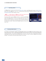
2-3. RACKMOUNT INFORMATION
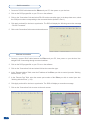
Tabletop mounting: The Eikos can be used directly on a table, the unit is equipped with 4 handy anti-slip
rubber feet.
Rack mounting: The Eikos is compatible with a 19” enclosure. Please follow the instructions below to install
the device in a 19” rack.
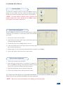
Place the device in your rack. Attach the device to the rack by using 4 screws through the front panel holes
(screws not included).
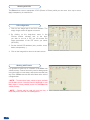
Rear xing is also recommended, in particular for permanent installations. The Eikos is equipped with drill
holes designed for compatibility with most rackmount braces.
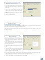
Connect all of the cables of the device and attach them to the rack with the help of tie wraps.
IMPORTANT:
- The openings in the side and rear panels of the device are for cooling. Do not cover these openings to
avoid cutting air circulation.
- Be sure that no weight in excess of 2 kg (4.4 Lbs.) is added onto the Eikos.
- The maximum ambient operating temperature should not exceed 40°C (104°F).
- The rack and all mounted equipment in it must be reliably grounded according to national and/or local
electrical standards.
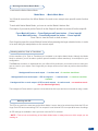
Dismantling front handles of the device could invalidate warranty on after sales services of your
Eikos. It is strongly advised to avoid using front handles as rests for your Eikos, they are designed
for manipulation purposes only.
If required, front handles of the device can be dismantled, but with caution. The original screws removed
must not be reintroduced to their location without handles in place. Substancial damages can occur,
including risk of electric shock from the main voltage. Only M4x12mm screws can be used. They are
supplied with the unit.
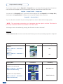
2-2. UNPACKING AND INSPECTION
1 x Eikos (EKS500)
1 x Power supply cord.
2 x DVI male to HD15 female and DVI-D female
Breakout Cable
1 x HD15-M to 5 BNC-F cable
1 x Ethernet cross cable (for device update)
1 x Set of 11 audio 5 pin screw terminals
1 x RCS - Remote Control Software (PC only) *
4 x Screws for handle removal (M4x12mm)
1 x User manual
1 x Quick Start guide
* Download on our website: www.analogway.com
2-4. CABLE AND ADAPTOR INFORMATION
A large choice of cables and adaptors are compatible with the Eikos. To nd which are to be used in your
setup, please refer to the Hardware Specications chapter. Please contact your distributor for a list of available
cables and connectors for your Eikos.
!
12
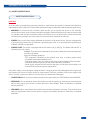
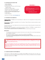
WARNING !
If required, front handles of the device can be dismantled,
but with caution.
The original screws removed must not be reintroduced to
their location without handles in place.
Substantial damages can occur, including risk of elec-
tric shock from the mains voltage.
Only M4x12mm screws can be used.
(They are supplied with the unit)

2-5. HARDWARE SPECIFICATIONS
13
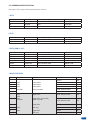
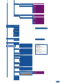
Description of the input formats supported by the device.
• SDTV
• EDTV
• HDTV (RGB or YUV)
Standard Size Frame Frequency Line Frequency
NTSC 525/480i 59.94Hz / 60Hz 15.735 KHz
PAL 625/576i 50Hz 15.625 KHz
SECAM 625/576i 50Hz 15.625 KHz
Standard Size Frame Frequency Line Frequency
480p 525/480i 59.94Hz / 60Hz 31.47 KHz
576p 625/576i 50Hz 31.25 KHz
Standard Size Frame Frequency Standard
720p 1280x720 50Hz / 59.94Hz / 60Hz SMPTE 296M
1035i 1920x1035 59.94Hz / 60Hz SMPTE 260M
1080i 1920x1080 50Hz / 59.94Hz / 60Hz SMPTE 274M
1080p 1920x1080 23.97Hz / 24Hz / 25Hz / 29.97Hz / 30Hz SMPTE 274M
1080sF 1920x1080 50Hz / 59.94Hz / 60Hz SMPTE 274M
1080p 1920x1080 50Hz / 60Hz HDTV
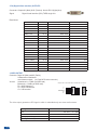
• INPUT FEATURES
Inputs Format Signal Connector EDID
1 HD15#1 YES
2 SDTV Analog SDTV HD15#2 YES
3 EDTV Analog EDTV HD15#3 NO
4 HDTV Analog HDTV HD15#4 NO
5 Computer Analog Computer DVI#1: ANALOG PART NO
6 DVI#2: ANALOG PART NO
7
SDTV
EDTV
HDTV
Computer
Digital SDTV (Except SDI)
Digital EDTV
Digital HDTV (Except SDI)
Digital Computer
DVI#1: DIGITAL PART YES
8
DVI#2: DIGITAL PART YES
9 Digital SDTV BNC#1 NO
10 SDTV
HDTV
(SDI only) BNC#2 NO
11 Digital HDTV BNC#3 NO
12 (SDI only) BNC#4 NO

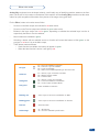
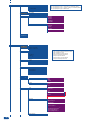
• EDID
SETTING AND INPUT FUNCTIONS
The EDID is available on inputs #1 & #2 and #7 & #8. The user can modify the EDID choosing from a list of
predened formats and frequencies.
Analog DVI-D SDI
Settings / Functions 1 2 3 4 5 6 7 8 9 10 11 12
Auto Settings
YES YES YES YES YES YES YES YES N/A N/A N/A N/A
Auto Framing
YES
1
YES
1
YES
1
YES
1
YES
1
YES
1
NO NO NO NO NO NO
Blanking Settings
YES YES YES YES YES YES NO NO NO NO NO NO
Cropping
YES YES YES YES YES YES YES YES YES YES YES YES
Optimization
YES
1
YES
1
YES
1
YES
1
YES
1
YES
1
NO NO NO NO NO NO
Under/Overscan
YES
2
YES
2
YES
2
YES
2
YES
2
YES
2
YES
2
YES
2
YES
2
YES
2
YES
2
YES
2
Aspect Ratio Settings
YES YES YES YES YES YES YES YES YES YES YES YES
Aspect Input Output
YES YES YES YES YES YES YES YES YES YES YES YES
Color Settings
YES YES YES YES YES YES YES YES YES YES YES YES
Advanced settings
YES YES YES YES YES YES NO NO NO NO NO NO
2:2 Pulldown
YES
3
YES
3
YES
3
YES
3
YES
3
YES
3
YES
3
YES
3
YES
3
YES
3
YES
3
YES
3
3:2 Pulldown
YES
4
YES
4
YES
4
YES
4
YES
4
YES
4
YES
4
YES
4
YES
4
YES
4
YES
4
YES
4
1/ Analog Computer Input or Analog Video Input (EDTV or HDTV only) 2/ Only Video Input
3/ Only interlaced 50 Hz 4/ Only interlaced 59.94 Hz to 60 Hz
14
• COMPUTER FORMATS
Format Size Reduced Blankings Subsampling
VGA 640x480
800x480 800x480
SVGA 800x600
WVGA 848x480
XGA 1024x768
1152x864 1152x864
1280x600 1280x600
720p RGB 1280x720
WXGA 1280x768
800p RGB 1280x800
960p RGB 1280x960
SXGA 1280x1024
SWXGA 1360x768
1360x1024 1360x1024
1366x768 1366x768
DILA4/3 1364x1024
SWXGA+ 1366x800
SXGA+ 1400x1050
900p RGB 1440x900
1600x900 1600x900
UXGA 1600x1200
WSXGA+ 1680x1050
1080p RGB 1920x1080 YES
WUXGA 1920x1200 YES
1920x1440 1920x1440 YES
2K 2048x1080 YES
QXGA 2048x1536 YES
The Eikos recognizes the following computer formats (Subsampled formats will be displayed with a degraded
quality. For a pixel clock > 165 MHz).

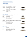
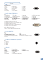
• RGB/S - RGsB VIDEO
Connectors: Inputs #1 to #4: female HD15. Inputs #5 & #6: female DVI-I (analog pins).
Frequency: 15.625 kHz - 50 Hz (625 lines).
15.734 kHz - 60 Hz (525 lines).
Levels: R, G, B = 0.7 Vp/p.
SYNC. = 0.3 Vp/p or TTL (negative).
Impedance: RGB = 75 ohms.
SYNC. = 75 ohms or Hi-Z.
• COMPONENT
Connectors: Inputs #1 to #4: female HD15. Inputs #5 & #6: female DVI-I (analog pins).
Input #8: female HD15.
Frequency: 15.625 kHz - 50 Hz (625 lines).
15.734 kHz - 60 Hz (525 lines).
Levels: Y = 1 Vp/p (0.7 V Luma + 0.3 V Sync.).
Cr / Pr & Cb / Pb = 0.7 Vp/p.
Impedance: 75 ohms.
• HDTV - HD-YUV
Connectors: Inputs #1 to #4: female HD15. Inputs #5 & #6: female DVI-I
(analog pins).
Formats: 720p/576p (60Hz), 1080i (50/60Hz), EDTV.
Levels: Y = 1 Vp/p (0.7 V + sync.).
Cr / Pr & Cb / Pb = 1 Vp/p (0.7 V + sync.).
Sync.: Tri-level: ±0.3V (positive/negative).
Bi-level: 0.3V (negative).
Impedance: 75 ohms.
or
or
or
Input specications
• ANALOG COMPUTER
Connectors: Inputs #1 to #4: female HD15. Inputs #5 & #6: female DVI-I
(analog pins).
Line frequency: Up to 130 kHz (165 MHz Max pixel rate).
Resolution: Up to 1600x1200 @ 165Mhz, 1920x1200px
(RB, Max V size: 1200px, Max H size 2048px).
Sync. types: RGBHV, RGB/S, RGsB (Sync On Green).
Levels: R, G, B = 0.7 Vp/p.
H & V Sync = TTL.
Composite Sync = TTL and 0.3 V (negative).
SOG (Sync On Green) = 0.3 V.
Impedance: R, G, B = 75 ohms.
H = 75 ohms or Hi-Z.
V = Hi-Z.
or
15

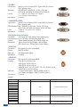
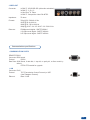
• AUDIO
• 3G/SD-SDI
Connector: SDI Inputs #1 to #4: female BNC.
Format: SMPTE 259M-C.
Data rate: 270 Mbps serial digital.
Impedance: 75 ohms.
• 3G/HD-SDI
Connector: SDI Inputs #1 to #4: female BNC.
Formats: 720p @ 50, 59.94 & 60 Hz.
1035i @ 50, 59.94 & 60 Hz.
1080i @ 50, 59.94 & 60 Hz.
1080p @ 23.97 / 24 / 25 / 29.97 / 30 / 50 / 59.94 & 60 Hz.
1080sF @ 50 / 59.94 & 60 Hz.
Data rate: 1.5 Gbps serial digital - SMPTE 292M (Level A).
2.97 Gbps serial digital - SMPTE 425M (Level A).
Impedance: 75 ohms.
• S.VIDEO
Connectors: Inputs #1 to #4: female HD15. Inputs #5 & #6: female
DVI-I (analog pins).
Standard: PAL/SECAM: 15.625 kHz - 50 Hz - 625 lines.
NTSC (3.58 - 4.43 MHz): 15.734 kHz / 60 Hz / 525 lines.
Levels: Y = 1 Vp/p (0.7 V Luma + 0.3 V Sync.).
C = 0.3 Vp/p (Chroma Burst).
Impedance: 75 ohms.
• COMPOSITE VIDEO
Connectors: Inputs #1 to #4: female HD15. Inputs #5 & #6: female
DVI-I (analog pins).
RCA.Standard: PAL / SECAM: 15.625 kHz - 50 Hz - 625 lines.
NTSC (3.58 - 4.43 MHz): 15.734 kHz / 60 Hz / 525 lines.
Level: 1 Vp/p (0.7 V Luma + 0.3 V Sync.).
Impedance: 75 ohms.
• DVI (Digital Video Interface)
Connector: DVI Inputs #1 & #2: female DVI-I (digital pins).
Line frequency: Up to 130 kHz (165 MHz Max pixel rate).
Format: Digital Visual Interface (DVI)-TMDS single link.
Resolution: Up to 1600x1200 @ 165Mhz, 1920x1200px.
(RB, Max V size: 1200px, Max H size 2048px).
or
or
16
Input# Stereo Balanced Audio Connectivity
1
YES
YES Connectors Phoenix 5 pins
2
3
4
5
6
7
8
9
Non applicable (Embedded Audio SDI) Non applicable (Embedded Audio SDI)
10
11
12
AUX
YES Connectors Phoenix 5 pins

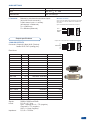
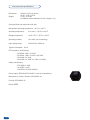
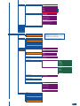
• ANALOG OUTPUTS
Connector: Outputs #1 (Main) & #2 (Preview):
female HD15, DVI-I (analog pins).
Resolutions:
Signals: RGBHV, RGBS and RGsB.
Levels: R, G, B = 0.7 Vp/p.
Sync. : Separate H & V = TTL (negative).
Composite = TTL (negative).
SOG = 0.3 Vp/p (negative).
Impedance: R, G, B = 75 ohms.
Output specications
Format Ratio Available Refresh Rates Reduced Blankings
640 x 480 4 : 3 50Hz 60Hz 72Hz 75Hz
800 x 600 4 : 3 50Hz 60Hz 72Hz 75Hz
848 x 480 16 : 9 50Hz 60Hz 72Hz 75Hz
1024 x 768 4 : 3 50Hz 60Hz 72Hz 75Hz
1280 x 720 16 : 9 50Hz 60Hz
1280 x 768 15 : 9 50Hz 60Hz 72Hz 75Hz
1280 x 800 16 : 10 50Hz 60Hz 72Hz 75Hz
1280 x 1024 5 : 4 50Hz 60Hz 72Hz 75Hz
1360 x 768 16 : 9 50Hz 60Hz 72Hz 75Hz
1366 x 800 15 : 9 50Hz 60Hz 72Hz 75Hz
1400 x 1050 4 : 3 50Hz 60Hz 72Hz 75Hz
1440 x 900 16 : 10 50Hz 60Hz 72Hz 75Hz
1600 x 1200 4 : 3 50Hz 60Hz
1680 x 1050 16 : 10 50Hz 60Hz
1920 x 1080 16 : 9 50Hz 60Hz 72Hz 75Hz YES
1920 x 1080 B 16 : 9 50Hz 60Hz YES
1920 x 1080 C 16:9 50Hz 60Hz YES
1920 x 1080 HD 16:9 50Hz 60Hz YES
1920 x 1200 16 : 10 50Hz 60Hz YES
2048 x 1080 19 : 10 50Hz 60Hz YES
or
• Connector: Balanced or unbalanced mono/stereo inputs
(all pin MCO male connector).
8 audio stereo inputs + 1 auxiliary.
(all balanced / unbalanced).
Vi = +15dBV max.
Zi = 40Kohms (Balanced).
L+
L-
R+
R-
UNBALANCED
LEFT
RIGHT
GROUND
4
MCO male connectors
Inputs #1 to #6: Balanced & unbalanced connection
Inputs DVI #1 to DVI #2: Balanced & unbalanced
connection
Input AUX: Balanced & unbalanced connection
17
AUDIO SETTINGS
Settings Availability
GAIN
YES: from -
∞
to + 18dB
Balanced Audio YES: Left and Right
4
L+
L-
R+
R-
BALANCED
L+
R+
L-
R-
GROUND(S)
Outputs #1 to #2: Balanced & unbalanced connection

• DVI (Digital Video Interface) OUTPUTS
Connector: Outputs #1 (Main) & #2 (Preview): female DVI-I (digital pins).
Signal: Digital Visual Interface (DVI)-TMDS single link.
Resolutions:
Format Ratio Refresh Rate Reduced Blanking
640 x 480 4 : 3 50Hz 60Hz 72Hz 75Hz
800 x 600 4 : 3 50Hz 60Hz 72Hz 75Hz
848 x 480 16 : 9 50Hz 60Hz 72Hz 75Hz
1024 x 768 4 : 3 50Hz 60Hz 72Hz 75Hz
1280 x 720 16 : 9 50Hz 60Hz
1280 x 768 15 : 9 50Hz 60Hz 72Hz 75Hz
1280 x 800 16 : 10 50Hz 60Hz 72Hz 75Hz
1280 x 1024 5 : 4 50Hz 60Hz 72Hz 75Hz
1360 x 768 16 : 9 50Hz 60Hz 72Hz 75Hz
1366 x 800 15 : 9 50Hz 60Hz 72Hz 75Hz
1400 x 1050 4 : 3 50Hz 60Hz 72Hz 75Hz
1440 x 900 16 : 10 50Hz 60Hz 72Hz 75Hz
1600 x 1200 4 : 3 50Hz 60Hz
1680 x 1050 16 : 10 50Hz 60Hz
1920 x 1080 16 : 9 50Hz 60Hz 72Hz 75Hz YES
1920 x 1080 B 16 : 9 50Hz 60Hz YES
1920 x 1080C 16 : 9 50Hz 60Hz YES
1920 x 1080 HD 16 : 9 50Hz 60Hz YES
1920 x 1200 16 : 10 50Hz 60Hz YES
2048 x 1080 19 : 10 50Hz 60Hz YES
• AUDIO OUTPUT
Connector: Output #1 (Main) and #2 (Prelist):
2 Balanced or unbalanced.
mono/stereo outputs (on 5-pin MCO male connector).
Vo max: Unbalanced = +15dBu (at 300Ω load).
Balanced = +21dBu (at 600Ω load).
Zo = 600Ω balanced.
Zo = 300Ω unbalanced.
G = 0 dB nominal.
4
L+
L-
R+
R-
BALANCED
L+
R+
L-
R-
GROUND(S)
Outputs #1 to #2: Balanced & unbalanced connection
The video output generates a SDI signal in which is embedded only one stereo audio stream.
18
Settings Availability
Gain
Yes: from -
∞
to +18dB
Balanced Audio Left and Right
Auxiliary Input Mixing Yes
Adjusting Audio Delay Yes: from 0 to 80ms (Automatic or Manual)
La pagina si sta caricando...
La pagina si sta caricando...
La pagina si sta caricando...
La pagina si sta caricando...
La pagina si sta caricando...
La pagina si sta caricando...
La pagina si sta caricando...
La pagina si sta caricando...
La pagina si sta caricando...
La pagina si sta caricando...
La pagina si sta caricando...
La pagina si sta caricando...
La pagina si sta caricando...
La pagina si sta caricando...
La pagina si sta caricando...
La pagina si sta caricando...
La pagina si sta caricando...
La pagina si sta caricando...
La pagina si sta caricando...
La pagina si sta caricando...
La pagina si sta caricando...
La pagina si sta caricando...
La pagina si sta caricando...
La pagina si sta caricando...
La pagina si sta caricando...
La pagina si sta caricando...
La pagina si sta caricando...
La pagina si sta caricando...
La pagina si sta caricando...
La pagina si sta caricando...
La pagina si sta caricando...
La pagina si sta caricando...
La pagina si sta caricando...
La pagina si sta caricando...
La pagina si sta caricando...
La pagina si sta caricando...
La pagina si sta caricando...
La pagina si sta caricando...
La pagina si sta caricando...
La pagina si sta caricando...
La pagina si sta caricando...
La pagina si sta caricando...
La pagina si sta caricando...
La pagina si sta caricando...
La pagina si sta caricando...
La pagina si sta caricando...
La pagina si sta caricando...
La pagina si sta caricando...
La pagina si sta caricando...
La pagina si sta caricando...
La pagina si sta caricando...
La pagina si sta caricando...
La pagina si sta caricando...
La pagina si sta caricando...
La pagina si sta caricando...
La pagina si sta caricando...
La pagina si sta caricando...
La pagina si sta caricando...
La pagina si sta caricando...
La pagina si sta caricando...
La pagina si sta caricando...
La pagina si sta caricando...
La pagina si sta caricando...
La pagina si sta caricando...
La pagina si sta caricando...
La pagina si sta caricando...
La pagina si sta caricando...
La pagina si sta caricando...
La pagina si sta caricando...
La pagina si sta caricando...
La pagina si sta caricando...
La pagina si sta caricando...
-
 1
1
-
 2
2
-
 3
3
-
 4
4
-
 5
5
-
 6
6
-
 7
7
-
 8
8
-
 9
9
-
 10
10
-
 11
11
-
 12
12
-
 13
13
-
 14
14
-
 15
15
-
 16
16
-
 17
17
-
 18
18
-
 19
19
-
 20
20
-
 21
21
-
 22
22
-
 23
23
-
 24
24
-
 25
25
-
 26
26
-
 27
27
-
 28
28
-
 29
29
-
 30
30
-
 31
31
-
 32
32
-
 33
33
-
 34
34
-
 35
35
-
 36
36
-
 37
37
-
 38
38
-
 39
39
-
 40
40
-
 41
41
-
 42
42
-
 43
43
-
 44
44
-
 45
45
-
 46
46
-
 47
47
-
 48
48
-
 49
49
-
 50
50
-
 51
51
-
 52
52
-
 53
53
-
 54
54
-
 55
55
-
 56
56
-
 57
57
-
 58
58
-
 59
59
-
 60
60
-
 61
61
-
 62
62
-
 63
63
-
 64
64
-
 65
65
-
 66
66
-
 67
67
-
 68
68
-
 69
69
-
 70
70
-
 71
71
-
 72
72
-
 73
73
-
 74
74
-
 75
75
-
 76
76
-
 77
77
-
 78
78
-
 79
79
-
 80
80
-
 81
81
-
 82
82
-
 83
83
-
 84
84
-
 85
85
-
 86
86
-
 87
87
-
 88
88
-
 89
89
-
 90
90
-
 91
91
-
 92
92


Analog way Eikos Manuale utente
- Categoria
- Convertitori video
- Tipo
- Manuale utente
- Questo manuale è adatto anche per
in altre lingue
- English: Analog way Eikos User manual
Documenti correlati
-
Analog way Smart MatriX SMX200 Manuale utente
-
-
-
-
-
-
-
-
-
Altri documenti
-
Sylvania SLED5516A Manuale del proprietario
-
Lindy 38135 Manuale utente
-
-
NDS Radiance Manuale del proprietario
-
Barco X-Port 3G-SDI Guida Rapida
-
Sony VPH-G70QM Operating Instructions Manual
-
-
JVC Music Mixer KM-H3000E Manuale utente
-
Barco AMM240ED Guida utente
-