Asus RS500A-E12-RS4U Manuale utente
- Categoria
- Schede madri
- Tipo
- Manuale utente

1U Rackmount Server
User Guide
RS500A-E12 Series
RS500A-E12-RS4U

ii
Copyright © 2023 ASUSTeK COMPUTER INC. All Rights Reserved.
No part of this manual, including the products and software described in it, may be reproduced, transmitted,
transcribed, stored in a retrieval system, or translated into any language in any form or by any means,
except documentation kept by the purchaser for backup purposes, without the express written permission
of ASUSTeK COMPUTER INC. (“ASUS”).
ASUS provides this manual “as is” without warranty of any kind, either express or implied, including but not
limited to the implied warranties or conditions of merchantability or fitness for a particular purpose. In no
event shall ASUS, its directors, officers, employees, or agents be liable for any indirect, special, incidental,
or consequential damages (including damages for loss of profits, loss of business, loss of use or data,
interruption of business and the like), even if ASUS has been advised of the possibility of such damages
arising from any defect or error in this manual or product.
Specifications and information contained in this manual are furnished for informational use only, and are
subject to change at any time without notice, and should not be construed as a commitment by ASUS.
ASUS assumes no responsibility or liability for any errors or inaccuracies that may appear in this manual,
including the products and software described in it.
Product warranty or service will not be extended if: (1) the product is repaired, modified or altered, unless
such repair, modification of alteration is authorized in writing by ASUS; or (2) the serial number of the
product is defaced or missing.
Products and corporate names appearing in this manual may or may not be registered trademarks or
copyrights of their respective companies, and are used only for identification or explanation and to the
owners’ benefit, without intent to infringe.
E21984
Revised Edition V3
June 2023

iii
Contents
Safety information ..................................................................................................... vii
About this guide ......................................................................................................... xi
Chapter 1: Product Introduction
1.1 System package contents ......................................................................... 1-2
1.2 Serial number label .................................................................................... 1-3
1.3 System specifications ...............................................................................1-4
1.4 Front panel features ...................................................................................1-6
1.5 Rear panel features ....................................................................................1-7
1.6 Internal features .........................................................................................1-8
1.7 LED information .........................................................................................1-9
1.7.1 Front panel LEDs ........................................................................ 1-9
1.7.2 Storage device status LEDs ...................................................... 1-10
1.7.3 Rear panel LEDs ....................................................................... 1-10
1.7.4 LAN (RJ45) LEDs...................................................................... 1-11
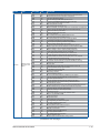
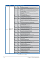
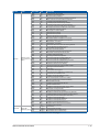
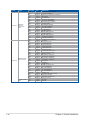
1.7.5 Q-Code table ............................................................................. 1-12
Chapter 2: Hardware Information
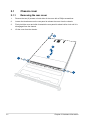
2.1 Chassis cover .............................................................................................2-2
2.1.1 Removing the rear cover ............................................................. 2-2
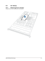
2.2 Air duct(s) ...................................................................................................2-3
2.2.1 Removing the air duct(s) ............................................................. 2-3
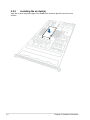
2.2.2 Installing the air duct(s) ............................................................... 2-4
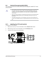
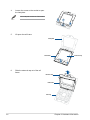
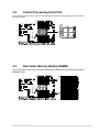
2.3 Central Processing Unit (CPU) .................................................................2-5
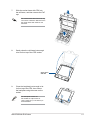
2.3.1 Installing the CPU and heatsink .................................................. 2-5
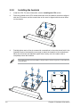
2.3.2 Installing the heatsink..................................................................2-8
2.4 System memory .......................................................................................2-10
2.4.1 Overview ................................................................................... 2-10
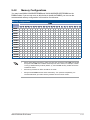
2.4.2 Memory Configurations ............................................................. 2-11
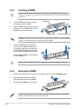
2.4.3 Installing a DIMM ...................................................................... 2-12
2.4.4 Removing a DIMM .................................................................... 2-12
2.5 (optional) Front bezel ...............................................................................2-13
2.5.1 Removing the front bezel .......................................................... 2-13
2.5.2 Installing the front bezel ............................................................ 2-14
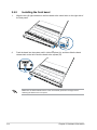
2.6 Storage devices........................................................................................2-15

iv
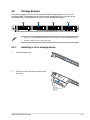
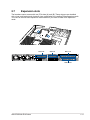
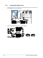
2.7 Expansion slots ........................................................................................2-17
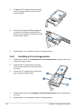
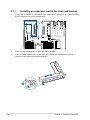
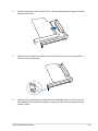
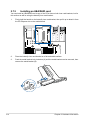
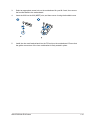
2.7.1 Installing an expansion card to the riser card bracket ............... 2-18
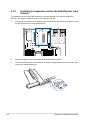
2.7.2 Installing an expansion card to the butterfly riser card bracket . 2-20
2.7.3 Installing an HBA/RAID card ..................................................... 2-22
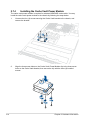
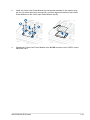
2.7.4 Installing the Cache Vault Power Module ................................. 2-24
2.7.5 Installing M.2 (NGFF) cards ...................................................... 2-26
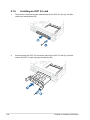
2.7.6 Installing an OCP 3.0 card ........................................................ 2-28
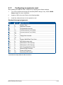
2.7.7 Configuring an expansion card ................................................. 2-29
2.8 Cable connections ...................................................................................2-30
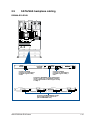
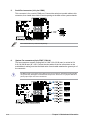
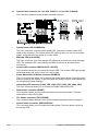
2.9 SATA/SAS backplane cabling .................................................................2-31
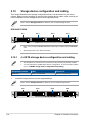
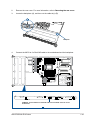
2.10 Storage device configuration and cabling ............................................2-32
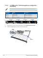
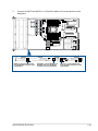
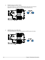
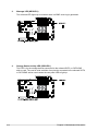
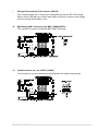
2.10.1 4 x SATA storage device configuration and cabling ................. 2-32
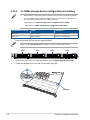
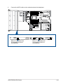
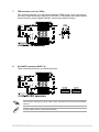
2.10.2 4 x NVMe storage device configuration and cabling ................. 2-34
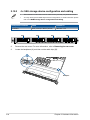
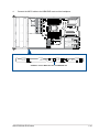
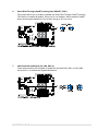
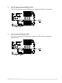
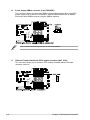
2.10.3 4 x SAS storage device configuration and cabling .................... 2-36
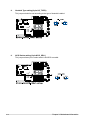
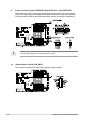
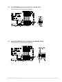
2.10.4 4 x NVMe and 4 x SATA storage device configuration and
cabling ....................................................................................... 2-38
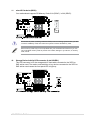
2.11 Optional components ..............................................................................2-40
2.12 Rail Kit Options ........................................................................................2-42
Chapter 3: Motherboard Information
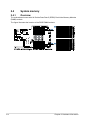
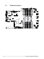
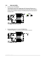
3.1 Motherboard layout ....................................................................................3-2
3.2 Central Processing Unit (CPU) .................................................................3-5
3.3 Dual Inline Memory Module (DIMM) ..........................................................3-5
3.4 Jumpers ......................................................................................................3-6
3.5 Internal LEDs ............................................................................................ 3-11
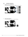
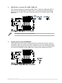
3.6 Internal connectors ..................................................................................3-14
Chapter 4: BIOS Setup
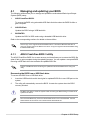
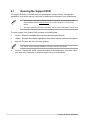
4.1 Managing and updating your BIOS ..........................................................4-2
4.1.1 ASUS CrashFree BIOS 3 utility................................................... 4-2
4.1.2 ASUS EZ Flash Utility ................................................................. 4-3
4.1.3 BUPDATER utility ....................................................................... 4-4
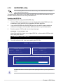
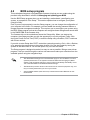
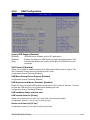
4.2 BIOS setup program ..................................................................................4-6
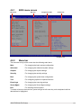
4.2.1 BIOS menu screen ...................................................................... 4-7
4.2.2 Menu bar ..................................................................................... 4-7
4.2.3 Menu items..................................................................................4-8
4.2.4 Submenu items ........................................................................... 4-8
4.2.5 Navigation keys ........................................................................... 4-8
4.2.6 General help................................................................................4-8
4.2.7 Configuration fields ..................................................................... 4-8

v
4.2.8 Pop-up window............................................................................4-8
4.2.9 Scroll bar ..................................................................................... 4-8
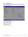
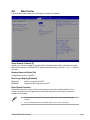
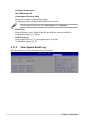
4.3 Main menu ..................................................................................................4-9
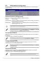
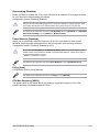
4.4 Performance Tuning menu ......................................................................4-10
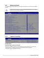
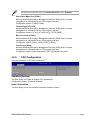
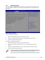
4.5 Advanced menu .......................................................................................4-12
4.5.1 Trusted Computing.................................................................... 4-12
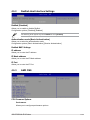
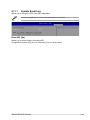
4.5.2 Redfish Host Interface Settings................................................. 4-13
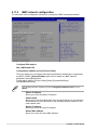
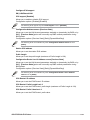
4.5.3 AMD CBS .................................................................................. 4-13
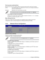
4.5.4 Onboard LAN Configuration ...................................................... 4-22
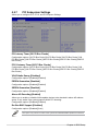
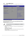
4.5.5 Serial Port Console Redirection ................................................ 4-23
4.5.6 CPU Configuration .................................................................... 4-25
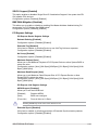
4.5.7 PCI Subsystem Settings ........................................................... 4-26
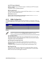
4.5.8 USB Configuration .................................................................... 4-31
4.5.9 Network Stack Configuration..................................................... 4-32
4.5.10 NVMe Configuration .................................................................. 4-33
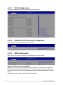
4.5.11 SATA Configuration .................................................................. 4-34
4.5.12 Offboard SATA Controller Configuration ................................... 4-34
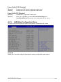
4.5.13 APM Configuration .................................................................... 4-34
4.5.14 AMD Mem Configuration Status................................................ 4-35
4.5.15 T1s Auth .................................................................................... 4-36
4.5.16 Driver Health ............................................................................. 4-36
4.5.17 Third-party UEFI driver configurations ...................................... 4-37
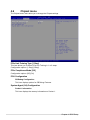
4.6 Chipset menu ...........................................................................................4-38
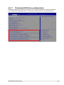
4.7 Security menu ..........................................................................................4-39
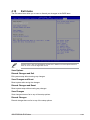
4.8 Boot menu ................................................................................................4-43
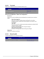
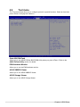
4.9 Tool menu ................................................................................................. 4-44
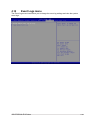
4.10 Event Logs menu .....................................................................................4-45
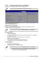
4.10.1 Change Smbios Event Log Settings ......................................... 4-46
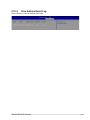
4.10.2 View Smbios Event Log ............................................................ 4-47
4.11 Server Mgmt menu ...................................................................................4-48
4.11.1 System Event Log ..................................................................... 4-49
4.11.2 BMC network configuration ....................................................... 4-50
4.11.3 View System Event Log ............................................................ 4-52
4.12 Exit menu .................................................................................................. 4-53
Chapter 5: Driver Installation
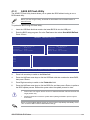
5.1 Running the Support DVD .........................................................................5-2

vi
Appendix
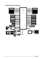
K14PA-U24 block diagram ..................................................................................... A-2
Notices .................................................................................................................... A-3
Service and Support ............................................................................................... A-7

vii
Safety information
Electrical Safety
• Before installing or removing signal cables, ensure that the power cables for the system
unit and all attached devices are unplugged.
• To prevent electrical shock hazard, disconnect the power cable from the electrical
outlet before relocating the system.
• When adding or removing any additional devices to or from the system, ensure that the
power cables for the devices are unplugged before the signal cables are connected.
If possible, disconnect all power cables from the existing system before you add a
device.
• If the power supply is broken, do not try to fix it by yourself. Contact a qualified service
technician or your dealer.
Sécurité électrique
• Avant d’installer ou de retirer des câbles, assurez-vous que les câbles d’alimentation du
système et de tous les périphériques sont débranchés.
• Pour éviter tout risque de choc électrique, débranchez le câble d’alimentation de la prise
électrique avant de toucher au système.
• Lors de l’ajout ou du retrait de périphériques, vérifiez que les câbles d’alimentation sont
débranchés avant de brancher d’autres câbles. Si possible, déconnectez tous les câbles
d’alimentation du système avant d’y installer un périphérique.
• Si le bloc d’alimentation est endommagé, n’essayez pas de le réparer vous-même. Contactez
un technicien électrique qualifié ou votre revendeur.

viii
Operation Safety
• Any mechanical operation on this server must be conducted by certified or experienced
engineers.
• Before operating the server, carefully read all the manuals included with the server
package.
• Before using the server, ensure all cables are correctly connected and the power
cables are not damaged. If any damage is detected, contact your dealer as soon as
possible.
• To avoid short circuits, keep paper clips, screws, and staples away from connectors,
slots, sockets and circuitry.
• Avoid dust, humidity, and temperature extremes. Place the server on a stable surface.
• If you encounter technical problems with the product, contact a qualified service
technician or your retailer.
This product is equipped with a three-wire power cable and plug for the user’s safety. Use
the power cable with a properly grounded electrical outlet to avoid electrical shock.
Sécurité de fonctionnement
• Toute opération mécanique sur ce serveur doit être effectuée par des ingénieurs certifiés ou
expérimentés.
• Avant d'utiliser le serveur, lisez attentivement tous les manuels fournis avec ce dernier.
• Avant d'utiliser le serveur, vérifiez que tous les câbles sont bien branchés et que les câbles
d'alimentation ne sont pas endommagés. Si des dommages sont détectés, contactez votre
revendeur dès que possible.
• Pour éviter les court-circuits, gardez les clips, les vis et les agrafes loin des connecteurs, des
slots, des interfaces de connexion et de la circuiterie.
• Évitez la poussière, l'humidité et les températures extrêmes. Placez le serveur sur une surface
stable.
• Si vous rencontrez des problèmes techniques avec votre produit, contactez un technicien
qualifié ou votre revendeur.
Ce produit est équipé d’un câble d’alimentation et d’une prise tripolaires pour la sécurité de
l’utilisateur. Utilisez le câble d’alimentation sur une prise électrique correctement reliée à la
terre pour éviter les chocs électriques.

ix
Heavy System
CAUTION! This server system is heavy. Ask for assistance when moving
or carrying the system.
Lithium-Ion Battery Warning
CAUTION! Danger of explosion if battery is incorrectly replaced. Replace
only with the same or equivalent type recommended by the manufacturer.
Dispose of used batteries according to the manufacturer’s instructions.
Restricted Access Location
This product is intended for installation only in a Computer Room where:
• Access can only be gained by SERVICE PERSONS or by USERS who have been
instructed about the reasons for the restrictions applied to the location and about any
precautions that shall be taken.
• Access is through the use of a TOOL, or other means of security, and is controlled by
the authority responsible for the location.
Emplacement d’accès restreint
Ce produit est destiné à être installé uniquement dans une salle informatique où :
• L’accès est uniquement accordé aux TECHNICIENS ou UTILISATEURS qui ont connaissance des
raisons de cette restriction et des précautions qui devraient être prises.
• L’accès se fait par le biais d’un OUTIL ou tout dispositif de sécurité, et est contrôlé par l’autorité
responsable de cet emplacement.
Système lourd
ATTENTION ! Ce serveur est un système lourd. Demandez de l'aide pour
déplacer ou transporter le système.
Avertissement sur les batteries Lithium-Ion
ATTENTION ! Danger d'explosion si la batterie n'est pas correctement
remplacée. Remplacer uniquement par une batterie de type identique ou
équivalent, comme recommandé par le fabricant. Jetez les batteries usagées
conformément aux instructions du fabricant.

x
To prevent exposure to the optical drive’s laser, do not attempt to disassemble or repair the
optical drive by yourself. For your safety, contact a professional technician for assistance.
CLASS 1 LASER PRODUCT
Optical Drive Safety Information
Laser Safety Information
Risque d'exposition dangereuse au laser. Ne tentez pas de démonter ou réparer le
lecteur de disque optique. Pour votre sécurité, faites réparer le lecteur de disque optique
uniquement par un prestataire de dépannage agréé.
Informations de sécurité concernant le lecteur optique
Informations de sécurité relatives au laser
PRODUIT LASER DE CLASSE 1

xi
About this guide
Audience
This user guide is intended for system integrators, and experienced users with at least basic
knowledge of configuring a server.
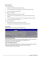
Contents
This guide contains the following parts:
1. Chapter 1: Product Introduction
This chapter describes the general features of the server, including sections on front
panel and rear panel specifications.
2. Chapter 2: Hardware Information
This chapter lists the hardware setup procedures that you have to perform when
installing or removing system components.
3. Chapter 3: Installation Options
This chapter describes how to install optional components into the barebone server.
4. Chapter 4: Motherboard Information
This chapter gives information about the motherboard that comes with the server. This
chapter includes the motherboard layout, jumper settings, and connector locations.
5. Chapter 5: BIOS Setup
This chapter tells how to change system settings through the BIOS Setup menus and
describes the BIOS parameters.
6. Chapter 6: Driver Installation
This chapter provides instructions for installing the necessary drivers for different
system components.

xii
References
Refer to the following sources for additional information and for product and software updates.
1. ASUS Control Center (ACC) user guide
This manual tells how to set up and use the proprietary ASUS server management
utility. Visit asuscontrolcenter.asus.com for more information.
2. ASUS websites
The ASUS websites provide updated information for all ASUS hardware and software
products. Visit https://www.asus.com for more information.
Conventions
To ensure that you perform certain tasks properly, take note of the following symbols used
throughout this manual.
Typography
Bold text Indicates a menu or an item to select.
Italics
Used to emphasize a word or a phrase.
<Key> Keys enclosed in the less-than and greater-than sign
means that you must press the enclosed key.
Example: <Enter> means that you must press the Enter
or Return key.
<Key1>+<Key2>+<Key3> If you must press two or more keys simultaneously, the
key names are linked with a plus sign (+).
Example: <Ctrl>+<Alt>+<Del>
Command Means that you must type the command exactly as
shown, then supply the required item or value enclosed in
brackets.
Example: At the DOS prompt, type the command line:
format A:/S
DANGER/WARNING: Information to prevent injury to yourself when trying to
complete a task.
CAUTION: Information to prevent damage to the components when
trying to complete a task.
IMPORTANT: Instructions that you MUST follow to complete a task.
NOTE: Tips and additional information to help you complete a task.

This chapter describes the general features of the server. It
includes sections on front panel and rear panel specifications.
1
Product Introduction
Chapter 1: Product Introduction

Chapter 1: Product Introduction
1-2
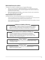
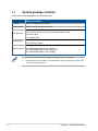
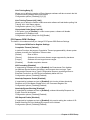
1.1 System package contents
Check your system package for the following items.
RS500A-E12-RS4U
Chassis ASUS 1U Rackmount Chassis
Motherboard ASUS K14PA-U24 Server Board
Components
1 x Storage Device Backplane
4 x Hot-swap 3.5-inch or 2.5-inch Storage Device Trays
2 x Riser Cards
7 x System Fans
Accessories 1 x CPU Heatsink
2 x AC Power Cables
Optional Items
1 x Friction Rail Kit or 1 x Ball Bearing Rail Kit
2 x 800W Redundant Power Supply or
2 x 1200W Redundant Power Supply or
2 x 1600W Redundant Power Supply
• If any of the above items is damaged or missing, contact your retailer.
• Optional items come bundled if you selected them when purchasing the system and
cannot be bought separately.

ASUS RS500A-E12 Series 1-3
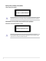
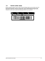
1.2 Serial number label
Before requesting support from the ASUS Technical Support team, you must take note of the
product’s serial number containing 12 characters, such as xxSxxxxxxxxx, as shown in the
figure below. With the correct serial number of the product, ASUS Technical Support team
members can then offer a quicker and satisfying solution to your problems.
xxSxxxxxxxxx
RS500A-E12-RS4U
1234

Chapter 1: Product Introduction
1-4
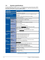
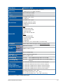
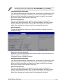
1.3 System specifications
The ASUS RS500A-E12-RS4U server is a 1U barebone server system featuring the ASUS
K14PA-U24 Server Board. The server supports AMD EPYC™ 9004 Series processors plus
other latest technologies through the chipsets onboard.
Model Name RS500A-E12-RS4U
Motherboard K14PA-U24
Processor Support
1 x Socket SP5 (LGA-6096)
4th Genenration AMD EPYC™ processors with AMD 3D V-Cache
technology
AMD EPYC™ 9004 series processors (up to 400W)
Core Logic System on Chip (SoC)
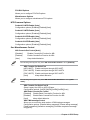
Memory
Total Slots 24 (12 channels per CPU, 2 DIMMs per channel*)
* 2DPC support depends on AMD schedule
Capacity Maximum 6144GB
Memory Type
DDR5 4800/4400/4000/3600 RDIMM/ 3DS RDIMM
1 DPC up to 4800
2 DPC up to 4000 (1R+1R)
2 DPC up to 3600 (1R+2R)/(2R+2R)
* Please refer to www.asus.com for latest momory AVL update
Memory Size
256GB,128GB, 64GB, 32GB RDIMM
256GB,128GB, 64GB, 32GB 3DS RDIMM
* Refer to www.asus.com for the latest memory AVL update.
Expansion
Slots
Total PCI/
PCI-X/PCI-E
Slots
3+1
Slot Type
1 x PCIe x16 slot (Gen5 x16 link, FH, HL)
1 x PCIe x16 slot (Gen5 x16 link, LP, HL)
1 x PCIe x16 slot (Gen5 x8 link, LP, HL)
1 x OCP3.0 socket (Gen5 x16 link)
Disk
Controller
SATA
Controller
CPU Integrated
2 x M.2 connectors (SATA3 6Gb/s & PCIe Gen5 x4 link)
1 x SATA controller (SATA3 6Gb/s)
SAS Controller Optional kit(s):
ASUS PIKE II 3008 8-port SAS 12Gb/s HBA card
Storage
Bays
4 x 3.5”/2.5” Hot-swap Storage Bays
(backplane supports 4 x SATA/SAS*/NVMe)
* SAS support only from optional SAS HBA/RAID card.
Backplane
connectors
2 x MCIO x2 (for NVMe)
1 x SlimSAS x4 (for SATA)
Motherboard
onboard
connectors
2 x M.2 connectors
8 x SlimSAS connectors
(continued on the next page)

ASUS RS500A-E12 Series 1-5
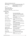
Model Name RS500A-E12-RS4U
Networking 1 x Dual Port Intel® I350 Gigabit LAN Controller
1 x Management Port (BMC, AST2600)
VGA Aspeed AST2600 256MB
Graphic Up to 2 single-wide GPU
Front I/O Ports 2 x USB 3.2 Gen 1 ports
1 x VGA port
Rear I/O Ports
2 x USB 3.2 Gen 1 ports
2 x Gigabit LAN ports (RJ45)
1 x Management port (RJ45)
1 x VGA port
Switch/LED
Rear:
1 x Power Button/LED
1 x Location Button/LED
1 x Message LED
1 x Q-Code (Port 80) LED
Front:
1 x Power Button/LED
1 x Location Button/LED
1 x Message LED
1 x HDD LED
4 x LAN LED (1-2 for onboard LAN; 3-4 for OCP LAN)
OS Support Please find the latest OS support from http://www.asus.com/
Management
Solution
Software ASUS Control Center
Out of Band
Remote
Management
ASMB11-iKVM (on-board)
Regulatory Compliance CE, FCC, BSMI, RCM
Dimension
(HH x WW x DD)
843mm x 449mm x 44mm (1U)
33.17” x 17.68” x 1.73”
Net Weight Kg 13.15 Kg (CPU, DRAM & Storage device not included)
Gross Weight Kg 18.15 Kg (CPU, DRAM & Storage device not included, Packing
included)
Power Supply
(following different
configuration by region)
1+1 Redundant 800W 80 PLUS Platinum Power Supply or
1+1 Redundant 800W 80 PLUS Titanium Power Supply or
1+1 Redundant 1200W 80 PLUS Platinum Power Supply or
1+1 Redundant 1600W 80 PLUS Platinum Power Supply or
1+1 Redundant 1600W 80 PLUS Titanium Power Supply
Environment
Operating temperature: 10°C ~ 35°C
Non-operating temperature: -40°C ~ 60°C
Non-operating humidity: 20% ~ 90% ( Non-condensing)
*Specifications are subject to change without notice.

Chapter 1: Product Introduction
1-6
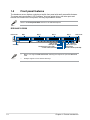
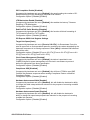
1.4 Front panel features
The barebone server displays a simple yet stylish front panel with easily accessible features.
The power and reset buttons, LED indicators, slim type optical drive, and other ports and
buttons are located on the front panel, this may vary between models.
Refer to the Front panel LEDs section for the LED descriptions.
RS500A-E12-RS4U
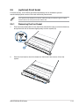
• Bays 1 to 4 support NVMe/SATA/SAS. SAS support requires an optional HBA/RAID
card.
• All bays support 3.5”/2.5” drives with trays.
1234
Rack screw Bay 1 Bay 2 Bay 3 Bay 4 Rack screw
VGA port
USB 3.2 Gen 1 port
Reset button
Location button (with LED)Power button (with LED)
Storage device access LED
Message LED
LAN 1-4 LED
Asset tag

ASUS RS500A-E12 Series 1-7
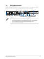
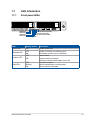
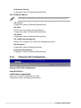
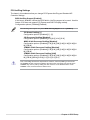
1.5 Rear panel features
The rear panel includes expansion slots and system power socket. The middle part includes
the I/O shield with openings for the rear panel connectors on the motherboard.
• Management LAN port is for ASUS ASMB11-iKVM only.
• The Q-Code LED provides the most probable cause of an error code as a starting
point for troubleshooting. The actual cause may vary from case to case.
• Refer to the Q-Code table for details.
Q-Code LED
Expansion slot Expansion slot Expansion slot
OCP 3.0 slot
Power button with LED
VGA port
Location button with LED
Redundant Power supply
and Power cord connector
USB 3.2 Gen 1 ports
Management LAN port
LAN port 1
LAN port 2

Chapter 1: Product Introduction
1-8
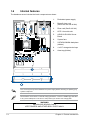
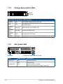
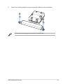
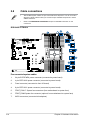
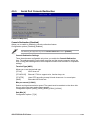
1.6 Internal features
The barebone server includes the basic components as shown.
The barebone server does not include a floppy disk drive. Connect a USB floppy disk drive
to any of the USB ports on the front or rear panel if you need to use a floppy disk.
WARNING
HAZARDOUS MOVING PARTS
KEEP FINGERS AND OTHER BODY PARTS AWAY
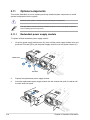
1. Redundant power supply
2. Butterfly riser card
(Gen5 x16 link and x8 link)
3. Riser card (Gen5 x16 link)
4. OCP 3.0 module slot
5. ASUS K14PA-U24 Server
Board
6. System fans
7. SATA/SAS/NVMe backplane
(hidden)
8. 4 x 3.5” storage device bays
9. Asset tag (hidden)
Turn off the system power and detach the power supply before removing or replacing any
system component.
La pagina si sta caricando...
La pagina si sta caricando...
La pagina si sta caricando...
La pagina si sta caricando...
La pagina si sta caricando...
La pagina si sta caricando...
La pagina si sta caricando...
La pagina si sta caricando...
La pagina si sta caricando...
La pagina si sta caricando...
La pagina si sta caricando...
La pagina si sta caricando...
La pagina si sta caricando...
La pagina si sta caricando...
La pagina si sta caricando...
La pagina si sta caricando...
La pagina si sta caricando...
La pagina si sta caricando...
La pagina si sta caricando...
La pagina si sta caricando...
La pagina si sta caricando...
La pagina si sta caricando...
La pagina si sta caricando...
La pagina si sta caricando...
La pagina si sta caricando...
La pagina si sta caricando...
La pagina si sta caricando...
La pagina si sta caricando...
La pagina si sta caricando...
La pagina si sta caricando...
La pagina si sta caricando...
La pagina si sta caricando...
La pagina si sta caricando...
La pagina si sta caricando...
La pagina si sta caricando...
La pagina si sta caricando...
La pagina si sta caricando...
La pagina si sta caricando...
La pagina si sta caricando...
La pagina si sta caricando...
La pagina si sta caricando...
La pagina si sta caricando...
La pagina si sta caricando...
La pagina si sta caricando...
La pagina si sta caricando...
La pagina si sta caricando...
La pagina si sta caricando...
La pagina si sta caricando...
La pagina si sta caricando...
La pagina si sta caricando...
La pagina si sta caricando...
La pagina si sta caricando...
La pagina si sta caricando...
La pagina si sta caricando...
La pagina si sta caricando...
La pagina si sta caricando...
La pagina si sta caricando...
La pagina si sta caricando...
La pagina si sta caricando...
La pagina si sta caricando...
La pagina si sta caricando...
La pagina si sta caricando...
La pagina si sta caricando...
La pagina si sta caricando...
La pagina si sta caricando...
La pagina si sta caricando...
La pagina si sta caricando...
La pagina si sta caricando...
La pagina si sta caricando...
La pagina si sta caricando...
La pagina si sta caricando...
La pagina si sta caricando...
La pagina si sta caricando...
La pagina si sta caricando...
La pagina si sta caricando...
La pagina si sta caricando...
La pagina si sta caricando...
La pagina si sta caricando...
La pagina si sta caricando...
La pagina si sta caricando...
La pagina si sta caricando...
La pagina si sta caricando...
La pagina si sta caricando...
La pagina si sta caricando...
La pagina si sta caricando...
La pagina si sta caricando...
La pagina si sta caricando...
La pagina si sta caricando...
La pagina si sta caricando...
La pagina si sta caricando...
La pagina si sta caricando...
La pagina si sta caricando...
La pagina si sta caricando...
La pagina si sta caricando...
La pagina si sta caricando...
La pagina si sta caricando...
La pagina si sta caricando...
La pagina si sta caricando...
La pagina si sta caricando...
La pagina si sta caricando...
La pagina si sta caricando...
La pagina si sta caricando...
La pagina si sta caricando...
La pagina si sta caricando...
La pagina si sta caricando...
La pagina si sta caricando...
La pagina si sta caricando...
La pagina si sta caricando...
La pagina si sta caricando...
La pagina si sta caricando...
La pagina si sta caricando...
La pagina si sta caricando...
La pagina si sta caricando...
La pagina si sta caricando...
La pagina si sta caricando...
La pagina si sta caricando...
La pagina si sta caricando...
La pagina si sta caricando...
La pagina si sta caricando...
La pagina si sta caricando...
La pagina si sta caricando...
La pagina si sta caricando...
La pagina si sta caricando...
La pagina si sta caricando...
La pagina si sta caricando...
La pagina si sta caricando...
La pagina si sta caricando...
La pagina si sta caricando...
La pagina si sta caricando...
La pagina si sta caricando...
La pagina si sta caricando...
La pagina si sta caricando...
La pagina si sta caricando...
La pagina si sta caricando...
La pagina si sta caricando...
La pagina si sta caricando...
La pagina si sta caricando...
La pagina si sta caricando...
-
 1
1
-
 2
2
-
 3
3
-
 4
4
-
 5
5
-
 6
6
-
 7
7
-
 8
8
-
 9
9
-
 10
10
-
 11
11
-
 12
12
-
 13
13
-
 14
14
-
 15
15
-
 16
16
-
 17
17
-
 18
18
-
 19
19
-
 20
20
-
 21
21
-
 22
22
-
 23
23
-
 24
24
-
 25
25
-
 26
26
-
 27
27
-
 28
28
-
 29
29
-
 30
30
-
 31
31
-
 32
32
-
 33
33
-
 34
34
-
 35
35
-
 36
36
-
 37
37
-
 38
38
-
 39
39
-
 40
40
-
 41
41
-
 42
42
-
 43
43
-
 44
44
-
 45
45
-
 46
46
-
 47
47
-
 48
48
-
 49
49
-
 50
50
-
 51
51
-
 52
52
-
 53
53
-
 54
54
-
 55
55
-
 56
56
-
 57
57
-
 58
58
-
 59
59
-
 60
60
-
 61
61
-
 62
62
-
 63
63
-
 64
64
-
 65
65
-
 66
66
-
 67
67
-
 68
68
-
 69
69
-
 70
70
-
 71
71
-
 72
72
-
 73
73
-
 74
74
-
 75
75
-
 76
76
-
 77
77
-
 78
78
-
 79
79
-
 80
80
-
 81
81
-
 82
82
-
 83
83
-
 84
84
-
 85
85
-
 86
86
-
 87
87
-
 88
88
-
 89
89
-
 90
90
-
 91
91
-
 92
92
-
 93
93
-
 94
94
-
 95
95
-
 96
96
-
 97
97
-
 98
98
-
 99
99
-
 100
100
-
 101
101
-
 102
102
-
 103
103
-
 104
104
-
 105
105
-
 106
106
-
 107
107
-
 108
108
-
 109
109
-
 110
110
-
 111
111
-
 112
112
-
 113
113
-
 114
114
-
 115
115
-
 116
116
-
 117
117
-
 118
118
-
 119
119
-
 120
120
-
 121
121
-
 122
122
-
 123
123
-
 124
124
-
 125
125
-
 126
126
-
 127
127
-
 128
128
-
 129
129
-
 130
130
-
 131
131
-
 132
132
-
 133
133
-
 134
134
-
 135
135
-
 136
136
-
 137
137
-
 138
138
-
 139
139
-
 140
140
-
 141
141
-
 142
142
-
 143
143
-
 144
144
-
 145
145
-
 146
146
-
 147
147
-
 148
148
-
 149
149
-
 150
150
-
 151
151
-
 152
152
-
 153
153
-
 154
154
-
 155
155
-
 156
156
-
 157
157
-
 158
158


Asus RS500A-E12-RS4U Manuale utente
- Categoria
- Schede madri
- Tipo
- Manuale utente
in altre lingue
- English: Asus RS500A-E12-RS4U User manual
Documenti correlati
-
Asus RS500A-E12-RS12U Manuale utente
-
-
-
-
Asus P12R-M/10G-2T Manuale utente
-
-
-
-
-