Ottobock 4R1 Manuale utente

Tipo
Manuale utente
Gebrauchsanweisung ..................................................................................................... 3
Instructions for use ......................................................................................................... 6
Instructions d'utilisation .................................................................................................. 10
Istruzioni per l’uso .......................................................................................................... 13
Instrucciones de uso ...................................................................................................... 17
Manual de utilização ....................................................................................................... 21
Gebruiksaanwijzing ........................................................................................................ 24
Bruksanvisning .............................................................................................................. 28
4R1
1 2
3
2
1 Produktbeschreibung Deutsch
INFORMATION
Datum der letzten Aktualisierung: 2021-12-10
Lesen Sie dieses Dokument vor Gebrauch des Produkts aufmerksam durch und beachten
Sie die Sicherheitshinweise.
Weisen Sie den Benutzer in den sicheren Gebrauch des Produkts ein.
Wenden Sie sich an den Hersteller, wenn Sie Fragen zum Produkt haben oder Probleme
auftreten.
Melden Sie jedes schwerwiegende Vorkommnis im Zusammenhang mit dem Produkt, insbe
sondere eine Verschlechterung des Gesundheitszustands, dem Hersteller und der zuständi
gen Behörde Ihres Landes.
Bewahren Sie dieses Dokument auf.
1.1 Konstruktion und Funktion
Der Verschiebeadapter 4R1 dient der Optimierung des Aufbaus von Beinprothesen. Über
Schwalbenschwanzführungen kann der Adapter in der Frontalebene und der Sagittalebene ver
schoben werden, während der Patient die Prothese belastet. Die Anpassungen sind über Skalen
reproduzierbar. Vor der Fertigstellung der Prothese wird der Adapter wieder entfernt.
1.2 Kombinationsmöglichkeiten
Diese Prothesenkomponente ist kompatibel mit dem Ottobock Modularsystem. Die Funktionalität
mit Komponenten anderer Hersteller, die über kompatible modulare Verbindungselemente verfü
gen, wurde nicht getestet.
2 Bestimmungsgemäße Verwendung
2.1 Verwendungszweck
Das Produkt ist ausschließlich für die exoprothetische Versorgung der unteren Extremität einzu
setzen.
2.2 Einsatzgebiet
Zugelassen bis max.100kg Körpergewicht.
Das Produkt nur für die Anprobe im Werkstattbereich einsetzen.
2.3 Umgebungsbedingungen
Lagerung und Transport
Temperaturbereich –20°C bis +60°C, relative Luftfeuchtigkeit 20% bis 90%, keine mechanischen Vibra
tionen oder Stöße
Zulässige Umgebungsbedingungen
Temperaturbereich: –10°C bis +45°C
Feuchtigkeit: relative Luftfeuchtigkeit: 20% bis 90%, nicht kondensierend
Unzulässige Umgebungsbedingungen
Chemikalien/Flüssigkeiten: Süßwasser, Salzwasser, Schweiß, Urin, Säuren, Seifenlauge, Chlorwasser
Feststoffe: Staub, Sand, stark hygroskopische Partikel (z.B. Talkum)
3 Sicherheit
3.1 Bedeutung der Warnsymbolik
VORSICHT Warnung vor möglichen Unfall- und Verletzungsgefahren.
3
4
HINWEIS Warnung vor möglichen technischen Schäden.
3.2 Allgemeine Sicherheitshinweise
VORSICHT!
Verletzungsgefahr und Gefahr von Produktschäden
Halten Sie das Einsatzgebiet des Produkts ein und setzen Sie es keiner Überbeanspruchung
aus (siehe Seite3).
Beachten Sie die Kombinationsmöglichkeiten/Kombinationsausschlüsse in den Gebrauchsan
weisungen der Produkte.
Setzen Sie das Produkt keinen unzulässigen Umgebungsbedingungen aus.
Prüfen Sie das Produkt auf Schäden, wenn es unzulässigen Umgebungsbedingungen ausge
setzt war.
Verwenden Sie das Produkt nicht, wenn es beschädigt oder in einem zweifelhaften Zustand
ist. Ergreifen Sie geeignete Maßnahmen: (z.B. Reinigung, Reparatur, Ersatz, Kontrolle durch
den Hersteller oder eine Fachwerkstatt).
Arbeiten Sie sorgfältig mit dem Produkt um mechanische Beschädigung zu verhindern.
Prüfen Sie das Produkt auf Funktion und Gebrauchsfähigkeit, wenn Sie Schäden vermuten.
Verwenden Sie das Produkt nicht, wenn seine Funktion eingeschränkt ist. Ergreifen Sie ge
eignete Maßnahmen: (z.B. Reinigung, Reparatur, Ersatz, Kontrolle durch den Hersteller oder
eine Fachwerkstatt)
Anzeichen von Funktionsveränderungen oder -verlust beim Gebrauch
Funktionsveränderungen können sich z.B. durch ein verändertes Gangbild, eine veränderte Po
sitionierung der Prothesenkomponenten zueinander sowie durch Geräuschentwicklung bemerk
bar machen.
4 Lieferumfang
Menge Benennung Kennzeichen
1 Gebrauchsanweisung
1 Adapter
5 Gebrauch
VORSICHT
Fehlerhafter Aufbau oder Montage
Verletzungsgefahr durch Schäden an Prothesenkomponenten
Beachten Sie die Aufbau- und Montagehinweise.
VORSICHT
Fehlerhafte Montage der Schraubverbindungen
Verletzungsgefahr durch Bruch oder Lösen der Schraubverbindungen
Reinigen Sie die Gewinde vor jeder Montage.
Halten Sie die vorgegebenen Anzugsmomente ein.
Beachten Sie die Anweisungen zur Länge der Schrauben und zur Schraubensicherung.
5.1 Adapter montieren
Am Verschiebeadapter sind Schaftadapter vormontiert. Proximal befindet sich eine Justierkernauf
nahme, distal ein Justierkern. Die Schaftadapter können ausgetauscht werden. Der Verschiebea
5
dapter wird während des Grundaufbaus in die Prothese eingebaut (z.B. zwischen Prothesen
kniegelenk und Prothesenschaft oder Prothesenfuß und Prothesenschaft).
Optional: Schaftadapter austauschen
1) Den vorhandenen Schaftadapter demontieren.
2) Den Schaftadapter gemäß den Anweisungen seiner Gebrauchsanweisung montieren.
Justierkern und Justierkernaufnahme verbinden
>Benötigte Materialien: Drehmomentschlüssel (z.B. 710D20)
1) Die Gewindestifte eindrehen und mit dem Drehmomentschlüssel anziehen (10Nm).
2) Die Gewindestifte, die zu weit herausstehen oder zu tief eingeschraubt sind, durch passende
Gewindestifte ersetzen (siehe Auswahltabelle).
Auswahltabelle für Gewindestifte
Kennzeichen Länge (mm)
506G3=M8X12-V 12
506G3=M8X14 14
506G3=M8X16 16
Justierung
Die Gewindestifte der Justierkernaufnahme ermöglichen statische Korrekturen während des Auf
baus, der Anprobe und nach Fertigstellung der Prothese.
Austausch und Demontage
Die eingestellte Position der Prothesenkomponente kann bei Austausch oder Demontage beibe
halten werden. Dazu die beiden am tiefsten eingeschraubten, nebeneinanderliegenden Gewinde
stifte herausschrauben.
5.2 Adapter justieren
Der Verschiebeadapter wird während der statischen und dynamischen Anprobe verwendet. Die
Position wird mit den Stellschrauben eingestellt und mit Zylinderschrauben gesichert.
1) Die Zylinderschrauben lösen (siehe Abb.1).
2) HINWEIS! Lösen Sie die Zylinderschrauben, bevor Sie den Adapter verstellen, um er
höhten Verschleiß zu vermeiden.
Die Position in der Frontalebene und der Sagittalebene mit den Stellschrauben einstellen
(siehe Abb.2).
3) Die Zylinderschrauben leicht anziehen, um die Position des Adapters zu fixieren (siehe
Abb.1).
5.3 Adapter demontieren
Nach Abschluss des statischen Aufbaus und der dynamischen Anprobe, wird der Adapter aus
der Prothese entfernt und durch die definitiven Prothesenkomponenten ersetzt. Zur Übertragung
der Aufbauparameter empfiehlt Ottobock das Übertragungsgerät 743A16.
6 Reinigung
1) Das Produkt mit einem feuchten, weichen Tuch reinigen.
2) Das Produkt mit einem weichen Tuch abtrocknen.
3) Die Restfeuchtigkeit an der Luft trocknen lassen.
7 Wartung
Die Prothesenkomponenten nach den ersten 30Tagen Gebrauch einer Sichtprüfung und
Funktionsprüfung unterziehen.
Die komplette Prothese während der normalen Konsultation auf Abnutzung überprüfen.
Jährliche Sicherheitskontrollen durchführen.
6
8 Entsorgung
Das Produkt darf nicht überall mit unsortiertem Hausmüll entsorgt werden. Eine unsachgemäße
Entsorgung kann sich schädlich auf die Umwelt und die Gesundheit auswirken. Beachten Sie die
Angaben der zuständigen Behörde Ihres Landes zu Rückgabe, Sammel- und Entsorgungsverfah
ren.
9 Rechtliche Hinweise
Alle rechtlichen Bedingungen unterliegen dem jeweiligen Landesrecht des Verwenderlandes und
können dementsprechend variieren.
9.1 Haftung
Der Hersteller haftet, wenn das Produkt gemäß den Beschreibungen und Anweisungen in diesem
Dokument verwendet wird. Für Schäden, die durch Nichtbeachtung dieses Dokuments, insbe
sondere durch unsachgemäße Verwendung oder unerlaubte Veränderung des Produkts verur
sacht werden, haftet der Hersteller nicht.
10 Technische Daten
Kennzeichen 4R1
Gewicht (ohne Schaftadapter) [g] 465
Gewicht (mit Schaftadapter) [g] 610
Bauhöhe ohne Adapter [mm] 46
Bauhöhe mit Adapter [mm] 82
Einbauhöhe [mm] 68
Systemhöhe [mm] 68
Max. Verschiebung medial/lateral [mm] ±15
Max. Verschiebung anterior/posterior [mm] ±25
Max. Körpergewicht [kg] 100
1 Product description English
INFORMATION
Date of last update: 2021-12-10
Please read this document carefully before using the product and observe the safety
notices.
Instruct the user in the safe use of the product.
Please contact the manufacturer if you have questions about the product or in case of prob
lems.
Report each serious incident related to the product to the manufacturer and to the relevant
authority in your country. This is particularly important when there is a decline in the health
state.
Please keep this document for your records.
1.1 Construction and Function
The 4R1 sliding adapter is used to optimise the alignment of leg prostheses. The adapter can be
repositioned in the frontal plane and the sagittal plane via the dovetail guides while the patient's
weight is on the prosthesis. Adjustments are reproducible using scales. The adapter is removed
again before finishing the prosthesis.
7
1.2 Combination possibilities
This prosthetic component is compatible with Ottobock's system of modular connectors. Func
tionality with components of other manufacturers that have compatible modular connectors has
not been tested.
2 Intended use
2.1 Indications for use
The product is intended exclusively for lower limb exoprosthetic fittings.
2.2 Area of application
Approved for a body weight of up to 100kg.
The product may be used only for fitting in a workshop.
2.3 Environmental conditions
Storage and transport
Temperature range –20°C to +60°C (–4°F to +140°F), relative humidity 20% to 90%, no mechanical
vibrations or impacts
Allowable environmental conditions
Temperature range: –10°C to +45°C (14°F to 113°F)
Moisture: relative humidity: 20%to90%, non-condensing
Unacceptable environmental conditions
Chemicals/liquids: fresh water, salt water, perspiration, urine, acids, soapsuds, chlorine water
Solids: dust, sand, highly hygroscopic particles (e.g. talcum)
3 Safety
3.1 Explanation of warning symbols
CAUTION Warning regarding possible risks of accident or injury.
NOTICE Warning regarding possible technical damage.
3.2 General safety instructions
CAUTION!
Risk of injury and risk of product damage
Comply with the product's field of application and do not expose it to excessive strain (see
page7).
Note the combination possibilities/combination exclusions in the instructions for use of the
products.
Do not expose the product to prohibited environmental conditions.
Check the product for damage if it has been exposed to prohibited environmental conditions.
Do not use the product if it is damaged or in a questionable condition. Take suitable meas
ures (e.g.cleaning, repair, replacement, inspection by the manufacturer or a specialist work
shop).
To prevent mechanical damage, use caution when working with the product.
If you suspect the product is damaged, check it for proper function and readiness for use.
Do not use the product if its functionality is restricted. Take suitable measures (e.g.cleaning,
repair, replacement, inspection by the manufacturer or a specialist workshop).
8
Signs of changes in or loss of functionality during use
Among other factors, changes in functionality can be indicated by an altered gait pattern, a
change in the positioning of the prosthetic components relative to each other and by the develop
ment of noises.
4 Scope of delivery
Quantity Designation Reference number
1 Instructions for use
1 Adapter
5 Use
CAUTION
Incorrect alignment or assembly
Risk of injury due to damaged prosthetic components
Observe the alignment and assembly instructions.
CAUTION
Improper assembly of the screw connections
Risk of injury due to breakage or loosening of the screw connections
Clean the threads before every installation.
Apply the specified torque values.
Follow the instructions regarding the length of the screws and about how to secure the
screws.
5.1 Mounting the adapter
Socket adapters are pre-assembled on the sliding adapter. It has a proximal pyramid receiver and
a distal pyramid. The socket adapters can be replaced. The sliding adapter is installed in the
prosthesis during the bench alignment (e.g.between the prosthetic knee joint and prosthetic
socket or between the prosthetic foot and prosthetic socket).
Optional: Replacing socket adapters
1) Remove the existing socket adapter.
2) Install the socket adapter according to its instructions for use.
Connecting the pyramid adapter and pyramid receiver
>Required materials: Torque wrench (e.g.710D20)
1) Install the set screws and tighten them with the torque wrench (10Nm).
2) Replace any set screws that are protruding or are recessed too much with appropriate set
screws (see selection chart).
Selection table for set screws
Reference number Length (mm)
506G3=M8X12-V 12
506G3=M8X14 14
506G3=M8X16 16
Alignment
The set screws in the pyramid receiver can be used to make static adjustments during alignment,
trial fittings and after the prosthesis is finished.
9
Replacement and disassembly
The set position of the prosthetic component can be maintained during replacement or disas
sembly. In order to do this, unscrew the two set screws that are screwed in the furthest and loc
ated next to each other.
5.2 Adjusting adapter
The sliding adapter is used during the static and dynamic fitting. The position is adjusted with the
adjusting screws and secured with cap screws.
1) Loosen the two cap screws (see fig.1).
2) NOTICE! To avoid increased wear and tear, loosen the cap screws before adjusting
the adapter.
Use the adjusting screws to adjust the position in the frontal plane and in the sagittal plane
(see fig.2).
3) Tighten the cap screws slightly to secure the position of the adapter (see fig.1).
5.3 Removing the adapter
After finishing the static alignment and the dynamic fitting, the adapter is removed from the pros
thesis and replaced with the definitive prosthetic components. Ottobock recommends the 743A16
transfer device for transferring the alignment parameters.
6 Cleaning
1) Clean the product with a damp, soft cloth.
2) Dry the product with a soft cloth.
3) Allow to air dry in order to remove residual moisture.
7 Maintenance
A visual inspection and functional test of the prosthetic components should be performed
after the first 30days of use.
Inspect the entire prosthesis for wear during normal consultations.
Conduct annual safety inspections.
8 Disposal
In some jurisdictions it is not permissible to dispose of the product with unsorted household
waste. Improper disposal can be harmful to health and the environment. Observe the information
provided by the responsible authorities in your country regarding return, collection and disposal
procedures.
9 Legal information
All legal conditions are subject to the respective national laws of the country of use and may vary
accordingly.
9.1 Liability
The manufacturer will only assume liability if the product is used in accordance with the descrip
tions and instructions provided in this document. The manufacturer will not assume liability for
damage caused by disregarding the information in this document, particularly due to improper
use or unauthorised modification of the product.
10 Technical data
Reference number 4R1
Weight (without socket adapter) [g] 465
Weight (with socket adapter) [g] 610
Height without adapter [mm] 46
10
Reference number 4R1
Height with adapter [mm] 82
Build height [mm] 68
System height [mm] 68
Max. displacement medial/lateral [mm] ±15
Max. displacement anterior/posterior [mm] ±25
Max. body weight [kg] 100
1 Description du produit Français
INFORMATION
Date de la dernière mise à jour: 2021-12-10
Veuillez lire attentivement l’intégralité de ce document avant d’utiliser le produit ainsi que
respecter les consignes de sécurité.
Apprenez à l’utilisateur comment utiliser son produit en toute sécurité.
Adressez-vous au fabricant si vous avez des questions concernant le produit ou en cas de
problèmes.
Signalez tout incident grave survenu en rapport avec le produit, notamment une aggravation
de l’état de santé, au fabricant et à l’autorité compétente de votre pays.
Conservez ce document.
1.1 Conception et fonctionnement
L’adaptateur de translation 4R1 sert à l’optimisation de l’alignement de prothèses de jambe. Des
glissières en queue d’aronde permettent de déplacer l’adaptateur aux plans frontal et sagittal
pendant que le patient s’appuie sur la prothèse. Les ajustements sont reproductibles par le biais
d’échelles. L’adaptateur est à nouveau retiré avant la finition de la prothèse.
1.2 Combinaisons possibles
Ce composant prothétique est compatible avec le système modulaire Ottobock. Le fonctionne
ment avec des composants d’autres fabricants disposant de connecteurs modulaires compatibles
n’a pas été testé.
2 Utilisation conforme
2.1 Usage prévu
Le produit est exclusivement destiné à l’appareillage exoprothétique des membres inférieurs.
2.2 Domaine d’application
Admis pour les patients dont le poids n’excède pas 100kg.
Utiliser le produit uniquement pour l’essayage en atelier.
2.3 Conditions d’environnement
Entreposage et transport
Plage de températures –20°C à +60°C, humidité relative 20% à 90%, aucune vibration mécanique ou
choc
Conditions d’environnement autorisées
Plage de températures: –10°C à +45°C
Humidité: humidité relative de l’air: 20% à 90%, sans condensation
11
Conditions d’environnement non autorisées
Produits chimiques/liquides: eau douce, eau salée, transpiration, urine, acides, eau savonneuse, eau
chlorée
Particules solides: poussières, grains de sable, particules fortement hygroscopiques (talc parex.)
3 Sécurité
3.1 Signification des symboles de mise en garde
PRUDENCE Mise en garde contre les éventuels risques d’accidents et de blessures.
AVIS Mise en garde contre les éventuels dommages techniques.
3.2 Consignes générales de sécurité
PRUDENCE!
Risque de blessure et risque de détérioration du produit
Respecter le domaine d’application du produit et ne pas l’exposer à une sollicitation exces
sive (consulter la page10).
Respecter les combinaisons possibles/exclues qui sont indiquées dans les notices
d’utilisation des produits.
Ne pas exposer le produit à des conditions ambiantes non autorisées.
En cas d’exposition à des conditions ambiantes non autorisées, vérifier que le produit n’a subi
aucun dommage.
Ne pas utiliser le produit s’il est endommagé ou en cas de doute sur son état. Prendre les
mesures nécessaires (p.ex. nettoyage, réparation, remplacement, contrôle par le fabricant ou
un atelier spécialisé).
Manipuler le produit avec précaution pour éviter toute dommage mécanique.
En cas de doute sur l’état du produit, vérifier qu’il est bien en état de fonctionner.
Ne pas utiliser le produit si sa fonctionnalité est limitée. Prendre les mesures nécessaires
(p.ex. nettoyage, réparation, remplacement, contrôle par le fabricant ou un atelier spécialisé).
Signes de modification ou de perte de fonctionnalité détectés lors de l’utilisation
Une modification de la démarche, un changement du positionnement des composants prothé
tiques les uns par rapport aux autres ainsi que l’émission de bruits constituent des exemples de
signes qui confirment des modifications de la fonctionnalité.
4 Contenu de la livraison
Quantité Désignation Référence
1 Instructions d’utilisation
1 Adaptateur
5 Utilisation
PRUDENCE
Alignement ou montage incorrect
Risque de blessure occasionnée par des composants prothétiques endommagés
Respectez les consignes relatives à l’alignement et au montage.
12
PRUDENCE
Montage incorrect des raccords vissés
Risque de blessure provoqué par une rupture ou un desserrage des raccords vissés
Nettoyez les filets avant chaque montage.
Respectez les couples de serrage prescrits.
Respectez les consignes relatives à la longueur des vis et au blocage des vis.
5.1 Monter l'adaptateur
Des adaptateurs d’emboîture sont prémontés sur l’adaptateur de translation. Un logement de py
ramide se trouve au plan proximal et une pyramide figure au plan distal. Les adaptateurs
d’emboîture peuvent être remplacés. L’adaptateur de translation est monté dans la prothèse lors
de l’alignement de base (p.ex. entre l’articulation de genou prothétique et l’emboîture de pro
thèse ou entre le pied prothétique et l’emboîture de prothèse).
Option: remplacement de l’adaptateur d’emboîture
1) Démonter l’adaptateur d’emboîture existant.
2) Monter l’adaptateur d’emboîture conformément aux indications de sa notice d’utilisation.
Raccordement de la pyramide et du logement pour pyramide
>Matériel et matériaux requis : clé dynamométrique (p.ex. 710D20)
1) Visser les vis sans tête et les serrer à l’aide de la clé dynamométrique (10Nm).
2) Remplacer les vis sans tête qui dépassent trop ou qui sont trop enfoncées par des tiges file
tées appropriées (voir tableau de sélection).
Tableau de sélection des tiges filetées
Référence Longueur (mm)
506G3=M8X12-V 12
506G3=M8X14 14
506G3=M8X16 16
Ajustement
Les tiges filetées du logement pour pyramide permettent d’effectuer des corrections statiques
pendant l’alignement et l’essayage de la prothèse ainsi qu’après sa finition.
Remplacement et démontage
En cas de remplacement ou de démontage, le réglage de la position du composant prothétique
peut être maintenu. Pour cela, dévissez les deux tiges filetées qui sont vissées le plus profondé
ment et qui sont placées côte à côte.
5.2 Ajustement de l’adaptateur
L’adaptateur de translation est utilisé au cours des essayages statique et dynamique. La position
est réglée au moyen des vis de réglage et fixée à l’aide des vis à tête cylindrique.
1) Desserrer les vis à tête cylindrique (voir ill.1).
2) AVIS! Desserrer les vis à tête cylindrique avant de régler l’adaptateur afin d’éviter
toute usure excessive.
Régler la position aux plans frontal et sagittal à l’aide des vis de réglage (voir ill.2).
3) Serrer légèrement les vis à tête cylindrique pour fixer la position de l’adaptateur (voir ill.1).
5.3 Démontage de l’adaptateur
Une fois l’alignement statique et l’essayage dynamique réalisés, l’adaptateur est retiré de la pro
thèse et remplacé par les composants prothétiques définitifs. Ottobock recommande de s’aider
de l’appareil de transfert 743A16 pour transférer les paramètres d’alignement.
6 Nettoyage
1) Nettoyez le produit à l’aide d’un chiffon doux humide.
13
2) Séchez le produit à l’aide d’un chiffon doux.
3) Laissez sécher l’humidité résiduelle à l’air.
7 Maintenance
Faites examiner (contrôle visuel et contrôle du fonctionnement) les composants prothétiques
après les 30 premiers jours d’utilisation.
Contrôlez la présence de traces d’usure sur l’ensemble de la prothèse au cours d’une
consultation habituelle.
Effectuez des contrôles de sécurité une fois par an.
8 Mise au rebut
Il est interdit d’éliminer ce produit n’importe avec des ordures ménagères non triées. Une
mise au rebut non conforme peut avoir des répercussions négatives sur l’environnement et la san
té. Respectez les prescriptions des autorités compétentes de votre pays concernant les procé
dures de retour, de collecte et de recyclage des déchets.
9 Informations légales
Toutes les conditions légales sont soumises à la législation nationale du pays d’utilisation concer
né et peuvent donc présenter des variations en conséquence.
9.1 Responsabilité
Le fabricant est responsable si le produit est utilisé conformément aux descriptions et instructions
de ce document. Le fabricant décline toute responsabilité pour les dommages découlant d’un
non-respect de ce document, notamment d’une utilisation non conforme ou d’une modification
non autorisée du produit.
10 Caractéristiques techniques
Référence 4R1
Poids (sans adaptateur d’emboîture) [g] 465
Poids (avec adaptateur d’emboîture) [g] 610
Hauteur sans adaptateur [mm] 46
Hauteur avec adaptateur [mm] 82
Hauteur de montage [mm] 68
Hauteur du système [mm] 68
Translation médiale/latérale max. [mm] ±15
Translation antérieure/postérieure max. [mm] ±25
Poids max. du patient [kg] 100
1 Descrizione del prodotto Italiano
INFORMAZIONE
Data dell'ultimo aggiornamento: 2021-12-10
Leggere attentamente il presente documento prima di utilizzare il prodotto e osservare le in
dicazioni per la sicurezza.
Istruire l'utente sull'utilizzo sicuro del prodotto.
Rivolgersi al fabbricante in caso di domande sul prodotto o all'insorgere di problemi.
Segnalare al fabbricante e alle autorità competenti del proprio paese qualsiasi incidente gra
ve in connessione con il prodotto, in particolare ogni tipo di deterioramento delle condizioni
di salute.
Conservare il presente documento.
14
1.1 Costruzione e funzionamento
Il traslatore 4R1 serve ad ottimizzare l'allineamento delle protesi di gamba. L' adattatore può es
sere spostato sul piano frontale e sagittale mediante le guide a coda di rondine mentre il paziente
carica la protesi. Gli adeguamenti possono essere riprodotti tramite scale graduate. L'adattatore
viene rimosso prima di ultimare la protesi.
1.2 Possibilità di combinazione
Questo componente protesico è compatibile con il sistema modulare Ottobock. Non è stata testa
ta la funzionalità con componenti di altri produttori che dispongono di elementi di collegamento
modulari compatibili.
2 Uso conforme
2.1 Uso previsto
Il prodotto deve essere utilizzato esclusivamente per protesi esoscheletriche di arto inferiore.
2.2 Campo d'impiego
Omologato per un peso corporeo fino a max. 100 kg.
Utilizzare il prodotto solo per la prova nel laboratorio ortopedico.
2.3 Condizioni ambientali
Trasporto e immagazzinamento
Intervallo temperatura –20°C ... +60°C, umidità relativa dell'aria 20% ... 90%, in assenza di vibrazioni
meccaniche o urti
Condizioni ambientali consentite
Intervallo temperatura: –10°C ... +45°C
Umidità: umidità relativa: 20% ... 90%, senza condensa
Condizioni ambientali non consentite
Sostanze chimiche/liquidi: acqua dolce, acqua salmastra, sudore, urina, acidi, acqua saponata, acqua
clorata
Sostanze solide: polvere, sabbia, particelle molto igroscopiche (p.es. talco)
3 Sicurezza
3.1 Significato dei simboli utilizzati
CAUTELA Avvertenza relativa a possibili pericoli di incidente e lesioni.
AVVISO Avvertenza relativa a possibili guasti tecnici.
3.2 Indicazioni generali per la sicurezza
CAUTELA!
Pericolo di lesioni e di danni al prodotto
Rispettare il campo d'impiego del prodotto e non sottoporlo a sollecitazioni eccessive (v.
pagina14).
Rispettare le possibilità/le esclusioni di abbinamento contenute nelle istruzioni per l'uso dei
prodotti.
Non esporre il prodotto a condizioni ambientali non consentite.
Se il prodotto è stato sottoposto a condizioni ambientali non consentite, controllare che non
sia danneggiato.
15
Non utilizzare il prodotto se è danneggiato o in uno stato che può dare adito a dubbi. Prende
re provvedimenti adeguati (p.es. pulizia, riparazione, sostituzione, controllo da parte del fab
bricante o di un'officina specializzata)
Utilizzare il prodotto in modo accurato per evitare eventuali danni meccanici.
Se si suppone che il prodotto sia danneggiato, controllarne il funzionamento e la possibilità di
utilizzo.
Non utilizzare il prodotto, se funziona solo limitatamente. Prendere provvedimenti adeguati
(p.es. pulizia, riparazione, sostituzione, controllo da parte del fabbricante o di un'officina spe
cializzata)
Segni di cambiamento o perdita di funzionalità durante l'utilizzo
I cambiamenti funzionali sono riconoscibili ad esempio attraverso un'alterazione dell'andatura, un
diverso posizionamento dei componenti della protesi e la produzione di rumori.
4 Fornitura
Quantità Denominazione Codice
1 Libretto istruzioni per l'uso
1 Attacco
5 Utilizzo
CAUTELA
Allineamento o montaggio errato
Pericolo di lesione per danni ai componenti della protesi
Osservare le indicazioni per l'allineamento e il montaggio.
CAUTELA
Montaggio errato dei collegamenti a vite
Pericolo di lesione per caduta dovuta a rottura o allentamento dei collegamenti a vite
Pulire la filettatura prima di ogni montaggio.
Rispettare le coppie di serraggio prescritte.
Rispettare le istruzioni sulla lunghezza delle viti e sul relativo bloccaggio.
5.1 Montaggio dell'adattatore
Sul traslatore sono montati adattatori per invasatura. Sul piano prossimale è disponibile un allog
giamento per la piramide di registrazione, sul piano distale una piramide di registrazione. Gli
adattatori per invasatura possono essere sostituiti. Il traslatore viene integrato nella protesi duran
te l'allineamento di base (p.es. tra il ginocchio protesico e l'invasatura o tra il piede protesico e
l'invasatura).
Opzione: sostituzione dell'adattatore per invasatura
1) Smontare l'adattatore per invasatura montato.
2) Montare l'adattatore per invasatura seguendo le relative istruzioni per l'uso.
Collegamento della piramide di registrazione e dell'alloggiamento piramide di registra
zione
>Materiale necessario: chiave dinamometrica (p.es. 710D20)
1) Avvitare i perni filettati e serrarli con la chiave dinamometrica (10Nm).
2) Sostituire i perni filettati che sporgono eccessivamente o che sono avvitati troppo in profondi
tà con perni adeguati (vedere la tabella per la scelta).
16
Tabella di selezione per perni filettati
Codice Lunghezza (mm)
506G3=M8x12-V 12
506G3=M8X14 14
506G3=M8X16 16
Registrazione
I perni filettati dell'alloggiamento della piramide di registrazione consentono di eseguire correzio
ni statiche durante l'allineamento, la prova e dopo l'ultimazione della protesi.
Sostituzione e smontaggio
La posizione regolata del componente protesico può essere mantenuta in caso di sostituzione o
smontaggio. A tale scopo svitare e rimuovere i due perni filettati avvitati più in profondità e uno vi
cino all'altro.
5.2 Regolazione dell'attacco
Il traslatore viene utilizzato durante la prova statica e dinamica. La posizione viene regolata con le
viti di registro e bloccata con viti cilindriche.
1) Svitare le viti cilindriche (v. fig.1).
2) AVVISO! Svitare le viti cilindriche prima di spostare l'adattatore al fine di evitare una
maggiore usura.
Regolare la posizione sul piano frontale e sagittale con le viti di registro (v. fig.2).
3) Serrare leggermente le viti cilindriche per fissare la posizione dell'adattatore (v. fig.1).
5.3 Smontaggio dell'adattatore
Al termine dell'allineamento statico e della prova dinamica, l'adattatore viene rimosso dalla prote
si e sostituito con i componenti della protesi definitivi. Per trasferire i parametri dell'allineamento
Ottobock consiglia di utilizzare l'apposito dispositivo 743A16.
6 Pulizia
1) Pulire il prodotto con un panno morbido e umido.
2) Asciugare il prodotto con un panno morbido.
3) Lasciare asciugare l'umidità rimanente all'aria.
7 Manutenzione
Dopo i primi 30giorni di utilizzo sottoporre i componenti della protesi a un controllo visivo e a
un controllo del funzionamento.
In occasione della normale ispezione, è necessario verificare lo stato di usura dell’intera pro
tesi.
Eseguire controlli annuali di sicurezza.
8 Smaltimento
Il prodotto non può essere smaltito ovunque con i normali rifiuti domestici. Uno smaltimento scor
retto può avere ripercussioni sull'ambiente e sulla salute. Attenersi alle indicazioni delle autorità
locali competenti relative alla restituzione e alla raccolta.
9 Note legali
Tutte le condizioni legali sono soggette alla legislazione del rispettivo paese di appartenenza
dell'utente e possono quindi essere soggette a modifiche.
9.1 Responsabilità
Il produttore risponde se il prodotto è utilizzato in conformità alle descrizioni e alle istruzioni ripor
tate in questo documento. Il produttore non risponde in caso di danni derivanti dal mancato ri
17
spetto di quanto contenuto in questo documento, in particolare in caso di utilizzo improprio o mo
difiche non permesse del prodotto.
10 Dati tecnici
Codice 4R1
Peso (senza adattatore invasatura) [g] 465
Peso (con adattatore invasatura) [g] 610
Altezza senza adattatore [mm] 46
Altezza con adattatore [mm] 82
Altezza di montaggio [mm] 68
Altezza del sistema [mm] 68
Traslazione max. mediale/laterale [mm] ±15
Traslazione max. anteriore/posteriore [mm] ±25
Peso corporeo max. [kg] 100
1 Descripción del producto Español
INFORMACIÓN
Fecha de la última actualización: 2021-12-10
Lea este documento atentamente y en su totalidad antes de utilizar el producto, y respete las
indicaciones de seguridad.
Explique al usuario cómo utilizar el producto de forma segura.
Póngase en contacto con el fabricante si tuviese dudas sobre el producto o si surgiesen
problemas.
Comunique al fabricante y a las autoridades responsables en su país cualquier incidente
grave relacionado con el producto, especialmente si se tratase de un empeoramiento del es
tado de salud.
Conserve este documento.
1.1 Construcción y función
El adaptador a rosca deslizable 4R1 sirve para optimizar el alineamiento de las prótesis de pier
na. Las guías en cola de milano permiten desplazar el adaptador en el plano frontal y sagital
mientras el paciente somete a carga la prótesis. Las adaptaciones son reproducibles utilizando
escalas. El adaptador se retira de nuevo antes de finalizar la prótesis.
1.2 Posibilidades de combinación
Este componente protésico es compatible con el sistema modular de Ottobock. No se ha proba
do la funcionalidad con componentes de otros fabricantes que dispongan de elementos de cone
xión modulares compatibles.
2 Uso previsto
2.1 Uso previsto
El producto está exclusivamente indicado para tratamientos exoprotésicos de los miembros infe
riores.
2.2 Campo de aplicación
Para usuarios con un peso máx. de100kg.
El producto solo debe utilizarse para la prueba en el área de taller.
18
2.3 Condiciones ambientales
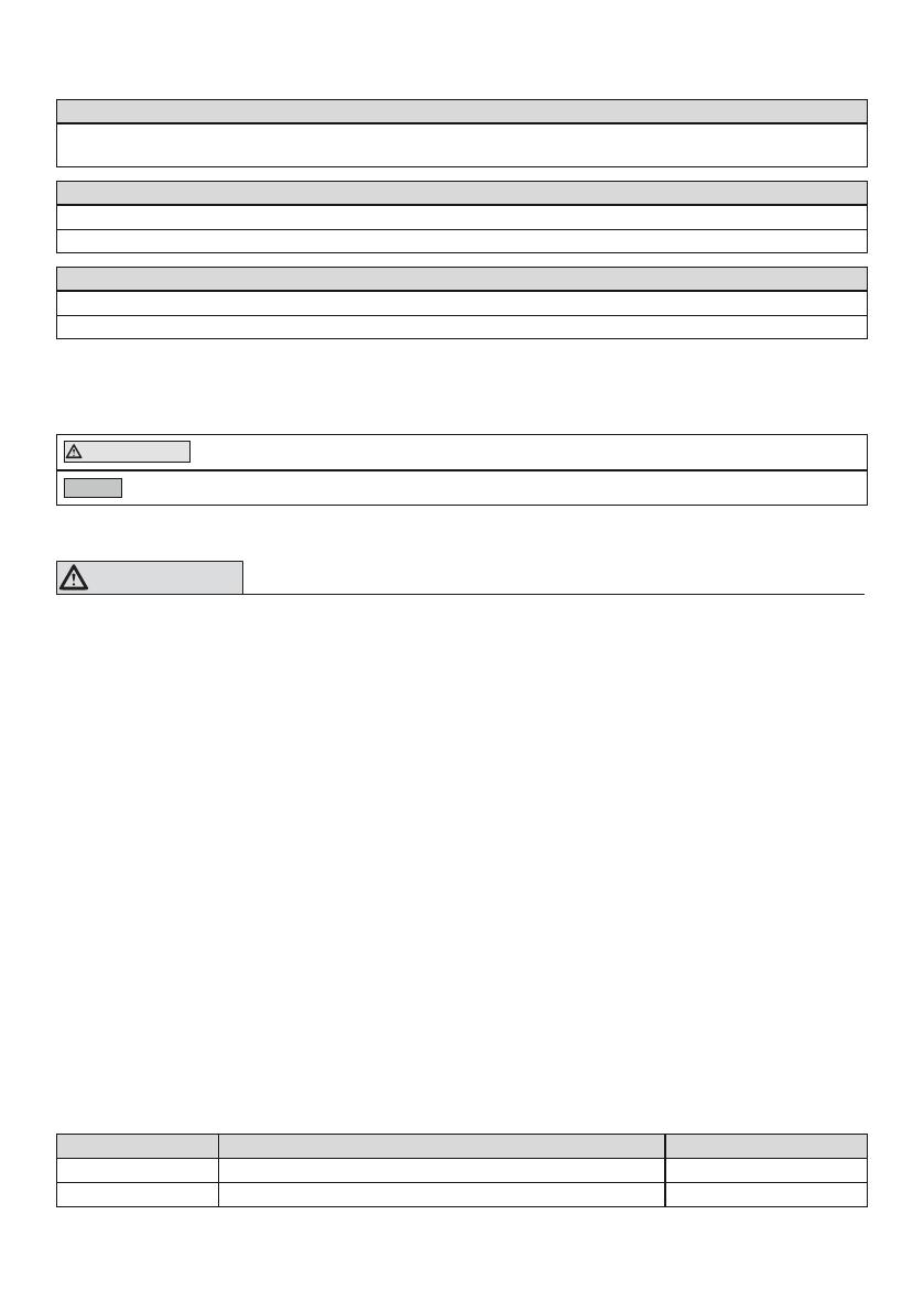
Almacenamiento y transporte
Margen de temperatura de –20°C a +60°C, humedad relativa del 20% al 90%, sin vibraciones mecánicas
ni impactos
Condiciones ambientales permitidas
Margen de temperatura: –10°C a +45°C
Humedad: humedad relativa: del 20% al 90%, sin condensación
Condiciones ambientales no permitidas
Sustancias químicas/líquidos: agua dulce, agua salada, sudor, orina, ácidos, lejía jabonosa, agua clorada
Sustancias sólidas: polvo, arena, partículas altamente higroscópicas (p.ej., polvos de talco)
3 Seguridad
3.1 Significado de los símbolos de advertencia
PRECAUCIÓN Advertencias sobre posibles riesgos de accidentes y lesiones.
AVISO Advertencias sobre posibles daños técnicos.
3.2 Indicaciones generales de seguridad
¡PRECAUCIÓN!
Riesgo de lesiones y de dañar el producto
Respete el ámbito de uso del producto y no lo someta a sobrecargas (véase la página17).
Observe las combinaciones posibles/no permitidas indicadas en las instrucciones de uso de
los productos.
No exponga el producto a condiciones ambientales no permitidas.
Compruebe que el producto no presente daños después haber estado expuesto a condicio
nes ambientales no permitidas.
No utilice el producto si está dañado o si su estado fuera dudoso. Tome las medidas perti
nentes (p.ej., limpieza, reparación, sustitución o envío del producto al fabricante o a un taller
especializado para su revisión).
Tenga sumo cuidado al trabajar con el producto a fin de evitar daños mecánicos.
Compruebe que el producto funcione correctamente y que esté preparado para el uso si sos
pechara que está dañado.
No utilice el producto si su funcionamiento está limitado. Tome las medidas pertinentes
(p.ej., limpieza, reparación, sustitución o envío del producto al fabricante o a un taller espe
cializado para su revisión).
Signos de alteraciones o fallos en el funcionamiento durante el uso
Las alteraciones en el funcionamiento pueden ponerse de manifiesto en forma de, p. ej., un mo
delo de marcha distinto, un posicionamiento distinto de los componentes protésicos entre sí, así
como la aparición de ruidos.
4 Componentes incluidos en el suministro
Cantidad Denominación Referencia
1 Instrucciones de uso
1 Adaptador
19
5 Uso
PRECAUCIÓN
Alineamiento o montaje incorrecto
Riesgo de lesiones debido a daños en los componentes protésicos
Tenga en cuenta las indicaciones de alineamiento y montaje.
PRECAUCIÓN
Montaje incorrecto de las uniones de tornillos
Riesgo de lesiones debidas a la ruptura o al aflojamiento de las uniones de tornillos
Limpie las roscas antes de cada montaje.
Aplique estrictamente los pares de apriete indicados.
Respete las indicaciones referentes a la longitud de los tornillos y a la fijación de los mis
mos.
5.1 Montar el adaptador
En el adaptador a rosca deslizable están premontados los adaptadores de encaje. Hay un aloja
miento del núcleo de ajuste en proximal y un núcleo de ajuste en distal. Es posible cambiar los
adaptadores de encaje. El adaptador a rosca deslizable se monta en la prótesis durante el alinea
miento básico (p.ej., entre la articulación de rodilla protésica y el encaje o entre el pie protésico y
el encaje).
Opcional: cambiar el adaptador de encaje
1) Desmonte el adaptador de encaje disponible.
2) Monte el adaptador de encaje según se indica en sus instrucciones de uso.
Conexión del núcleo de ajuste y del alojamiento del núcleo de ajuste
>Materiales necesarios: llave dinamométrica (p.ej., 710D20)
1) Enrosque las varillas roscadas y apriételas con la llave dinamométrica (10Nm).
2) Sustituya las varillas roscadas que sobresalgan demasiado o estén insertadas con demasiada
profundidad por varillas roscadas adecuadas (véase la tabla de selección).
Tabla de selección para varillas roscadas
Referencia Longitud (mm)
506G3=M8X12-V 12
506G3=M8X14 14
506G3=M8X16 16
Ajuste
Las varillas roscadas del alojamiento del núcleo de ajuste permiten realizar correcciones estáti
cas durante el alineamiento, durante las pruebas y también tras el acabado de la prótesis.
Recambio y desmontaje
La posición ajustada del componente protésico puede mantenerse en caso de recambio o des
montaje. Para ello, desenrosque las dos varillas roscadas que se han insertado más profunda
mente y que se encuentran una junto a la otra.
5.2 Ajustar el adaptador
El adaptador a rosca deslizable se utiliza durante la prueba estática y dinámica. La posición se
ajusta con los tornillos de ajuste y se asegura con tornillos de cabeza cilíndrica.
1) Afloje los tornillos de cabeza cilíndrica (véase fig.1).
2) ¡AVISO! Afloje los tornillos de cabeza cilíndrica antes de ajustar el adaptador con el
fin de evitar un mayor desgaste.
Ajuste la posición en el plano frontal y el plano sagital con los tornillos de ajuste (véase fig.2).
20
3) Apriete ligeramente los tornillos de cabeza cilíndrica para fijar la posición del adaptador
(véase fig.1).
5.3 Desmontar el adaptador
Una vez concluidos el alineamiento estático y la prueba dinámica, el adaptador se retira de la pró
tesis y se sustituye por los componentes protésicos definitivos. Para la transferencia de los pará
metros de alineamiento, Ottobock recomienda el aparato de transferencia 743A16.
6 Limpieza
1) Limpie el producto con un paño húmedo y suave.
2) Seque el producto con un paño suave.
3) Deje secar al aire la humedad residual.
7 Mantenimiento
Pasados los primeros 30días de utilización, los componentes protésicos deben ser someti
dos a una inspección visual y de funcionamiento.
Durante la revisión normal se ha de comprobar si la prótesis presenta desgastes.
Realizar inspecciones anuales de seguridad.
8 Eliminación
El producto no puede eliminarse en todas partes con residuos domésticos sin clasificar. Una eli
minación indebida puede tener consecuencias nocivas para el medioambiente y para la salud.
Observe las indicaciones de las autoridades competentes de su país relativas a la devolución, la
recogida y la eliminación.
9 Aviso legal
Todas las disposiciones legales se someten al derecho imperativo del país correspondiente al
usuario y pueden variar conforme al mismo.
9.1 Responsabilidad
El fabricante se hace responsable si este producto es utilizado conforme a lo descrito e indicado
en este documento. El fabricante no se responsabiliza de los daños causados debido al incumpli
miento de este documento y, en especial, por los daños derivados de un uso indebido o una mo
dificación no autorizada del producto.
10 Datos técnicos
Referencia 4R1
Peso (sin adaptador de encaje) [g] 465
Peso (con adaptador de encaje) [g] 610
Altura constructiva sin adaptador [mm] 46
Altura constructiva con adaptador [mm] 82
Altura de montaje [mm] 68
Altura del sistema [mm] 68
Desplazamiento máx. medial/lateral [mm] ±15
Desplazamiento máx. anterior/posterior [mm] ±25
Peso corporal máx. [kg] 100
  • Page 1 1
  • Page 2 2
  • Page 3 3
  • Page 4 4
  • Page 5 5
  • Page 6 6
  • Page 7 7
  • Page 8 8
  • Page 9 9
  • Page 10 10
  • Page 11 11
  • Page 12 12
  • Page 13 13
  • Page 14 14
  • Page 15 15
  • Page 16 16
  • Page 17 17
  • Page 18 18
  • Page 19 19
  • Page 20 20
  • Page 21 21
  • Page 22 22
  • Page 23 23
  • Page 24 24
  • Page 25 25
  • Page 26 26
  • Page 27 27
  • Page 28 28
  • Page 29 29
  • Page 30 30
  • Page 31 31
  • Page 32 32

Ottobock 4R1 Manuale utente

Tipo
Manuale utente