
Gebrauchsanweisung ............................. 5
Instructions for use ................................. 9
Instructions d'utilisation........................... 13
Istruzioni per l’uso .................................. 17
Instrucciones de uso............................... 22
Manual de utilização................................ 26
Gebruiksaanwijzing................................. 31
Bruksanvisning....................................... 35
Brugsanvisning ...................................... 39
Bruksanvisning....................................... 43
Käyttöohje.............................................. 47
Instrukcja użytkowania............................. 51
Használati utasítás .................................. 56
Návod k použití....................................... 60
Instrucţiuni de utilizare............................. 65
Upute za uporabu ................................... 69
Navodila za uporabo ............................... 73
Návod na používanie ............................... 77
Инструкция за употреба......................... 82
Kullanma talimatı .................................... 86
Οδηγίες χρήσης ..................................... 91
Руководство по применению .................. 95
取扱説明書............................................. 100
使用说明书............................................. 104
사용 설명서............................................ 108
2R40=*, 2R41=*, 2R48, 4R66

1
2

2
3

3
4

1 Produktbeschreibung Deutsch
INFORMATION
Datum der letzten Aktualisierung: 2021-06-07
►Lesen Sie dieses Dokument vor Gebrauch des Produkts auf
merksam durch und beachten Sie die Sicherheitshinweise.
►Weisen Sie den Benutzer in den sicheren Gebrauch des Pro
dukts ein.
►Wenden Sie sich an den Hersteller, wenn Sie Fragen zum Pro
dukt haben oder Probleme auftreten.
►Melden Sie jedes schwerwiegende Vorkommnis im Zusammen
hang mit dem Produkt, insbesondere eine Verschlechterung des
Gesundheitszustands, dem Hersteller und der zuständigen Be
hörde Ihres Landes.
►Bewahren Sie dieses Dokument auf.
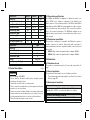
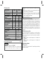
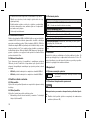
1.1 Konstruktion und Funktion
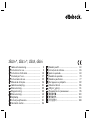
Die Kinder Fußadapter 2R40=1 und 2R40=2 dienen der Verbindung
eines Kinder-SACH-Fußes oder eines Kinder-Dynamik-Fußes mit dem
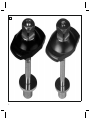
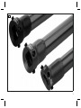
distalen Anschluss der Modularprothese. Die Rohradapter 2R41=1,
2R41=2 und der Schraubadapter 4R66 werden als Bauteile in Modu
lar-Beinprothesen eingesetzt. Sie verbinden den Prothesenfuß mit den
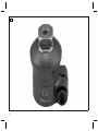
proximalen Bauteilen. Der Rohradapter 2R48 verfügt über einen ge
winkelten Anschluss und wird als Verbindung zwischen einem Prothe
senkniegelenk und einem Prothesenhüftgelenk eingesetzt.
1.2 Kombinationsmöglichkeiten
Diese Prothesenkomponente ist kompatibel mit dem Ottobock Modu
larsystem für Kinder. Die Funktionalität mit Komponenten anderer
Hersteller, die über kompatible modulare Verbindungselemente verfü
gen, wurde nicht getestet.
•2R41=1: Das Produkt nur mit dem Fußadapter 2R40=1 kombinie
ren.
•2R41=2: Das Produkt nur mit dem Fußadapter 2R40=2 kombinie
ren.
2 Bestimmungsgemäße Verwendung
2.1 Verwendungszweck
Das Produkt ist ausschließlich für die exoprothetische Versorgung der
unteren Extremität einzusetzen.
2.2 Einsatzgebiet
Das Produkt wurde für den Einsatz in einer Kinderprothese entwickelt.
• Das maximal zugelassene Körpergewicht ist in den Technischen
Daten angegeben (siehe Seite8).
2.3 Umgebungsbedingungen
Lagerung und Transport
Temperaturbereich –20°C bis +60°C, relative Luftfeuchtigkeit
20% bis 90%, keine mechanischen Vibrationen oder Stöße
Zulässige Umgebungsbedingungen
Temperaturbereich: –10°C bis +45°C
Feuchtigkeit: relative Luftfeuchtigkeit: 20% bis 90%, nicht kon
densierend
Unzulässige Umgebungsbedingungen
Chemikalien/Flüssigkeiten: Süßwasser, Salzwasser, Schweiß,
Urin, Säuren, Seifenlauge, Chlorwasser
Feststoffe: Staub, Sand, stark hygroskopische Partikel (z.B. Tal
kum)
2.4 Lebensdauer
Das Produkt wurde vom Hersteller mit 3 Millionen Belastungszyklen
geprüft. Dies würde bei einer Prothese für Erwachsene einer Lebens
dauer von max. 5 Jahren entsprechen. Die Lebensdauer des Produkts
kann nicht generell festgelegt werden, weil bei der Nutzung durch
Kinder stark unterschiedliche Belastungen auftreten.
5

3 Sicherheit
3.1 Bedeutung der Warnsymbolik
VORSICHT Warnung vor möglichen Unfall- und Verletzungsge
fahren.
3.2 Allgemeine Sicherheitshinweise
VORSICHT!
Verletzungsgefahr und Gefahr von Produktschäden
►Halten Sie das Einsatzgebiet des Produkts ein und setzen Sie es
keiner Überbeanspruchung aus (siehe Seite5).
►Beachten Sie die Kombinationsmöglichkeiten/Kombinationsaus
schlüsse in den Gebrauchsanweisungen der Produkte.
►Setzen Sie das Produkt keinen unzulässigen Umgebungsbedin
gungen aus.
►Prüfen Sie das Produkt auf Schäden, wenn es unzulässigen Um
gebungsbedingungen ausgesetzt war.
►Verwenden Sie das Produkt nicht, wenn es beschädigt oder in ei
nem zweifelhaften Zustand ist. Ergreifen Sie geeignete Maßnah
men: (z.B. Reinigung, Reparatur, Ersatz, Kontrolle durch den
Hersteller oder eine Fachwerkstatt).
►Arbeiten Sie sorgfältig mit dem Produkt um mechanische Beschä
digung zu verhindern.
►Prüfen Sie das Produkt auf Funktion und Gebrauchsfähigkeit,
wenn Sie Schäden vermuten.
►Verwenden Sie das Produkt nicht, wenn seine Funktion einge
schränkt ist. Ergreifen Sie geeignete Maßnahmen: (z.B. Reini
gung, Reparatur, Ersatz, Kontrolle durch den Hersteller oder eine
Fachwerkstatt)
Funktionsveränderungen können sich z.B. durch ein verändertes
Gangbild, eine veränderte Positionierung der Prothesenkomponenten
zueinander sowie durch Geräuschentwicklung bemerkbar machen.
6
4 Lieferumfang
Menge Benennung Kennzeichen
1 Gebrauchsanweisung –
1 Adapter –
Nur Rohradapter 2R41=*, 2R48
4 Gewindestift 506G3=M6x10
Nur Schraubadapter 4R66
1 Flachkopfschraube 501S42=M6x18
Ersatzteile/Zubehör (nicht im Lieferumfang)
Menge Benennung Kennzeichen
636W28Spezialklebstoff mit Härter
636W18 und 636W19
Einzelteile-Pack für 2R40=1 bestehend
aus: 1 Zylinderschraube, 1 Unterlegschei
be
2D6=M8
Einzelteile-Pack für 2R40=2 bestehend
aus: 1 Zylinderschraube, 1 Unterlegschei
be
2D6=M6
5 Gebrauchsfähigkeit herstellen
VORSICHT
Fehlerhafter Aufbau oder Montage
Verletzungsgefahr durch Schäden an Prothesenkomponenten
►Beachten Sie die Aufbau- und Montagehinweise.
VORSICHT
Fehlerhafte Montage der Schraubverbindungen
Verletzungsgefahr durch Bruch oder Lösen der Schraubverbindun
gen
►Reinigen Sie die Gewinde vor jeder Montage.
►Halten Sie die vorgegebenen Anzugsmomente ein.

►Beachten Sie die Anweisungen zur Länge der Schrauben und
zur Schraubensicherung.
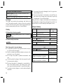
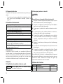
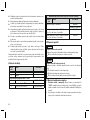
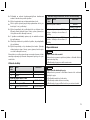
5.1 Fußadapter montieren
>Benötigte Werkzeuge und Materialien: Schleifwerkzeug,
Drehmomentschlüssel 710D20, entfettender Reiniger (z.B. Ace
ton 634A3), Spezialklebstoff und Härter (siehe Seite6, Tabelle
Ersatzteile/Zubehör)
1) Bei Prothesenfüßen mit Holzkomponenten die Anschlussfläche
aufrauen und die Schleifrückstände entfernen.
2) INFORMATION: Der Fußadapter muss mit dem Prothesenfuß
verklebt werden. Dazu den angegebenen Spezialklebstoff
verwenden.
Den Spezialkleber und den Härter gut miteinander vermischen
und auf die Anschlussfläche auftragen.
3) Bei Verschmutzungen (z.B. durch Fett) die Metallklebefläche des
Fußadapters mit einem entfettenden Reiniger reinigen.
4) Den Fußadapter auf dem Prothesenfuß positionieren, die Schrau
be mit der Unterlegscheibe von unten durchstecken und anziehen
(Anzugsmoment: 2 bis 4Nm).
5) Die Verschraubung nach 3 bis 4 Stunden mit dem erforderlichen
Anzugsmoment (siehe Tabelle) nachziehen.
6) Die Verklebung aushärten lassen (16Stunden bei 20°C - Bei
niedrigeren Temperaturen verlängert sich die Zeit.).
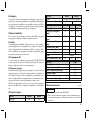
Anzugsmoment [Nm]Kennzei
chen
Prothe
senfuß-
Größe
[cm]
Prothesenfüße
mit Holzkompo
nenten
Prothesenfüße mit
Kunststoffkompo
nenten
2R40=2 12-17 10 –
2R40=1 18-21 20 –
7
5.2 Rohradapter anpassen
VORSICHT
Falsches Bearbeiten des Rohrs
Sturz durch Beschädigung am Rohr
►Spannen Sie das Rohr nicht in einen Schraubstock ein.
►Kürzen Sie das Rohr nur mit einem Rohrabschneider oder einer
Ablängvorrichtung.
VORSICHT
Falsche Montage des Rohrs
Verletzungsgefahr durch Bruch tragender Teile
►Schieben Sie das Rohr bei der Montage vollständig, bis zum An
schlag in die dafür vorgesehene Prothesenkomponente.
>Benötigte Materialien: Rohrabschneider 719R3 oder Ablängvor
richtung 704Y14*, Rohrentgrater 718R1
1) Das Rohr auf die erforderliche Länge kürzen.
2) Die Schnittkante mit dem Rohrentgrater innen und außen entgra
ten.
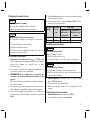
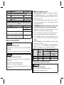
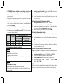
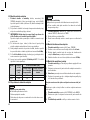
5.3 Schraubadapter montieren
>Benötigte Materialien: Drehmomentschlüssel (z.B. 710D20)
1) Die Zylinderschraube der Rohrklemmung 2Umdrehungen lösen.
2) Den Rohradapter vollständig, bis zum Anschlag, in den Schraub
adapter einstecken. Den Klemmschlitz anterior ausrichten.
3) Die Zylinderschraube anziehen (Anzugsmoment: 10Nm).
5.4 In Modularprothese montieren
>Benötigte Materialien: Siehe Gebrauchsanweisungen der An
schlusskomponenten
1) Die Justierkernaufnahme des Rohradapters in der Prothese distal
anordnen.
2) Den Klemmschlitz eines Schraubadapters anterior ausrichten.
3) Die Anschlusskomponenten gemäß den Anweisungen ihrer Ge
brauchsanweisungen mit dem Rohradapter verbinden.

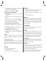
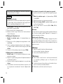
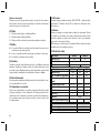
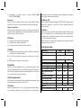
Justierkern und Justierkernaufnahme verbinden
Der Justierkern wird mit den Gewindestiften der Justierkernaufnahme
fixiert.
>Benötigte Materialien: Drehmomentschlüssel 710D20, Loctite
636K13
1) Justierkern und Justierkernaufnahme zusammenstecken.
2) Bei definitiver Montage: Die Gewindestifte mit Loctite benet
zen.
3) Die Gewindestifte einschrauben und anziehen (2R41=1:9Nm,
2R41=2, 2R48:7Nm).
Justierung
Die Gewindestifte der Justierkernaufnahme ermöglichen statische
Korrekturen während des Aufbaus, der Anprobe und nach Fertigstel
lung der Prothese.
Austausch und Demontage
Die eingestellte Position der Prothesenkomponente kann bei Aus
tausch oder Demontage beibehalten werden. Dazu die beiden am
tiefsten eingeschraubten, nebeneinanderliegenden Gewindestifte her
ausschrauben.
6 Reinigung
1) Das Produkt mit einem feuchten, weichen Tuch reinigen.
2) Das Produkt mit einem weichen Tuch abtrocknen.
3) Die Restfeuchtigkeit an der Luft trocknen lassen.
7 Wartung
►Die Prothesenkomponenten nach den ersten 30Tagen Gebrauch
einer Sichtprüfung und Funktionsprüfung unterziehen.
►Die komplette Prothese während der normalen Konsultation auf
Abnutzung überprüfen.
►Jährliche Sicherheitskontrollen durchführen.
8
8 Entsorgung
Das Produkt darf nicht überall mit unsortiertem Hausmüll entsorgt
werden. Eine unsachgemäße Entsorgung kann sich schädlich auf die
Umwelt und die Gesundheit auswirken. Beachten Sie die Angaben
der zuständigen Behörde Ihres Landes zu Rückgabe, Sammel- und
Entsorgungsverfahren.
9 Rechtliche Hinweise
Alle rechtlichen Bedingungen unterliegen dem jeweiligen Landesrecht
des Verwenderlandes und können dementsprechend variieren.
9.1 Haftung
Der Hersteller haftet, wenn das Produkt gemäß den Beschreibungen
und Anweisungen in diesem Dokument verwendet wird. Für Schäden,
die durch Nichtbeachtung dieses Dokuments, insbesondere durch
unsachgemäße Verwendung oder unerlaubte Veränderung des Pro
dukts verursacht werden, haftet der Hersteller nicht.
9.2 CE-Konformität
Das Produkt erfüllt die Anforderungen der Verordnung (EU) 2017/745
über Medizinprodukte. Die CE-Konformitätserklärung kann auf der
Website des Herstellers heruntergeladen werden.
9.3 Garantie
Der Hersteller gewährt auf das Produkt eine Garantie ab Kaufdatum.
Von der Garantie sind Mängel umfasst, die nachweislich auf Material-,
Fertigungs- oder Konstruktionsfehlern beruhen und innerhalb des Ga
rantiezeitraums dem Hersteller gegenüber geltend gemacht werden.
Nähere Informationen zu den Garantiebedingungen erteilt die zustän
dige Vertriebsgesellschaft des Herstellers.
10 Technische Daten
Kennzeichen 2R40=1 2R40=2
Gewicht [g] 80 45
Material Aluminium/Edelstahl, rostfrei
Max. Körpergewicht [kg] 45 35

Kennzeichen 2R41=1 2R41=2 2R48
Gewicht [g] 140 125 105
Min. Systemhöhe [mm] 79 78 81
Max. Systemhöhe [mm] 323 282 225
Einbauhöhe [mm] min. 45 min. 45 min. 45
Gesamtlänge [mm] 314 274 220
Durchmesser [mm] 22 22 22
Abwinkelung [°] – – 13
Material Aluminium
Max. Körpergewicht [kg] 45 35 45
Kennzeichen 4R66
Gewicht [g] 45
Systemhöhe [mm] -9
Einbauhöhe [mm] 29
Durchmesser [mm] 22
Material Aluminium
Max. Körpergewicht [kg] 45
1 Product description English
INFORMATION
Date of last update: 2021-06-07
►Please read this document carefully before using the product
and observe the safety notices.
►Instruct the user in the safe use of the product.
►Please contact the manufacturer if you have questions about the
product or in case of problems.
►Report each serious incident related to the product to the manu
facturer and to the relevant authority in your country. This is par
ticularly important when there is a decline in the health state.
►Please keep this document for your records.
9
1.1 Construction and Function
The 2R40=1 and 2R40=2 foot adapters for children are used to con
nect a SACH foot for children or a dynamic foot for children to the
distal connector of the modular prosthesis. The 2R41=1 and 2R41=2
tube adapters and the 4R66 tube clamp adapter are used as compon
ents for modular lower limb prostheses. They connect the prosthetic
foot to the proximal components. The 2R48 tube adapter has an
angled connector and is used to join a prosthetic knee joint to a pros
thetic hip joint.
1.2 Combination possibilities
This prosthetic component is compatible with Ottobock's system of
modular connectors for children. Functionality with components of
other manufacturers that have compatible modular connectors has not
been tested.
•2R41=1: Only combine the product with foot adapter 2R40=1.
•2R41=2: Only combine the product with foot adapter 2R40=2.
2 Intended use
2.1 Indications for use
The product is intended exclusively for lower limb exoprosthetic fit
tings.
2.2 Area of application
The product was developed for use in a children's prosthesis.
• The maximum approved body weight is specified in the technical
data (see page13).
2.3 Environmental conditions
Storage and transport
Temperature range –20°C to +60°C (–4°F to +140°F), relative
humidity 20% to 90%, no mechanical vibrations or impacts
Allowable environmental conditions
Temperature range: –10°C to +45°C (14°F to 113°F)
Moisture: relative humidity: 20%to90%, non-condensing

Unacceptable environmental conditions
Chemicals/liquids: fresh water, salt water, perspiration, urine,
acids, soapsuds, chlorine water
Solids: dust, sand, highly hygroscopic particles (e.g. talcum)
2.4 Lifetime
This product was tested by the manufacturer with 3million load
cycles. This would correspond to a lifetime of 5years for a prosthesis
for adults. The lifetime of the product cannot be generally determined
because loads vary widely in the course of use by children.
3 Safety
3.1 Explanation of warning symbols
CAUTION Warning regarding possible risks of accident or
injury.
3.2 General safety instructions
CAUTION!
Risk of injury and risk of product damage
►Comply with the product's field of application and do not expose
it to excessive strain (see page9).
►Note the combination possibilities/combination exclusions in the
instructions for use of the products.
►Do not expose the product to prohibited environmental condi
tions.
►Check the product for damage if it has been exposed to prohib
ited environmental conditions.
►Do not use the product if it is damaged or in a questionable con
dition. Take suitable measures (e.g.cleaning, repair, replace
ment, inspection by the manufacturer or a specialist workshop).
►To prevent mechanical damage, use caution when working with
the product.
10
►If you suspect the product is damaged, check it for proper func
tion and readiness for use.
►Do not use the product if its functionality is restricted. Take suit
able measures (e.g.cleaning, repair, replacement, inspection by
the manufacturer or a specialist workshop).
Among other factors, changes in functionality can be indicated by an
altered gait pattern, a change in the positioning of the prosthetic com
ponents relative to each other and by the development of noises.
4 Scope of delivery
Quantity Designation Reference num
ber
1 Instructions for use –
1 Adapter –
2R41=*, 2R48 tube adapter only
4 Set screw 506G3=M6x10
4R66 tube clamp adapter only
1 Flat head screw 501S42=M6x18
Spare parts/accessories (not included in the scope of deliv
ery)
Quantity Designation Reference number
636W28Special adhesive with hardener
636W18 and 636W19
Single-component pack for 2R40=1 con
sisting of: one cap screw, one washer
2D6=M8
Single-component pack for 2R40=2 con
sisting of: one cap screw, one washer
2D6=M6

5 Preparing the product for use
CAUTION
Incorrect alignment or assembly
Risk of injury due to damaged prosthetic components
►Observe the alignment and assembly instructions.
CAUTION
Improper assembly of the screw connections
Risk of injury due to breakage or loosening of the screw connec
tions
►Clean the threads before every installation.
►Apply the specified torque values.
►Follow the instructions regarding the length of the screws and
about how to secure the screws.
5.1 Installing the foot adapter
>Required tools and materials: Grinding tool, 710D20 torque
wrench, degreasing cleaning agent (e.g. 634A3 acetone), special
adhesive and hardener (see page10, table of spare
parts/accessories)
1) For prosthetic feet with wooden components, roughen the con
nection surface and remove the grinding dust.
2) INFORMATION: The foot adapter has to be glued to the
prosthetic foot. Use the specified special adhesive for this
purpose.
Mix the special adhesive and hardener well together and apply to
the connection surface.
3) Clean any soiling (e.g.caused by grease) on the metal surface of
the foot adapter to be glued with a degreasing cleaning agent.
4) Position the foot adapter on the prosthetic foot, insert the screw
and washer from below and tighten it (installation torque: 2 to
4Nm).
11
5) After 3 to 4 hours, tighten the screw connection with the required
installation torque (see table).
6) Leave the glued surface to harden (16hours at 20°C – the time
increases for lower temperatures).
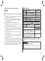
Torque [Nm]Reference
number
Prosthetic
foot size
[cm] Prosthetic feet
with wooden
components
Prosthetic feet
with plastic com
ponents
2R40=2 12-17 10 –
2R40=1 18-21 20 –
5.2 Adjusting the tube adapter
CAUTION
Incorrect processing of tube
Fall due to damage to the tube
►Do not clamp the tube into a vice.
►To shorten the tube, use only a tube cutter or a cutting device.
CAUTION
Incorrect mounting of the tube
Risk of injury due to breakage of load-bearing components
►Slide the tube all the way to the stop in the intended prosthetic
component when mounting.
>Required materials: 719R3 tube cutter or 704Y14* cutting
device, 718R1 tube deburrer
1) Shorten the tube to the required length.
2) Deburr the inside and outside of the cut edge with the tube
deburrer.
5.3 Installing the tube clamp adapter
>Required materials: torque wrench (e.g.710D20)
1) Loosen the tube clamp cap screw by twoturns.

2) Insert the tube adapter fully into the tube clamp adapter up to the
stop. Align the clamping slot anteriorly.
3) Tighten the cap screw (tightening torque: 10Nm).
5.4 Installation in the modular prosthesis
>Required materials: See instructions for use of the connection
components
1) Position the pyramid receiver of the tube adapter distally in the
prosthesis.
2) Align the clamping slot of one tube clamp adapter anteriorly.
3) Connect the connection components to the tube adapter as
described in the respective instructions for use.
Connecting the pyramid adapter and pyramid receiver
The pyramid adapter is fixed with the set screws of the pyramid receiv
er.
>Required materials: 710D20 torque wrench, 636K13 Loctite
1) Connect the pyramid to the pyramid receiver.
2) For final assembly: Coat the set screws with Loctite.
3) Screw the set screws in and tighten (2R41=1:9Nm, 2R41=2,
2R48:7Nm).
Alignment
The set screws in the pyramid receiver can be used to make static
adjustments during alignment, trial fittings and after the prosthesis is
finished.
Replacement and disassembly
The set position of the prosthetic component can be maintained dur
ing replacement or disassembly. In order to do this, unscrew the two
set screws that are screwed in the furthest and located next to each
other.
6 Cleaning
1) Clean the product with a damp, soft cloth.
2) Dry the product with a soft cloth.
3) Allow to air dry in order to remove residual moisture.
12
7 Maintenance
►A visual inspection and functional test of the prosthetic compon
ents should be performed after the first 30days of use.
►Inspect the entire prosthesis for wear during normal consulta
tions.
►Conduct annual safety inspections.
8 Disposal
In some jurisdictions it is not permissible to dispose of the product
with unsorted household waste. Improper disposal can be harmful to
health and the environment. Observe the information provided by the
responsible authorities in your country regarding return, collection
and disposal procedures.
9 Legal information
All legal conditions are subject to the respective national laws of the
country of use and may vary accordingly.
9.1 Liability
The manufacturer will only assume liability if the product is used in
accordance with the descriptions and instructions provided in this
document. The manufacturer will not assume liability for damage
caused by disregarding the information in this document, particularly
due to improper use or unauthorised modification of the product.
9.2 CE conformity
The product meets the requirements of Regulation (EU) 2017/745 on
medical devices. The CE declaration of conformity can be down
loaded from the manufacturer's website.
9.3 Warranty
The manufacturer warrants this device from the date of purchase. The
warranty covers defects that can be proven to be a direct result of
flaws in the material, production or construction and that are reported
to the manufacturer within the warranty period.
Further information on the warranty terms and conditions can be
obtained from the competent manufacturer distribution company.

10 Technical data
Reference number 2R40=1 2R40=2
Weight [g] 80 45
Material Aluminium/stainless steel
Max. body weight [kg] 45 35
Reference number 2R41=1 2R41=2 2R48
Weight [g] 140 125 105
Min. system height [mm] 79 78 81
Max. system height [mm] 323 282 225
Build height [mm] Min. 45 Min. 45 Min. 45
Overall length [mm] 314 274 220
Diameter [mm] 22 22 22
Angling [°] – – 13
Material Aluminium
Max. body weight [kg] 45 35 45
Reference number 4R66
Weight [g] 45
System height [mm] -9
Build height [mm] 29
Diameter [mm] 22
Material Aluminium
Max. body weight [kg] 45
1 Description du produit Français
INFORMATION
Date de la dernière mise à jour: 2021-06-07
►Veuillez lire attentivement l’intégralité de ce document avant
d’utiliser le produit ainsi que respecter les consignes de sécuri
té.
13
►Apprenez à l’utilisateur comment utiliser son produit en toute sé
curité.
►Adressez-vous au fabricant si vous avez des questions concer
nant le produit ou en cas de problèmes.
►Signalez tout incident grave survenu en rapport avec le produit,
notamment une aggravation de l’état de santé, au fabricant et à
l’autorité compétente de votre pays.
►Conservez ce document.
1.1 Conception et fonctionnement
Les adaptateurs de pied pour enfants 2R40=1 et 2R40=2 établissent
la liaison entre un pied SACH pour enfants ou un pied dynamique
pour enfants et le raccord distal de la prothèse modulaire. Les adap
tateurs tubulaires 2R41=1, 2R41=2 et l'adaptateur à vis 4R66 sont uti
lisés comme composants des prothèses de jambe modulaires. Ils re
lient le pied prothétique aux composants proximaux. L’adaptateur tu
bulaire 2R48 dispose d’un raccord angulaire et est utilisé pour relier
une articulation de genou prothétique à une articulation de hanche
prothétique.
1.2 Combinaisons possibles
Ce composant prothétique est compatible avec le système modulaire
Ottobock pour enfants. Le fonctionnement avec des composants
d’autres fabricants disposant de connecteurs modulaires compatibles
n’a pas été testé.
•2R41=1: combinez le produit uniquement avec l’adaptateur de
pied 2R40=1.
•2R41=2: combinez le produit uniquement avec l’adaptateur de
pied 2R40=2.
2 Utilisation conforme
2.1 Usage prévu
Le produit est exclusivement destiné à l’appareillage exoprothétique
des membres inférieurs.

2.2 Domaine d’application
Ce produit a été conçu pour une utilisation dans une prothèse pour
enfants.
• Le poids corporel maximum admissible est indiqué dans le cha
pitre consacré aux caractéristiques techniques (consulter la
page17).
2.3 Conditions d’environnement
Entreposage et transport
Plage de températures –20°C à +60°C, humidité relative 20% à
90%, aucune vibration mécanique ou choc
Conditions d’environnement autorisées
Plage de températures: –10°C à +45°C
Humidité: humidité relative de l’air: 20% à 90%, sans conden
sation
Conditions d’environnement non autorisées
Produits chimiques/liquides: eau douce, eau salée, transpira
tion, urine, acides, eau savonneuse, eau chlorée
Particules solides: poussières, grains de sable, particules forte
ment hygroscopiques (talc parex.)
2.4 Durée de vie
Le fabricant a contrôlé le produit en le soumettant à 3millions de
cycles de charge. Ceci correspond à une durée de vie de 5 ans maxi
mum pour une prothèse pour adultes. En général, la durée de vie
exacte ne peut pas être définie pour le produit, car il est soumis à des
sollicitations très différentes lorsqu’il est utilisé par des enfants.
3 Sécurité
3.1 Signification des symboles de mise en garde
PRUDENCE Mise en garde contre les éventuels risques
d’accidents et de blessures.
14
3.2 Consignes générales de sécurité
PRUDENCE!
Risque de blessure et risque de détérioration du produit
►Respecter le domaine d’application du produit et ne pas l’exposer
à une sollicitation excessive (consulter la page14).
►Respecter les combinaisons possibles/exclues qui sont indiquées
dans les notices d’utilisation des produits.
►Ne pas exposer le produit à des conditions ambiantes non autori
sées.
►En cas d’exposition à des conditions ambiantes non autorisées,
vérifier que le produit n’a subi aucun dommage.
►Ne pas utiliser le produit s’il est endommagé ou en cas de doute
sur son état. Prendre les mesures nécessaires (p.ex. nettoyage,
réparation, remplacement, contrôle par le fabricant ou un atelier
spécialisé).
►Manipuler le produit avec précaution pour éviter toute dommage
mécanique.
►En cas de doute sur l’état du produit, vérifier qu’il est bien en état
de fonctionner.
►Ne pas utiliser le produit si sa fonctionnalité est limitée. Prendre
les mesures nécessaires (p.ex. nettoyage, réparation, remplace
ment, contrôle par le fabricant ou un atelier spécialisé).
Une modification de la démarche, un changement du positionnement
des composants prothétiques les uns par rapport aux autres ainsi que
l’émission de bruits constituent des exemples de signes qui
confirment des modifications de la fonctionnalité.
4 Contenu de la livraison
Quantité Désignation Référence
1 Notice d’utilisation –
1 Adaptateur –

Quantité Désignation Référence
Uniquement pour adaptateur tubulaire 2R41=*, 2R48
4 Goujon fileté 506G3=M6x10
Uniquement pour adaptateur de vissage 4R66
1 Vis à tête plate 501S42=M6x18
Pièces de rechange/accessoires (non compris dans la livrai
son)
Quantité Désignation Référence
636W28Colle spéciale avec durcisseur
636W18 et 636W19
Kit de pièces détachées pour 2R40=1 com
prenant: 1vis à tête cylindrique, 1rondelle
2D6=M8
Kit de pièces détachées pour 2R40=2 com
prenant: 1vis à tête cylindrique, 1rondelle
2D6=M6
5 Mise en service du produit
PRUDENCE
Alignement ou montage incorrect
Risque de blessure occasionnée par des composants prothétiques
endommagés
►Respectez les consignes relatives à l’alignement et au montage.
PRUDENCE
Montage incorrect des raccords vissés
Risque de blessure provoqué par une rupture ou un desserrage des
raccords vissés
►Nettoyez les filets avant chaque montage.
►Respectez les couples de serrage prescrits.
►Respectez les consignes relatives à la longueur des vis et au blo
cage des vis.
15
5.1 Montage de l’adaptateur de pied
>Outils et matériel nécessaires: outil abrasif, clé dynamomé
trique 710D20, dégraissant (p.ex. acétone 634A3), colle spéciale
et durcisseur (consulter la page14, tableau des pièces de re
change/ accessoires)
1) En cas de pieds prothétiques dotés d’éléments en bois, grattez la
surface de raccordement afin de la rendre rugueuse et enlevez
les résidus de ponçage.
2) INFORMATION: L’adaptateur de pied doit être collé au pied
prothétique. Utilisez pour cela la colle spéciale indiquée.
Mélangez bien ensemble la colle spéciale et le durcisseur et ap
pliquez une couche sur la surface de raccordement.
3) En cas de salissures (p.ex. graisse), nettoyez la surface de col
lage métallique de l’adaptateur de pied avec un dégraissant.
4) Placez l’adaptateur de pied sur le pied prothétique, insérez la vis
avec la rondelle par le bas et serrez (couple de serrage: 2 à
4Nm).
5) Après 3 à 4heures, resserrez en appliquant le couple de serrage
nécessaire (voir tableau).
6) Laissez sécher le collage (16heures à une température de
20°C; plus longtemps en cas de températures inférieures).
Couple de serrage [Nm]Référence Taille du
pied pro
thétique
[cm]
Pieds prothé
tiques avec élé
ments en bois
Pieds prothétiques
avec éléments en
plastique
2R40=2 12-17 10 –
2R40=1 18-21 20 –
5.2 Ajustement de l’adaptateur tubulaire
PRUDENCE
Traitement inapproprié du tube
Chute provoquée par un endommagement du tube
►Ne serrez pas le tube dans un étau.

►Raccourcissez le tube uniquement à l’aide d’un coupe-tube ou
d’un dispositif de mise à longueur.
PRUDENCE
Montage incorrect du tube
Risque de blessure occasionnée par la rupture de pièces porteuses
►Lors du montage, insérez complètement le tube jusqu’à la butée
dans le composant prothétique prévu à cet effet.
>Matériel requis : coupe-tube 719R3 ou dispositif de mise à lon
gueur 704Y14*, ébavureur718R1
1) Raccourcissez le tube à la longueur requise.
2) Ébavurez l’arête de coupe à l’intérieur et à l’extérieur du tube à
l’aide de l’ébavureur.
5.3 Montage de l’adaptateur à vis
>Matériel et matériaux requis : clé dynamométrique (p.ex.
710D20)
1) Desserrez la vis à tête cylindrique du serrage tubulaire en effec
tuant 2tours.
2) Insérez complètement l’adaptateur tubulaire dans l’adaptateur à
vis, jusqu'à la butée. Orientez la fente de serrage en position an
térieure.
3) Serrez la vis à tête cylindrique (couple de serrage : 10Nm).
5.4 Montage dans la prothèse modulaire
>Matériel requis : voir les instructions d'utilisation des compo
sants de raccordement
1) Disposez le logement pour pyramide de l’adaptateur tubulaire du
côté distal de la prothèse.
2) Orientez la fente de serrage d'un adaptateur à vis en position an
térieure.
3) Conformément à leurs instructions d'utilisation respectives, reliez
les composants de raccordement à l'aide de l'adaptateur tubu
laire.
16
Raccordement de la pyramide et du logement pour pyramide
La pyramide est fixée avec les tiges filetées du logement pour pyra
mide.
>Matériel et matériaux requis : clé dynamométrique 710D20,
Loctite 636K13
1) Emboîtez la pyramide sur le logement pour pyramide.
2) Une fois le montage définitif : appliquez quelques gouttes de
Loctite sur les tiges filetées.
3) Vissez les tiges filetées et serrez-les (2R41=1:9Nm, 2R41=2,
2R48:7Nm).
Ajustement
Les tiges filetées du logement pour pyramide permettent d’effectuer
des corrections statiques pendant l’alignement et l’essayage de la
prothèse ainsi qu’après sa finition.
Remplacement et démontage
En cas de remplacement ou de démontage, le réglage de la position
du composant prothétique peut être maintenu. Pour cela, dévissez les
deux tiges filetées qui sont vissées le plus profondément et qui sont
placées côte à côte.
6 Nettoyage
1) Nettoyez le produit à l’aide d’un chiffon doux humide.
2) Séchez le produit à l’aide d’un chiffon doux.
3) Laissez sécher l’humidité résiduelle à l’air.
7 Maintenance
►Faites examiner (contrôle visuel et contrôle du fonctionnement)
les composants prothétiques après les 30 premiers jours
d’utilisation.
►Contrôlez la présence de traces d’usure sur l’ensemble de la pro
thèse au cours d’une consultation habituelle.
►Effectuez des contrôles de sécurité une fois par an.

8 Mise au rebut
Il est interdit d’éliminer ce produit n’importe où avec des ordures mé
nagères non triées. Une mise au rebut non conforme peut avoir des
répercussions négatives sur l’environnement et la santé. Respectez
les prescriptions des autorités compétentes de votre pays concernant
les procédures de retour, de collecte et de recyclage des déchets.
9 Informations légales
Toutes les conditions légales sont soumises à la législation nationale
du pays d’utilisation concerné et peuvent donc présenter des varia
tions en conséquence.
9.1 Responsabilité
Le fabricant est responsable si le produit est utilisé conformément aux
descriptions et instructions de ce document. Le fabricant décline
toute responsabilité pour les dommages découlant d’un non-respect
de ce document, notamment d’une utilisation non conforme ou d’une
modification non autorisée du produit.
9.2 Conformité CE
Ce produit répond aux exigences du Règlement (UE) 2017/745 relatif
aux dispositifs médicaux. La déclaration de conformité CE peut être
téléchargée sur le site Internet du fabricant.
9.3 Garantie commerciale
Le fabricant accorde pour ce produit une garantie commerciale à par
tir de la date d’achat. La garantie commerciale couvre les vices avérés
découlant d’un défaut de matériau, de fabrication ou de construction.
Ces vices doivent être signalés au fabricant pendant la période de va
lidité de la garantie commerciale.
La société de distribution du fabricant compétente dans votre pays
vous donnera de plus amples informations sur les conditions de la ga
rantie commerciale.
17
10 Caractéristiques techniques
Référence 2R40=1 2R40=2
Poids [g] 80 45
Matériau Aluminium / acier inoxydable
Poids max. du patient [kg] 45 35
Référence 2R41=1 2R41=2 2R48
Poids [g] 140 125 105
Hauteur min. du système
[mm]
79 78 81
Hauteur max. du système
[mm]
323 282 225
Hauteur de montage [mm] min. 45 min. 45 min. 45
Longueur totale [mm] 314 274 220
Diamètre [mm] 22 22 22
Angle [°] – – 13
Matériau Aluminium
Poids max. du patient [kg] 45 35 45
Référence 4R66
Poids [g] 45
Hauteur du système [mm] -9
Hauteur de montage [mm] 29
Diamètre [mm] 22
Matériau Aluminium
Poids max. du patient [kg] 45
1 Descrizione del prodotto Italiano
INFORMAZIONE
Data dell'ultimo aggiornamento: 2021-06-07

►Leggere attentamente il presente documento prima di utilizzare il
prodotto e osservare le indicazioni per la sicurezza.
►Istruire l'utente sull'utilizzo sicuro del prodotto.
►Rivolgersi al fabbricante in caso di domande sul prodotto o all'in
sorgere di problemi.
►Segnalare al fabbricante e alle autorità competenti del proprio
paese qualsiasi incidente grave in connessione con il prodotto,
in particolare ogni tipo di deterioramento delle condizioni di salu
te.
►Conservare il presente documento.
1.1 Costruzione e funzionamento
Gli adattatori per piede da bambino 2R40=1 e 2R40=2 servono a col
legare un piede protesico SACH o un piede dinamico da bambino
con l'attacco distale della protesi modulare. I tubi modulari 2R41=1,
2R41=2 e l'adattatore filettato 4R66 sono utilizzati come componenti
per protesi modulari di arto inferiore. Sono destinati a collegare il pie
de protesico ai componenti prossimali. Il tubo modulare 2R48 presen
ta un attacco angolato ed è utilizzato come collegamento tra un'artico
lazione di ginocchio protesica e un'articolazione d'anca protesica.
1.2 Possibilità di combinazione
Questo componente protesico è compatibile con il sistema modulare
Ottobock per bambini. Non è stata testata la funzionalità con compo
nenti di altri produttori che dispongono di elementi di collegamento
modulari compatibili.
•2R41=1: abbinare il prodotto solo all'adattatore del piede
2R40=1.
•2R41=2: abbinare il prodotto solo all'adattatore del piede
2R40=2.
2 Uso conforme
2.1 Uso previsto
Il prodotto deve essere utilizzato esclusivamente per protesi esosche
letriche di arto inferiore.
18
2.2 Campo d'impiego
Il prodotto è stato sviluppato per l'utilizzo in una protesi per bambini.
• Il peso corporeo massimo omologato è indicato nei dati tecnici (v.
pagina21).
2.3 Condizioni ambientali
Trasporto e immagazzinamento
Intervallo temperatura –20°C ... +60°C, umidità relativa dell'aria
20% ... 90%, in assenza di vibrazioni meccaniche o urti
Condizioni ambientali consentite
Intervallo temperatura: –10°C ... +45°C
Umidità: umidità relativa: 20% ... 90%, senza condensa
Condizioni ambientali non consentite
Sostanze chimiche/liquidi: acqua dolce, acqua salmastra, sudo
re, urina, acidi, acqua saponata, acqua clorata
Sostanze solide: polvere, sabbia, particelle molto igroscopiche
(p.es. talco)
2.4 Vita utile
Il prodotto è stato sottoposto dal fabbricante a 3 milioni di cicli di cari
co. Nel caso di una protesi per adulti ciò corrisponderebbe ad una vi
ta utile di max. 5 anni. Non è possibile prevedere la vita utile precisa
del prodotto, perché nel caso di utilizzo su bambini, le sollecitazioni
variano molto.
3 Sicurezza
3.1 Significato dei simboli utilizzati
CAUTELA Avvertenza relativa a possibili pericoli di incidente e
lesioni.

3.2 Indicazioni generali per la sicurezza
CAUTELA!
Pericolo di lesioni e di danni al prodotto
►Rispettare il campo d'impiego del prodotto e non sottoporlo a sol
lecitazioni eccessive (v. pagina18).
►Rispettare le possibilità/le esclusioni di abbinamento contenute
nelle istruzioni per l'uso dei prodotti.
►Non esporre il prodotto a condizioni ambientali non consentite.
►Se il prodotto è stato sottoposto a condizioni ambientali non con
sentite, controllare che non sia danneggiato.
►Non utilizzare il prodotto se è danneggiato o in uno stato che può
dare adito a dubbi. Prendere provvedimenti adeguati (p.es. puli
zia, riparazione, sostituzione, controllo da parte del fabbricante o
di un'officina specializzata)
►Utilizzare il prodotto in modo accurato per evitare eventuali danni
meccanici.
►Se si suppone che il prodotto sia danneggiato, controllarne il fun
zionamento e la possibilità di utilizzo.
►Non utilizzare il prodotto, se funziona solo limitatamente. Prende
re provvedimenti adeguati (p.es. pulizia, riparazione, sostituzio
ne, controllo da parte del fabbricante o di un'officina specializza
ta)
I cambiamenti funzionali sono riconoscibili ad esempio attraverso
un'alterazione dell'andatura, un diverso posizionamento dei compo
nenti della protesi e la produzione di rumori.
4 Fornitura
Quantità Denominazione Codice
1 Istruzioni per l’uso –
1 Adattatore –
Solo tubo modulare 2R41=*, 2R48
19
Quantità Denominazione Codice
4 Perno filettato 506G3=M6x10
Solo adattatore filettato 4R66
1 Vite a testa piatta 501S42=M6x18
Ricambi/accessori (non in dotazione)
Quantità Denominazione Codice
636W28Colla speciale con indurente
636W18 e 636W19
Set componenti singoli per 2R40=1 com
posto da: 1 vite a testa cilindrica, 1 rondel
la
2D6=M8
Set componenti singoli per 2R40=2 com
posto da: 1 vite a testa cilindrica, 1 rondel
la
2D6=M6
5 Preparazione all'uso
CAUTELA
Allineamento o montaggio errato
Pericolo di lesione per danni ai componenti della protesi
►Osservare le indicazioni per l'allineamento e il montaggio.
CAUTELA
Montaggio errato dei collegamenti a vite
Pericolo di lesione per caduta dovuta a rottura o allentamento dei
collegamenti a vite
►Pulire la filettatura prima di ogni montaggio.
►Rispettare le coppie di serraggio prescritte.
►Rispettare le istruzioni sulla lunghezza delle viti e sul relativo
bloccaggio.

5.1 Montaggio dell'attacco piede
>Utensili e materiali necessari: fresatrice, chiave dinamometrica
710D20, detergente sgrassante (ad es. acetone 634A3), colla
speciale e indurente (v. pagina19, tabella Ricambi/accessori)
1) Nel caso di piedi protesici con componenti in legno irruvidire la
superficie d'attacco e rimuovere i residui di fresatura.
2) INFORMAZIONE: L'attacco del piede deve essere incollato
con il piede protesico. Utilizzare la colla speciale indicata.
Mescolare bene la colla speciale e l'indurente e stenderli sulla su
perficie d'attacco.
3) In caso di imbrattamento (ades. dovuto a grasso), pulire con un
detergente sgrassante la superficie metallica di aderenza dell'at
tacco del piede.
4) Posizionare l'attacco sul piede protesico, infilare dal basso e
stringere la vite insieme alla rondella (coppia di serraggio: 2 - 4
Nm).
5) Dopo 3 - 4 ore serrare nuovamente il collegamento a vite con la
coppia di serraggio necessaria (cfr. tabella).
6) Far indurire il collante (per 16 ore a 20°C - in caso di temperature
inferiori il tempo sarà maggiore).
Coppia di serraggio [Nm]Codice Misura del
piede pro
tesico
[cm]
Piedi protesici
con componenti
in legno
Piedi protesici con
componenti in pla
stica
2R40=2 12-17 10 –
2R40=1 18-21 20 –
5.2 Adattamento del tubo modulare
CAUTELA
Preparazione errata del tubo
Caduta dovuta a danneggiamento del tubo
►Non serrare il tubo in una morsa!
►Tagliare il tubo solo con un tagliatubi o un dispositivo tranciante.
20
CAUTELA
Montaggio errato del tubo
Pericolo di lesione per rottura di componenti portanti
►Durante il montaggio inserire il tubo completamente, fino alla
battuta, nel relativo componente della protesi.
>Materiale necessario: tagliatubi 719R3 o dispositivo tranciante
704Y14*, sbavatore per tubi 718R1
1) Tagliare il tubo alla lunghezza richiesta.
2) Sbavare il bordo tagliato con lo sbavatore sia internamente che
esternamente.
5.3 Montaggio dell'adattatore filettato
>Materiale necessario: chiave dinamometrica (p.es. 710D20)
1) Allentare di 2giri la vite a testa cilindrica dell'elemento di bloc
caggio del tubo.
2) Inserire il tubo modulare completamente, fino alla battuta,
nell'adattatore filettato. Rivolgere anteriormente la fessura di
bloccaggio.
3) Serrare la vite a testa cilindrica (coppia di serraggio: 10Nm).
5.4 Montaggio in protesi modulare
>Materiale necessario: vedere le istruzioni per l'uso dei compo
nenti collegati
1) Collocare l'alloggiamento della piramide di registrazione del tubo
modulare in posizione distale rispetto alla protesi.
2) Rivolgere anteriormente la fessura di bloccaggio di un adattato
re filettato.
3) Collegare i componenti collegati come descritto nelle rispettive
istruzioni per l'uso con il tubo modulare.
Collegamento della piramide di registrazione e dell'alloggia
mento piramide di registrazione
La piramide di registrazione viene fissata con i perni filettati dell'allog
giamento della piramide di registrazione.
La pagina si sta caricando...
La pagina si sta caricando...
La pagina si sta caricando...
La pagina si sta caricando...
La pagina si sta caricando...
La pagina si sta caricando...
La pagina si sta caricando...
La pagina si sta caricando...
La pagina si sta caricando...
La pagina si sta caricando...
La pagina si sta caricando...
La pagina si sta caricando...
La pagina si sta caricando...
La pagina si sta caricando...
La pagina si sta caricando...
La pagina si sta caricando...
La pagina si sta caricando...
La pagina si sta caricando...
La pagina si sta caricando...
La pagina si sta caricando...
La pagina si sta caricando...
La pagina si sta caricando...
La pagina si sta caricando...
La pagina si sta caricando...
La pagina si sta caricando...
La pagina si sta caricando...
La pagina si sta caricando...
La pagina si sta caricando...
La pagina si sta caricando...
La pagina si sta caricando...
La pagina si sta caricando...
La pagina si sta caricando...
La pagina si sta caricando...
La pagina si sta caricando...
La pagina si sta caricando...
La pagina si sta caricando...
La pagina si sta caricando...
La pagina si sta caricando...
La pagina si sta caricando...
La pagina si sta caricando...
La pagina si sta caricando...
La pagina si sta caricando...
La pagina si sta caricando...
La pagina si sta caricando...
La pagina si sta caricando...
La pagina si sta caricando...
La pagina si sta caricando...
La pagina si sta caricando...
La pagina si sta caricando...
La pagina si sta caricando...
La pagina si sta caricando...
La pagina si sta caricando...
La pagina si sta caricando...
La pagina si sta caricando...
La pagina si sta caricando...
La pagina si sta caricando...
La pagina si sta caricando...
La pagina si sta caricando...
La pagina si sta caricando...
La pagina si sta caricando...
La pagina si sta caricando...
La pagina si sta caricando...
La pagina si sta caricando...
La pagina si sta caricando...
La pagina si sta caricando...
La pagina si sta caricando...
La pagina si sta caricando...
La pagina si sta caricando...
La pagina si sta caricando...
La pagina si sta caricando...
La pagina si sta caricando...
La pagina si sta caricando...
La pagina si sta caricando...
La pagina si sta caricando...
La pagina si sta caricando...
La pagina si sta caricando...
La pagina si sta caricando...
La pagina si sta caricando...
La pagina si sta caricando...
La pagina si sta caricando...
La pagina si sta caricando...
La pagina si sta caricando...
La pagina si sta caricando...
La pagina si sta caricando...
La pagina si sta caricando...
La pagina si sta caricando...
La pagina si sta caricando...
La pagina si sta caricando...
La pagina si sta caricando...
La pagina si sta caricando...
La pagina si sta caricando...
La pagina si sta caricando...
-
 1
1
-
 2
2
-
 3
3
-
 4
4
-
 5
5
-
 6
6
-
 7
7
-
 8
8
-
 9
9
-
 10
10
-
 11
11
-
 12
12
-
 13
13
-
 14
14
-
 15
15
-
 16
16
-
 17
17
-
 18
18
-
 19
19
-
 20
20
-
 21
21
-
 22
22
-
 23
23
-
 24
24
-
 25
25
-
 26
26
-
 27
27
-
 28
28
-
 29
29
-
 30
30
-
 31
31
-
 32
32
-
 33
33
-
 34
34
-
 35
35
-
 36
36
-
 37
37
-
 38
38
-
 39
39
-
 40
40
-
 41
41
-
 42
42
-
 43
43
-
 44
44
-
 45
45
-
 46
46
-
 47
47
-
 48
48
-
 49
49
-
 50
50
-
 51
51
-
 52
52
-
 53
53
-
 54
54
-
 55
55
-
 56
56
-
 57
57
-
 58
58
-
 59
59
-
 60
60
-
 61
61
-
 62
62
-
 63
63
-
 64
64
-
 65
65
-
 66
66
-
 67
67
-
 68
68
-
 69
69
-
 70
70
-
 71
71
-
 72
72
-
 73
73
-
 74
74
-
 75
75
-
 76
76
-
 77
77
-
 78
78
-
 79
79
-
 80
80
-
 81
81
-
 82
82
-
 83
83
-
 84
84
-
 85
85
-
 86
86
-
 87
87
-
 88
88
-
 89
89
-
 90
90
-
 91
91
-
 92
92
-
 93
93
-
 94
94
-
 95
95
-
 96
96
-
 97
97
-
 98
98
-
 99
99
-
 100
100
-
 101
101
-
 102
102
-
 103
103
-
 104
104
-
 105
105
-
 106
106
-
 107
107
-
 108
108
-
 109
109
-
 110
110
-
 111
111
-
 112
112


in altre lingue
- slovenčina: Ottobock 2R40 Používateľská príručka
- Türkçe: Ottobock 2R40 Kullanım kılavuzu
- română: Ottobock 2R40 Manual de utilizare
Documenti correlati
-
Ottobock 1E2 Manuale utente
-
Ottobock 4R84 Double Adapter Pyramid Istruzioni per l'uso
-
Ottobock 3R80 Manuale utente
-
Ottobock 4R1 Manuale utente
-
Ottobock 3R93 Manuale utente
-
Ottobock 1C68 Manuale utente
-
-
-
-