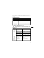
Grundfos UPS 200 Series Fitting Instructions Manual
- Categoria
- Gruppi di continuità (UPS)
- Tipo
- Fitting Instructions Manual
Questo manuale è adatto anche per

836836'6HULHV
/210RGXOH
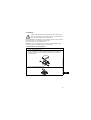
Fitting instructions
Montageanleitung
Istruzioni di montaggio
Instrucciones de montaje
Instruções de montagem
£ÄÈǽÅ×ÔÏÐÏÕ»ÔÈÓÈ×
Montage instructies
Monteringsanvisning
Asennusohje
Monteringsvejledning
TM01 8185 5199

3
836836'6HULHV
/210RGXOH
Fitting instructions Page 4
Montageanleitung Seite 11
Istruzioni di montaggio Pag. 19
Instrucciones de montaje Pág. 27
Instruções de montagem Pág. 35
£ÄÈǽÅ×ÔÏÐÏÕ»ÔÈÓÈ× Å̽ÄÁ
Montage instructies Pag. 51
Monteringsanvisning Sida 59
Asennusohje Sivu 66
Monteringsvejledning Side 73

4
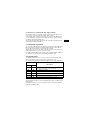
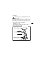
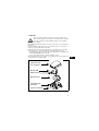
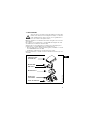
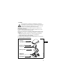
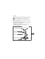
1. General
Note: Pumps with modules must not be connected to a frequency converter.
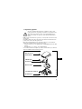
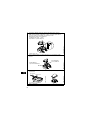
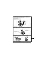
Together with the basic module, the LON module is built into the terminal box
of UPS Series 200 pumps.
In addition to the functions of the basic module (see fitting instructions for the
basic module), the LON module offers the following functions:
• Data transmission between a Local Operating Network (LON) and
GRUNDFOS UPS Series 200 pumps.
• Indicator lights for operating and fault indication.
For further information, see the documentation files on the floppy disk sup-
plied with the LON module.
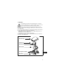
Before removing the terminal box module, these fitting instructions
should be studied carefully. The installation and operation should
also be in accordance with local regulations and accepted codes of
good practice.
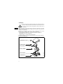
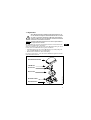
TM01 8185 5199
LON module
Basic module
Speed switch
Terminal box cover
Terminal box
Service PIN

5
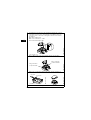
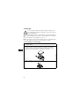
2. Fitting
Before the LON module is fitted, the basic module must be fitted and con-
nected to the terminal box, see fitting instructions for the basic module.
See fitting procedure in section 2.1.
Note: If the position of the speed switch has to be changed after the LON
module has been fitted, first remove the module.
2.1 Fitting procedure
Before removing the terminal box cover, make sure that the elec-
tricity supply has been switched off and that it cannot be acciden-
tally switched on.
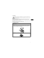
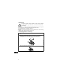
1. Switch off the electricity supply to the pump by means of the external
mains switch.
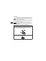
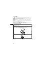
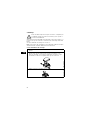
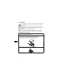
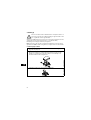
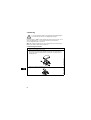
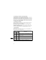
2. Remove the terminal box cover.
Fit the screwed connection supplied with the module to the terminal
box. The screwed connection can be connected on the right or left
side of the terminal box, as required.
TM01 1483 4697
3. Remove the cover from the speed switch.
TM01 1485 4697

6
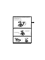
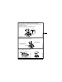
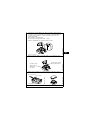
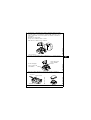
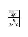
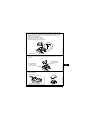
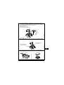
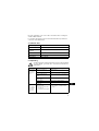
4. Lead the BUS connection into the terminal box through the screwed
connection and connect it to the terminals of the LON module. The
connection can be connected on the right or left side of the module,
as required.
BUS cable requirements:
Wire cross-section: 0,25 - 1 mm².
Unscreened twisted-pair cable.
* See section 2.2.
TM01 8186 5199
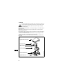
5. Fit the LON module on the basic module and the speed switch.
Make sure that the plugs engage.
TM01 8187 5199
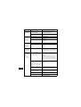
6. Remove the toothed disc and the light guide. Fit the terminal box
cover.
TM01 8189 5199
TM01 3940 4898
7. Switch on the electricity supply.
LON
*
24V
Plug connection
for speed switch
Plug connection
for basic module
Terminal box cover
Light guide
Toothed disc

7
2.2 Connection of external 24 VDC supply voltage
As the LON module is electrically connected via the basic module, it is not
necessary to connect an external 24 VDC supply voltage.
If an 24 VDC supply voltage is connected, the contact to the LON module
can be maintained even if the basic module fails and the supply voltage to
the LON module thereby disappears.
An external 24 VDC supply voltage must be electrically separated from the
mains supply by double insulation.
3. Connection to network
To connect the LON module to the network, activate the Service PIN button.
When the button is activated, the LON module transmits a unique 48 bit
ID-code (Neuron ID), which is registered by the network.
This unique code can also be found on the label situated on the side of the
LON module. The bar code is in Code 128 format.
An additional label with the same unique code is supplied with the LON mod-
ule. This label can be attached to the building installation plan.
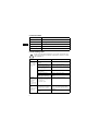
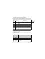
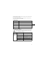
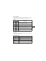
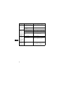
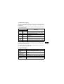
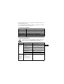
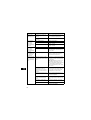
4. Indicator lights
The LON module incorporates a green, a yellow and a red indicator light
which are visible through the window in the terminal box cover.
The function of the green and red indicator lights is shown in the table below:
* The fault cause can be read out via the BUS signal.
The yellow indicator light is a service LED indicating various conditions of the
LON network.
For further information, see the documentation files on the floppy disk sup-
plied with the LON module.
Indicator lights
Description
Green Red
Off Off
The pump has been stopped. The electricity supply
has been switched off or phase missing.
On Off The pump is operating.
On On The pump is operating but is faulty.*
Off On The pump has stopped because of a fault.*
Flashing Off The pump has been set to stop.
Flashing On The pump is faulty and has been set to stop.*

8
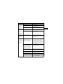
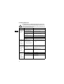
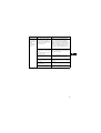
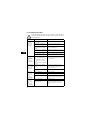
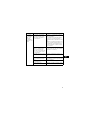
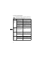
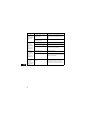
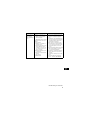
5. Technical data
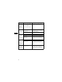
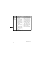
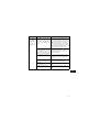
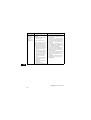
6. Fault finding chart
Transceiver type FTT - 10.
Recommended cable Unscreened twisted-pair cable.
Transmission speed 78 kBits/s.
Protocol LonTalk
.
Supply voltage External 24 VDC ±25%, see section 2.2.
Current consumption Maximum 200 mA.
Before removing the terminal box cover, make sure that the elec-
tricity supply has been switched off and that it cannot be acciden-
tally switched on.
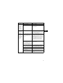
Fault Cause Remedy
The pump
does not run.
None of the in-
dicator lights
are on.
One fuse in the installation
is blown.
Replace the fuse.
External mains switch
switched off.
Switch on the mains switch.
Current-/voltage-operated
earth-leakage circuit
breaker has tripped out.
Repair insulation defects and cut in the
circuit breaker.
Missing phase (only three-
phase pumps).
Check fuses and connections.
The pump is defective. Repair or replace the pump.
The basic module or the
LON module is defective.
Repair or replace the defective
module.
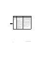
The pump
does not run.
The green indi-
cator light is
flashing.
The red indica-
tor light is off.
The pump has been stopped
in one of the following ways:
1. External on/off switch in
position off.
2. Via BUS signal.
1. Switch on the on/off switch.
2. Start the pump via BUS signal.
The pump
runs.
The green and
red indicator
lights are on.
The pump is running with
wrong direction of rotation
(only three-phase pumps).
Switch off the electricity supply by
means of the external mains switch
and interchange two phases in the ter-
minal box.
The basic module has lost
its data.
Replace the basic module.

9
Noise in the
system.
The green indi-
cator light is
on.
The red indica-
tor light is off.
Air in the system. Vent the system.
The pump flow is too high. Reduce the pump performance
(change to lower speed).
The pressure is too high. Reduce the pump performance
(change to lower speed).
Noise in the
pump.
The green indi-
cator light is
on.
The red indica-
tor light is off.
Air in the pump. Vent the pump.
The inlet pressure is too low. Increase the inlet pressure and/or
check the air volume in the expansion
tank, if installed.
Insufficient
heat in some
places in the
heating sys-
tem.
The pump performance is
too low.
Increase the pump performance
(change to higher speed), if possible,
or replace the pump with a pump with
a higher flow.
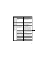
The pump
does not run.
The green indi-
cator light is
off.
The red indica-
tor light is on.
The pump has been cut out
by the thermal overload
switch due to high liquid
temperature or blocked ro-
tor.
Check that the liquid temperature falls
within the specified range. The pump
starts automatically after cooling.
Note: If the thermal overload switch
has cut out the pump five times within
one hour, the pump can only be re-
started after the electricity supply has
been switched off.
The speed switch module
and the basic module are
not of the same type. One is
a three-phase module and
the other is a single-phase
module.
Replace one of the modules so that it
is suitable for the pump type (single-
phase or three-phase).
The speed switch module
has not been fitted.
Switch off the electricity supply by
means of the external mains switch
and fit the speed switch module.
Electricity supply failure
(overvoltage/undervoltage).
Check that the electricity supply falls
within the specified range.
Missing phase (only three-
phase pumps).
Check fuses and connections.
Fault in electronics. Replace the modules in the terminal
box. Contact GRUNDFOS.
Fault Cause Remedy

10
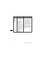
The pump
does not run.
The green indi-
cator light is
flashing.
The red indica-
tor light is on.
The pump has been stopped
in one of the following ways:
1. External on/off switch in
position off.
2. Via BUS signal.
The following faults exist/
existed (have disappeared):
a) Wrong phase sequence.
b) The pump has been cut
out by the thermal over-
load switch.
c) The speed switch module
and the basic module are
not of the same type.
One is a three-phase
module and the other is a
single-phase module.
d) The speed switch module
has not been fitted.
e) Supply failure.
f) Missing phase.
g) Fault in electronics.
a) Switch off the electricity supply by
means of the external mains switch
and interchange two phases in the
terminal box.
b) Check that the liquid temperature
falls within the specified range. The
pump starts automatically after
cooling.
c) Replace one of the modules so that
it is suitable for the pump type (sin-
gle-phase or three-phase).
d) Switch off the electricity supply by
means of the external mains switch
and fit the speed switch module.
e) Check that the electricity supply
falls within the specified range.
f) Check fuses and connections.
g) Replace the modules in the termi-
nal box. Contact GRUNDFOS.
Fault Cause Remedy
Subject to alterations.

11
1. Allgemeines
Das LON-Modul ist zusammen mit dem Basismodul in den Klemmenkasten
der UPS Serie 200 Pumpen einzubauen.
Außer den Funktionen des Basismoduls (siehe Montageanleitung des Basis-
moduls) bietet das LON-Modul die folgenden Funktionen:
• Datenübertragung zwischen einem LON-Netzwerk (Local Operating Net-
work) und GRUNDFOS UPS Serie 200 Pumpen.
• Meldeleuchten für Betriebs- bzw. Störmeldung.
Für weitere Informationen, siehe die mit dem LON-Modul gelieferte Diskette
mit Dokumentationsdateien.
Diese Montageanleitung enthält grundlegende Hinweise, die
bei der Auswechselung des Klemmenkastenmoduls zu beach-
ten sind. Sie ist daher unbedingt vor Montage und Inbetrieb-
nahme vom Monteur zu lesen. Weiterhin sind die bestehenden
nationalen Vorschriften zu beachten.
Pumpen mit Modulen dürfen nicht an einen Frequenzumrich-
ter angeschlossen werden.
TM01 8185 5199
Achtung
LON-Modul
Basismodul
Drehzahlschalter
Klemmenkastendeckel
Klemmenkasten
Service PIN

12
2. Montage
Vor der Montage des LON-Moduls muß das Basismodul im Klemmenkasten
montiert und angeschlossen sein, siehe Montageanleitung des Basismoduls.
Siehe Vorgehensweise in Abschnitt 2.1.
2.1 Vorgehensweise zur Montage des LON-Moduls
Vor dem Entfernen des Klemmenkastendeckels muß die Ver-
sorgungsspannung unbedingt allpolig abgeschaltet sein. Es
muß sichergestellt werden, daß diese nicht versehentlich wie-
der eingeschaltet werden kann.
Falls die Drehzahlschalterstellung nach der Montage des
LON-Moduls geändert werden soll, muß das Modul zuerst ent-
fernt werden.
1. Versorgungsspannung mit dem externen Netzschalter abschalten.
2. Klemmenkastendeckel entfernen.
Die mitgelieferte Verschraubung in den Klemmenkasten einschrau-
ben. Die Verschraubung läßt sich wahlweise auf der rechten oder
linken Seite des Klemmenkastens montieren.
TM01 1483 4697
3. Deckel des Drehzahlschalters entfernen.
TM01 1485 4697
Achtung

13
4. Die BUS-Verbindung durch die Verschraubung in den Klemmenka-
sten führen und an die Klemmen des LON-Moduls anschließen. Die
Verbindung läßt sich wahlweise auf der rechten oder linken Seite
des Moduls montieren.
Anforderungen an BUS-Kabel:
Leiterquerschnitt: 0,25 - 1 mm².
Nicht-abgeschirmte Doppelleitung.
* Siehe Abschnitt 2.2.
TM01 8186 5199
5. LON-Modul auf das Basismodul und den Drehzahlschalter montie-
ren. Es ist darauf zu achten, daß die beiden Stecker ineinander ein-
rasten.
TM01 8187 5199
6. Zahnscheibe und Lichtleiter entfernen. Klemmenkastendeckel mon-
tieren.
TM01 8189 5199
TM01 3940 4898
7. Versorgungsspannung einschalten.
LON
*
24V
Steckerverbindung
zum Drehzahlschalter
Steckerverbindung
zum Basismodul
Klemmenkastendeckel
Lichtleiter
Zahnscheibe

14
2.2 Anschluß von 24 VDC Versorgungsspannung
Da das LON-Modul über das Basismodul mit Spannung versorgt wird, ist es
unnötig, eine externe 24 VDC Versorgungsspannung anzuschließen.
Durch den Anschluß einer externen 24 VDC Versorgungsspannung kann die
Verbindung zum LON-Modul erhalten werden, falls das Basismodul gestört
wird und die Versorgungsspannung zum LON-Modul dadurch verschwindet.
Eine externe 24 VDC Versorgungsspannung muß mit einer Doppelisolierung
von der Netzspannung galvanisch getrennt sein.
3. Anschluß ans Netzwerk
Beim Anschluß des LON-Moduls ans Netzwerk die Taste Service PIN akti-
vieren. Wenn die Taste aktiviert wird, sendet das LON-Modul einen bestimm-
ten 48-Bit-ID-Code (Neuron ID), der vom Netzwerk registriert wird.
Dieser bestimmte Code ist auch auf dem Aufkleber an der Seite des LON-
Moduls aufgedruckt. Der Strichcode hat das Format Code 128.
Mit dem LON-Modul wird ein zusätzlicher Aufkleber mit demselben bestimm-
ten Code geliefert. Dieser Aufkleber kann z.B. auf den Gebäudeinstallations-
plan aufgeklebt werden.

15
4. Meldeleuchten
Das LON-Modul besitzt eine grüne, eine gelbe und eine rote Meldeleuchte,
die im Fenster des Klemmenkastendeckels sichtbar sind.
Die Funktion der grünen und der roten Meldeleuchte geht aus der nachste-
henden Tabelle hervor:
*Störungsursachen können über das BUS-Signal aufgerufen werden.
Die gelbe Meldeleuchte ist eine Service LED, die verschiedene Zustände
des LON-Netzwerkes anzeigt.
Für weitere Informationen, siehe die mit dem LON-Modul gelieferte Diskette
mit Dokumentationsdateien.
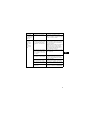
5. Technische Daten
Meldeleuchten
Beschreibung
GrünRot
Leuchtet
nicht
Leuchtet
nicht
Die Pumpe wurde ausgeschaltet. Die Versorgungs-
spannung ist abgeschaltet oder eine Phase ist aus-
gefallen.
Leuchtet
Leuchtet
nicht
Die Pumpe läuft.
Leuchtet Leuchtet Die Pumpe ist in Betrieb aber ist gestört.*
Leuchtet
nicht
Leuchtet Die Pumpe hat wegen einer Störung abgeschaltet.*
Blinkt
Leuchtet
nicht
Die Pumpe wurde ausgeschaltet.
Blinkt Leuchtet Die Pumpe ist gestört und wurde ausgeschaltet.*
Transceivertyp FTT - 10.
Empfohlenes Kabel Nicht-abgeschirmte Doppelleitung.
Übertragungs-
geschwindigkeit
78 kBits/s.
Protokoll LonTalk
.
Versorgungs-
spannung
Externe 24 VDC ±25%, siehe Abschnitt 2.2.
Stromverbrauch Max. 200 mA.

16
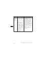
6. Störungsübersicht
Vor dem Entfernen des Klemmenkastendeckels muß die Ver-
sorgungsspannung unbedingt allpolig abgeschaltet sein. Es
muß sichergestellt werden, daß diese nicht versehentlich wie-
der eingeschaltet werden kann.
Störung
Ursache Abhilfe
Die Pumpe
läuft nicht.
Keine der Mel-
deleuchten
leuchtet.
Eine Sicherung in der Instal-
lation ist durchgebrannt.
Sicherung auswechseln.
Der externe Netzschalter ist
ausgeschaltet.
Netzschalter einschalten.
Der Fehlerstrom- oder Feh-
lerspannungsschutzschalter
hat ausgelöst.
Isolationsfehler beseitigen und Schutz-
schalter wieder einschalten.
Fehlende Phase (nur bei
Drehstrompumpen).
Sicherungen und Anschluß prüfen.
Die Pumpe ist defekt. Pumpe reparieren oder auswechseln.
Basismodul oder LON-Mo-
dul defekt.
Modul reparieren oder auswechseln.
Die Pumpe
läuft nicht.
Die grüne Mel-
deleuchte
blinkt.
Die rote Mel-
deleuchte
leuchtet nicht.
Die Pumpe wurde ausge-
schaltet.
Mögliche Ursachen:
1. Externer EIN-/AUS-
Schalter ausgeschaltet.
2. Über das BUS-Signal.
1. Externen EIN-/AUS-Schalter ein-
schalten.
2. Pumpe über das BUS-Signal ein-
schalten.
Die Pumpe
läuft.
Die grüne Mel-
deleuchte
leuchtet.
Die rote Mel-
deleuchte
leuchtet.
Die Pumpe läuft mit falscher
Drehrichtung (nur bei Dreh-
strompumpen).
Versorgungsspannung mit dem exter-
nen Netzschalter abschalten und zwei
Phasen im Klemmenkasten der Pumpe
vertauschen.
Das Basismodul hat seine
Daten verloren.
Basismodul auswechseln.
Die Anlage
macht Geräu-
sche.
Die grüne Mel-
deleuchte
leuchtet.
Die rote Mel-
deleuchte
leuchtet nicht.
Luft in der Anlage. Anlage entlüften.
Förderstrom zu groß. Pumpenleistung senken (niedrigere
Drehzahl wählen).
Förderdruck zu hoch. Pumpenleistung senken (niedrigere
Drehzahl wählen).

17
Die Pumpe
macht Geräu-
sche.
Die grüne Mel-
deleuchte
leuchtet.
Die rote Mel-
deleuchte
leuchtet nicht.
Luft in der Pumpe. Pumpe entlüften.
Zulaufdruck zu niedrig. Zulaufdruck erhöhen und/oder Gasvo-
lumen im Ausdehnungsgefäß (falls vor-
handen) prüfen.
Ungenügende
Wärme in der
Heizungsan-
lage.
Pumpenleistung zu gering. Pumpenleistung erhöhen (höhere
Drehzahl wählen), falls möglich, oder
die Pumpe durch eine Pumpe mit hö-
herer Leistung ersetzen.
Die Pumpe
läuft nicht.
Die grüne Mel-
deleuchte
leuchtet nicht.
Die rote Mel-
deleuchte
leuchtet.
Der Thermoschalter hat die
Pumpe ausgeschaltet, weil
die Medientemperatur zu
hoch oder der Rotor blok-
kiert ist.
Prüfen, ob die Medientemperatur im
spezifizierten Bereich liegt.
Die Pumpe schaltet nach ausreichen-
der Abkühlung automatisch wieder ein.
Achtung: Hat der Thermoschalter die
Pumpe fünfmal binnen einer Stunde
ausgeschaltet, kann die Pumpe erst
nach Abschalten der Versorgungs-
spannung wieder eingeschaltet wer-
den.
Das Drehzahlschaltermodul
und das Basismodul sind
nicht vom gleichen Typ.
Ein Modul ist dreiphasig und
das andere ist einphasig.
Ein Modul auswechseln (einphasig
oder dreiphasig).
Das Drehzahlschaltermodul
ist nicht montiert.
Versorgungsspannung mit dem exter-
nen Netzschalter abschalten und das
Drehzahlschaltermodul montieren.
Netzstörung (Über-/Unter-
spannung).
Prüfen, ob die Versorgungsspannung
im spezifizierten Bereich liegt.
Phasenausfall (nur Dreh-
strompumpen).
Sicherungen und Anschlüsse prüfen.
Störung in der Elektronik. Module im Klemmenkasten auswech-
seln. Mit GRUNDFOS Verbindung auf-
nehmen.
Störung
Ursache Abhilfe

18
Die Pumpe
läuft nicht.
Die grüne Mel-
deleuchte
blinkt.
Die rote Mel-
deleuchte
leuchtet.
Die Pumpe wurde ausge-
schaltet.
Mögliche Ursachen:
1. Externer EIN-/AUS-
Schalter ausgeschaltet.
2. Über das BUS-Signal.
Die folgenden Störungen
anliegen oder haben ange-
legen:
a) Falsche Phasenfolge.
b) Die Pumpe wurde vom
Thermoschalter ausge-
schaltet.
c) Das Drehzahlschaltermo-
dul und das Basismodul
sind nicht vom gleichen
Typ. Ein Modul ist drei-
phasig und das andere
ist einphasig.
d) Das Drehzahlschaltermo-
dul ist nicht montiert.
e) Netzstörung.
f) Phasenausfall.
g) Störung in der Elektronik.
a) Versorgungsspannung mit dem ex-
ternen Netzschalter abschalten und
zwei Phasen im Klemmenkasten
der Pumpe vertauschen.
b) Prüfen, ob die Medientemperatur im
spezifizierten Bereich liegt. Die
Pumpe schaltet nach ausreichen-
der Abkühlung automatisch wieder
ein.
c) Ein Modul auswechseln (einphasig
oder dreiphasig).
d) Versorgungsspannung mit dem ex-
ternen Netzschalter abschalten und
das Drehzahlschaltermodul montie-
ren.
e) Prüfen, ob die Versorgungsspan-
nung im spezifizierten Bereich liegt.
f) Sicherungen und Anschlüsse prü-
fen.
g) Module im Klemmenkasten aus-
wechseln. Mit GRUNDFOS Verbin-
dung aufnehmen.
Störung
Ursache Abhilfe
Technische Änderungen vorbehalten.

19
1. Generalità
Nota: Le pompe dotate di moduli non devono essere collegate ad un conver-
titore di frequenza.
Il modulo LON deve essere installato assieme al modulo base nella scatola
di controllo delle pompe UPS Serie 200.
Oltre alle funzioni del modulo base (vedere le istruzioni di montaggio del mo-
dulo base), il modulo LON offre le seguenti funzioni:
• Trasmissione dati tra la rete di funzionamento locale (LON) e le pompe
GRUNDFOS UPS serie 200.
• LED di segnalazione per indicazioni di funzionamento e di guasto.
Per ulteriori informazioni, riferirsi alla documentazione contenuta nel disco
floppy fornito unitamente al modulo LON.
Prima di rimuovere il modulo, studiate attentamente queste istru-
zioni. Le operazioni di installazione devono essere effettuate in ac-
cordo alle leggi vigenti localmente e alle comuni regole di pratica
della regola d’arte.
TM01 8185 5199
Modulo LON
Modulo base
Selettore di velocità
Scatola di controllo
Service PIN
Coperchio della
scatola di controllo

20
2. Montaggio
Prima di installare il modulo LON, il modulo base deve essere installato e
collegato alla scatola di controllo secondo le corrispondenti istruzioni di mon-
taggio.
Vedere la procedura di montaggio nel cap. 2.1.
Nota: Se occorre modificare la posizione del selettore di velocità dopo l’in-
stallazione del modulo LON, rimuovere prima il modulo.
2.1 Procedura di montaggio
Prima di rimuovere il coperchio della scatola di controllo, accer-
tarsi che l’alimentazione elettrica sia stata tolta e che non possa
essere riattivata accidentalmente.
1. Staccare l’alimentazione elettrica alla pompa per mezzo dell’interrut-
tore di rete esterno.
2. Rimuovere il coperchio della scatola di controllo.
Inserire il raccordo filettato in dotazione col modulo nella scatola di
controllo. Il raccordo filettato può essere inserito sul lato destro o si-
nistro della scatola di controllo, secondo necessità.
TM01 1483 4697
3. Rimuovere il coperchio del selettore di velocità.
TM01 1485 4697

21
4. Inserire il collegamento BUS nella scatola di controllo attraverso il
raccordo filettato e collegarlo ai morsetti del modulo LON.
Il collegamento può avvenire sul lato destro o sinistro del modulo,
secondo necessità.
Requisiti del cavo BUS:
Sezione trasversale del conduttore: 0,25 - 1 mm².
Cavo non schermato a due conduttori interni.
* Vedere cap. 2.2.
TM01 8186 5199
5. Inserire il modulo LON sul selettore di velocità del modulo base. Ve-
rificare il corretto incastro dei contatti.
TM01 8187 5199
6. Rimuovere la rondella di fissaggio e le barrette ottiche. Installare il
coperchio della scatola di controllo.
TM01 8189 5199
TM01 3940 4898
7. Riattivare l’alimentazione elettrica.
LON
*
24V
Contatti elettrici del
selettore velocità
Contatti elettrici
del modulo base
Coperchio della scatola di controllo
Barrette ottiche
fissaggio
Rondella di
La pagina si sta caricando...
La pagina si sta caricando...
La pagina si sta caricando...
La pagina si sta caricando...
La pagina si sta caricando...
La pagina si sta caricando...
La pagina si sta caricando...
La pagina si sta caricando...
La pagina si sta caricando...
La pagina si sta caricando...
La pagina si sta caricando...
La pagina si sta caricando...
La pagina si sta caricando...
La pagina si sta caricando...
La pagina si sta caricando...
La pagina si sta caricando...
La pagina si sta caricando...
La pagina si sta caricando...
La pagina si sta caricando...
La pagina si sta caricando...
La pagina si sta caricando...
La pagina si sta caricando...
La pagina si sta caricando...
La pagina si sta caricando...
La pagina si sta caricando...
La pagina si sta caricando...
La pagina si sta caricando...
La pagina si sta caricando...
La pagina si sta caricando...
La pagina si sta caricando...
La pagina si sta caricando...
La pagina si sta caricando...
La pagina si sta caricando...
La pagina si sta caricando...
La pagina si sta caricando...
La pagina si sta caricando...
La pagina si sta caricando...
La pagina si sta caricando...
La pagina si sta caricando...
La pagina si sta caricando...
La pagina si sta caricando...
La pagina si sta caricando...
La pagina si sta caricando...
La pagina si sta caricando...
La pagina si sta caricando...
La pagina si sta caricando...
La pagina si sta caricando...
La pagina si sta caricando...
La pagina si sta caricando...
La pagina si sta caricando...
La pagina si sta caricando...
La pagina si sta caricando...
La pagina si sta caricando...
La pagina si sta caricando...
La pagina si sta caricando...
La pagina si sta caricando...
La pagina si sta caricando...
La pagina si sta caricando...
La pagina si sta caricando...
-
 1
1
-
 2
2
-
 3
3
-
 4
4
-
 5
5
-
 6
6
-
 7
7
-
 8
8
-
 9
9
-
 10
10
-
 11
11
-
 12
12
-
 13
13
-
 14
14
-
 15
15
-
 16
16
-
 17
17
-
 18
18
-
 19
19
-
 20
20
-
 21
21
-
 22
22
-
 23
23
-
 24
24
-
 25
25
-
 26
26
-
 27
27
-
 28
28
-
 29
29
-
 30
30
-
 31
31
-
 32
32
-
 33
33
-
 34
34
-
 35
35
-
 36
36
-
 37
37
-
 38
38
-
 39
39
-
 40
40
-
 41
41
-
 42
42
-
 43
43
-
 44
44
-
 45
45
-
 46
46
-
 47
47
-
 48
48
-
 49
49
-
 50
50
-
 51
51
-
 52
52
-
 53
53
-
 54
54
-
 55
55
-
 56
56
-
 57
57
-
 58
58
-
 59
59
-
 60
60
-
 61
61
-
 62
62
-
 63
63
-
 64
64
-
 65
65
-
 66
66
-
 67
67
-
 68
68
-
 69
69
-
 70
70
-
 71
71
-
 72
72
-
 73
73
-
 74
74
-
 75
75
-
 76
76
-
 77
77
-
 78
78
-
 79
79


Grundfos UPS 200 Series Fitting Instructions Manual
- Categoria
- Gruppi di continuità (UPS)
- Tipo
- Fitting Instructions Manual
- Questo manuale è adatto anche per
in altre lingue
- English: Grundfos UPS 200 Series
- español: Grundfos UPS 200 Series
- Deutsch: Grundfos UPS 200 Series
- Nederlands: Grundfos UPS 200 Series
- português: Grundfos UPS 200 Series
- dansk: Grundfos UPS 200 Series
- svenska: Grundfos UPS 200 Series
- suomi: Grundfos UPS 200 Series
Documenti correlati
-
Grundfos UPE Series 2000 Installation And Operating Instructions Manual
-
-
Grundfos MAGNA 25-100 N Installation And Operating Instructions Manual
-
-
-
-
-
-
Grundfos DME 375 Installation And Operating Instructions Manual
-